Herunterladen Inhalt Inhalt Diese Seite drucken
bürkert 8020 Bedienungsanleitung

bürkert 8020 Bedienungsanleitung

Schaufelrad durchfluss-sensor
Vorschau ausblenden Andere Handbücher für 8020:
Inhaltsverzeichnis

Werbung

Verfügbare Sprachen

Verfügbare Sprachen

8020
SCHAUFELRAD DURCHFLUSS-SENSOR
Bedienungsanleitung
© Bürkert 2006
Technische Änderung vorbehalten

Werbung

Inhaltsverzeichnis
loading

Inhaltszusammenfassung für bürkert 8020

  • Seite 1 8020 SCHAUFELRAD DURCHFLUSS-SENSOR Bedienungsanleitung © Bürkert 2006 Technische Änderung vorbehalten...
  • Seite 2: Inhaltsverzeichnis

    Elektrische Daten ....................11 Werkstoffe ........................12 Umgebung .......................13 Abmessungen ......................13 Normenbezüge ......................13 4. WARTUNG............................14 Pflege und Reinigung ....................14 Bestell-Nummern der Ersatzteile ................14 Bestell-Nummern der kompletten Sensoren ............14 5. ANHANG ............................15 Beschreibung des Typenschilds .................15 Auswahl Fitting / Rohrnennweite ................15 8020...
  • Seite 3: Einleitung

    Schützen Sie das Gerät von elektromagnetischen Störungen, von Ultraviolett- bestrahlung und, bei einer Außenanwendung, von den Wetterbedingungen. Wenn diese Anweisungen nicht befolgt werden und das Gerät nicht entsprechend den Angaben verwendet wird, wird keinerlei Haftung übernommen und die Garantie für das Gerät erlischt. 8020...
  • Seite 4: Aufbau Und Messprinzip

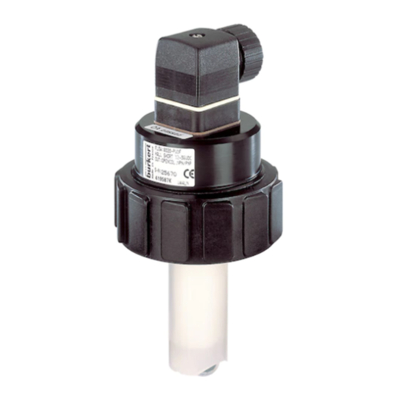
    EINLEITUNG 1.3 AUFBAU UND MESSPRINZIP Der Sensor 8020 ist zur Durchfluss-Messung von neutralen oder leicht aggressiven aber partikelfreien Flüssigkeiten bestimmt. Der Sensor besteht aus einem Messwertaufnehmer und einem mit Flügelrad versehenen Messfinger. Vier Magnete sind in das Flügelrad eingesetzt. In Bewegung gesetzt durch die strömende Flüssigkeit erzeugt das Flügelrad im Mess- wertaufnehmer eine Messfrequenz f, die dem Durchfluss Q proportional ist.
  • Seite 5: Installation

    PVDF / Metall (PN 10) PVC (PN 10) PP (PN 10) T˚ [˚C] +110 Vorsichtsmaßnahme bei der Demontage: Dem verwendeten Prozess entsprechend müssen geeignete Vorsichts- maßnahmen getroffen werden, bevor der Sensor abmontiert wird (ag- gressive Flüssigkeiten, hohe Flüssigkeits-Druck und -Temperatur...). 8020...
  • Seite 6: Einbau Des Sensors In Das Fitting

    INSTALLATION 2.2 EINBAU DES SENSORS IN DAS FITTING Der Durchflussmesser 8020 kann mit speziell entwickelten Bürkert-Fittings S020 in Rohrleitungen montiert werden. Der Durchflusssensor kann beliebig in horizontalen oder vertikalen Rohrleitungen einge- baut werden. Beim Einbau des Sensors 5 beachten Sie die in Abschnitt 2.1 und in der Bedienungsanleitung des Fittings angegebenen Montageanweisungen.
  • Seite 7: Hinweise Zum Elektrischen Anschluss

    Schraube [1] festschrauben, um die Dichtheit und einen korrekten elektrischen Anschluss zu vergewissern. 2.3.2 Verkabelung der mit 2 Pulsausgängen versehenen Hall-Effekt-Version Diese Ausführung weist einen NPN-Transistor-Ausgang und einen PNP-Transistor- Ausgang auf. PNP-Transistor-Ausgang V+ (12-36 VDC) NPN-Transistor- Ausgang Die max. Anschlussentfernung ist 50 Meter. 8020...
  • Seite 8: Hall-Effekt-Version

    Diese Ausführung weist einen NPN-Transistor-Ausgang auf. Nicht belegt V+ (12-36 VDC) NPN-Transistor- Ausgang Die max. Anschlussentfernung ist 50 Meter. Elektrischer Anschluss des NPN-Pulsausgangs an eine SPS Der NPN-Pulsausgang der Low Power Hall-Effekt-Version wird gleichermaßen wie den NPN-Ausgang der Hall-Effekt-Version verkabelt (siehe § 2.3.2). 8020...
  • Seite 9: Verkabelung Des Sinus-Ausgangs Einer Spulen-Version

    2.3.4 Verkabelung des Sinus-Ausgangs einer Spulen-Version Diese Ausführung weist einen Sinus-Ausgang auf. Nicht belegt Nicht belegt Sinusausgang Sinusausgang Die max. Anschlussentfernung ist 10 Meter. Elektrischer Anschluss des Sinus-Ausgangs an eine SPS Sensor Empfänger Last Spule Elektrischer Anschluss des Sinus-Ausgangs an eine SPS 8020...
  • Seite 10: Anschlussbeispiele

    Für weitere elektrische Anschlüsse und korrekte Einstellung der verschiedenen Schalter ziehen Sie sich bitte auf die Bedienungsanleitung des 8025 Batch Anschluss zwischen 8020, Low Power Hall- Effekt-Version, und Dosiergerät 8025 Batch (1) Ist keine direkte Erdung möglich, schließen Sie einen 100 nF / 50 V-Kondensator zwischen dem negativen Anschluss der Versorgungsquelle und der Erde an.
  • Seite 11: Technische Daten

    300 Hz, Spitze-Spitze-Spannung von ungefähr 2,8 mV / Hz unter einer 50 kΩ-Βürde (Frequenz = K-Faktor x Durchfluss; der Wert des K-Faktors muss von der Bedienungsanleitung des Fittings entnommen werden) Kabellänge max. 10 m, abgeschirmt Kabelquerschnitt max. 1.5 mm 8020...
  • Seite 12: Werkstoffe

    Kurzschlusschutz vorhanden Kabellänge max. 50 m, abgeschirmt Kabelquerschnitt max. 1.5 mm 3.3 WERKSTOFFE Gehäuse PE-HD Überwurfmutter Stecker und Steckverbinder EN175301-803 PA (Kontakte aus galvanisch versilbertem Messing) Finger-Armatur, Flügelrad PVDF Axe und Lager Keramik Dichtung FKM, standard (EPDM auf Anfrage) 8020...
  • Seite 13: Umgebung

    (Betrieb und Lager) -15 °C bis +60 °C Relative Luftfeuchtigkeit < 80%, nicht kondensierend Schutzklasse des Gehäuses IP65, mit eingestecktem und festgeschraubtem Gerätestecker 3.5 ABMESSUNGEN 8020 mit Fitting S020 75 mm Nennweite H [mm] 8020, kurze und lange [mm] T-Fitting...
  • Seite 14: Wartung

    Low Power Hall-Effekt, kurze EN175301-803-Stecker 419591 Ausführung über Transmitter Low Power Hall-Effekt, lange EN175301-803-Stecker 419593 Ausführung ohne Spule, kurze Ausführung EN175301-803-Stecker 419583 ohne Spule, lange Ausführung EN175301-803-Stecker 419585 Adresse des Herstellers Bürkert & Cie Rue du Giessen 67220 TRIEMBACH-au-VAL FRANCE 8020...
  • Seite 15: Anhang

    ANHANG 5.1 BESCHREIBUNG DES TYPENSCHILDS Sensortyp Dichtungswerkstoff Fingerwerkstoff FLOW:8020-FKM-PVDF Sensordaten und eventuell, HALL LONG 12-36VDC OUT:OPENCOL.NPN/PNP Betriebsspannung Ausgangsdaten S-N:21219 CE-Logo 419589 W48LG Hersteller-Nummer Serien-Nummer Bestell-Nummer 5.2 AUSWAHL FITTING / ROHRNENNWEITE 5000 DN 400 l/min DN 350 50000 DN 300 2000...
  • Seite 16 10000 10'' DN250 8'' DN200 5000 6'' DN150 2000 5'' DN125 4'' DN100 1000 3'' DN80 2 1/2'' DN65 2'' DN50 1 1/2'' DN40 1 1/4'' DN32 1'' DN25 3/4'' DN20 1/2'' DN15 0.05 0.02 0.01 0.3 0.5 Flüssigkeitsgeschwindigkeit 8020...
  • Seite 17 8020 PADDLE-WHEEL FLOW SENSOR Instruction Manual © Bürkert 2006 Subject to technical change without notice...
  • Seite 18 4. MAINTENANCE ..........................14 Maintenance and cleaning ...................14 Order codes for spare parts ................14 Order codes for complete sensors ..............14 5. ANNEX ..............................15 Label description ....................15 DN of the pipe - flow rate - fluid velocity diagrams ........15 8020...
  • Seite 19: Introduction

    If these instructions are ignored or the device is not used according to the specifications, no liability will be accepted and the guarantee on the device and accessories will become invalid. 8020...
  • Seite 20: Design And Measuring Principle

    INTRODUCTION 1.3 DESIGN AND MEASURING PRINCIPLE The 8020 sensor is designed for measuring the flow of neutral or slightly aggressive solid free liquids. The sensor is made up of a transducer and a measuring finger with a paddle-wheel which paddles contain magnets.
  • Seite 21: Installation

    PVDF / Metal (PN 10) PVC (PN 10) PP (PN 10) T˚ [˚C] +110 Dismounting precaution: When dismounting the sensor from the pipe, take all the necessary pre- cautions linked to the process (aggressive fluids, high fluid pressure or temperature,...). 8020...
  • Seite 22: Inserting The Sensor Into The Fitting

    INSTALLATION 2.2 INSERTING THE SENSOR INTO THE FITTING The 8020 flowmeter can be installed in any pipe using our specially designed S020 fitting system. The sensor can be installed whatever the inclination of the pipe. When mounting fitting 5, make sure to respect the instructions described in § 2.1 and within the instruction manual of the fitting.
  • Seite 23: Recommendations For Electric Connection

    Fasten screw [1] to ensure tightness and correct electrical contact. 2.3.2 Wiring the Hall version with 2 pulse outputs This version has one NPN transistor output and one PNP transistor output. PNP transistor output V+ (12-36 VDC) NPN transistor output Max. wiring distance is 50 metres. 8020...
  • Seite 24: Wiring The Low Power Hall Version With 1 Pulse Output

    Max. wiring distance is 50 metres. Connecting the NPN output to a PLC The NPN pulse output of the Low Power Hall version can be connected to a PLC in the same way as the NPN output of a Hall version (see § 2.3.2). 8020...
  • Seite 25: Wiring The Sinus Output Of A Coil Version

    2.3.4 Wiring the sinus output of a coil version This version has one sinus output. Not connected Not connected Sinus output Sinus output Max. wiring distance is 10 metres. Connecting the sinus output to a PLC Sensor Receiver Load Coil Connecting the sinus output to a PLC 8020...
  • Seite 26: Connection Examples

    Refer to the instruction manual of transmitter 8025 Batch for further electrical connections and correct positionning of switches. 8020, Low Power Hall version, connected to a batch controller 8025 Batch (1) If direct earthing is not possible, insert a 100 / 50 nF condensator between the negative terminal of the voltage supply and the earth.
  • Seite 27: Technical Data

    300 Hz, approx. 2,8 mV peak-to-peak/Hz under a 50 kΩ-load (frequency = K factor x flow rate; the K factor value must be taken from the instruc- tion manual of the fitting) Cable length max. 10 m, shielded Cable cross section, max. 1.5 mm 8020...
  • Seite 28: Materials

    50 m, shielded Cable cross section max. 1.5 mm 3.3 MATERIALS Electronic housing PE-HD EN175301-803 fixed connector and cable plug PA (contacts in brass, electro-silver plated) Finger holder, paddle-wheel PVDF Axis and bearings ceramics Gasket FKM, standard (EPDM on request) 8020...
  • Seite 29: Environment

    < 80%, non condensated Protection rating of housing IP65, the connector being plugged-in and tightened 3.5 DIMENSIONS 8020 with fitting S020 75 mm H [mm] 8020, short and long finger [mm] T fitting Saddle Plastic spigot Stainless steel spigot 156.0 153.5...
  • Seite 30: Maintenance

    419591 via transmitter Low Power Hall, long finger EN175301-803 cable plug 419593 None Coil, short finger EN175301-803 cable plug 419583 None Coil, long finger EN175301-803 cable plug 419585 Manufacturer's address Bürkert & Cie Rue du Giessen 67220 TRIEMBACH-au-VAL FRANCE 8020...
  • Seite 31: Annex

    ANNEX 5.1 LABEL DESCRIPTION Type of sensor Gasket material Finger material FLOW:8020-FKM-PVDF Sensor data and, possibly HALL LONG 12-36VDC OUT:OPENCOL.NPN/PNP supply voltage Output data S-N:21219 CE logo 419589 W48LG Manufacturer code Serial number Order code 5.2 DN OF THE PIPE - FLOW RATE - FLUID VELOCITY DIAGRAMS...
  • Seite 32 10'' DN250 8'' DN200 5000 6'' DN150 2000 5'' DN125 4'' DN100 1000 3'' DN80 2 1/2'' DN65 2'' DN50 1 1/2'' DN40 1 1/4'' DN32 1'' DN25 3/4'' DN20 1/2'' DN15 0.05 0.02 0.01 0.3 0.5 Fluid velocity 8020...
  • Seite 33 8020 CAPTEUR DE DÉBIT À AILETTE Manuel utilisateur © Bürkert 2006 Sous réserve de modifications techniques...
  • Seite 34 Entretien et nettoyage ...................14 Références de commande des pièces de rechange ........14 Références de commande des capteurs complets ........14 5. ANNEXE ............................. 15 Description de l'étiquette ..................15 Abaques débit - vitesse du fluide - DN de la conduite .........15 8020...
  • Seite 35: Introduction

    EN 100 015-1. Protéger l’appareil contre les perturbations électromagnétiques, les rayons ultraviolets et, lorsqu’il est installé à l’extérieur, des effets des conditions climatiques. Nous déclinons toute responsabilité en cas de non respect de ces instructions et dénonçons toute clause de garantie. 8020...
  • Seite 36: Construction Et Principe De Mesure

    INTRODUCTION 1.3 CONSTRUCTION ET PRINCIPE DE MESURE Le capteur 8020 est destiné à la mesure du débit dans des liquides neutres ou légère- ment agressifs et exempts de particules solides. Le capteur est pourvu d'un transducteur et d'un doigt de mesure avec une ailette dont les pales renferment un aimant.
  • Seite 37: Installation

    PP (PN 10) T˚ [˚C] +110 Précaution de démontage : Lors du démontage du capteur de la conduite, il faut s’assurer que toutes les précautions dépendant de l’application ont été prises (fluides agres- sifs, température ou pression du fluide élevée...). 8020...
  • Seite 38: Installation Du Capteur Dans Le Raccord

    INSTALLATION 2.2 INSTALLATION DU CAPTEUR DANS LE RACCORD Le débitmètre 8020 s’installe sur les conduites à l’aide de nos systèmes de raccordement spéciaux S020. Le capteur de débit peut être installé quelle que soit l'inclinaison des conduites. Lors du montage du raccord 5, respecter les consignes décrites au § 2.1 et dans le manuel utilisateur du raccord.
  • Seite 39: Consignes De Raccordement Électrique

    2.3.2 Câblage de la version Hall avec 2 sorties impulsion Cette version comporte une sortie transistor NPN et une sortie transistor PNP. Sortie transistor PNP V+ (12-36 VDC) Sortie transistor NPN La distance max. de raccordement est de 50 mètres. 8020...
  • Seite 40: Câblage De La Version Hall Low Power Avec 1 Sortie Impulsion

    Raccordement de la sortie impulsion NPN à un automate La sortie impulsion NPN de la version à effet Hall Low Power se connecte à un automate de la même manière que la sortie NPN de la version à effet Hall (voir § 2.3.2). 8020...
  • Seite 41: Câblage De La Sortie Sinusoïdale D'une Version À Bobine

    Cette version comporte une sortie sinusoïdale. Non connectée Non connectée Sortie sinusoïdale Sortie sinusoïdale La distance max. de raccordement est de 10 mètres. Raccordement de la sortie sinusoïdale à un automate Capteur Récepteur Charge Bobine Raccordement de la sortie sinusoïdale à un automate 8020...
  • Seite 42: Exemples De Raccordement

    Se référer au manuel du 8025 Batch pour toute autre connexion électrique et le positionnement adéquat des interrupteurs 8020 à effet Hall Low Power avec un contrôleur de dosage 8025 Batch (1) Si une mise à la terre directe est impossible, brancher un condensateur de 100 nF / 50 V entre la borne négative de l’ali men ta tion et la terre.
  • Seite 43: Caractéristiques Techniques

    300 Hz, env. 2,8 mV crête-à-crête/Hz sous une charge de 50 kΩ (fréquence = facteur K x débit ; la valeur du facteur K se trouve dans le manuel utilisateur du raccord) Longueur de câble max. 10 m, blindé Section du câble max. 1.5 mm 8020...
  • Seite 44: Matériaux

    Section du câble max. 1.5 mm 3.3 MATÉRIAUX Boîtier électronique PE-HD Ecrou Embase et connecteur EN175301-803 PA (contacts en laiton à argenture galvanique) Armature du doigt, ailette PVDF Axe et paliers céramique Joint FKM en standard (EPDM en option) 8020...
  • Seite 45: Environnement

    < 80%, non condensée Classe de protection du boîtier IP65, connecteur enfiché et serré 3.5 DIMENSIONS 8020 avec raccord S020 75 mm H [mm] 8020, doigt court et doigt long [mm] Raccord en T Colliers Manchon en Manchon en plastique acier inoxydable 156.0...
  • Seite 46: Maintenance

    Connecteur EN175301-803 419591 via transmetteur Hall Low Power, doigt long Connecteur EN175301-803 419593 sans Bobine, doigt court Connecteur EN175301-803 419583 sans Bobine, doigt long Connecteur EN175301-803 419585 Adresse du fabricant Bürkert & Cie Rue du Giessen 67220 TRIEMBACH-au-VAL FRANCE 8020...
  • Seite 47: Annexe

    ANNEXE 5.1 DESCRIPTION DE L'ÉTIQUETTE Type de capteur Matériau du joint Matériau du doigt FLOW:8020-FKM-PVDF Caractéristiques du capteur et, le cas HALL LONG 12-36VDC OUT:OPENCOL.NPN/PNP échéant, alimentation élec tri que Caractéristiques de la sortie S-N:21219 Logo CE 419589 W48LG Code fabricant Numéro de série...
  • Seite 48 10'' DN250 8'' DN200 5000 6'' DN150 2000 5'' DN125 4'' DN100 1000 3'' DN80 2 1/2'' DN65 2'' DN50 1 1/2'' DN40 1 1/4'' DN32 1'' DN25 3/4'' DN20 1/2'' DN15 0.05 0.02 0.01 0.3 0.5 Vitesse du fluide 8020...

Inhaltsverzeichnis