All manuals and user guides at all-guides.com Flow sensor 8030 Table of contents 1 SAFETY RECOMMENDATIONS......................4 1.1 Utilisation....................................4 1.2 Precautions at installation and commissioning..................5 1.3 Conformity to standards ...............................5 2 DESCRIPTION ..............................6 2.1 Design and measuring principle..........................6 2.2 Available versions................................7 3 TECHNICAL SPECIFICATIONS.......................8...
Seite 4
5.2 Description of the label of the sensor SE30 ................... 22 5.3 Possible combinations with the sinus version..................23 5.4 Possible combinations with the pulse version (Hall effect sensor)........24 5.5 Possible combinations with the pulse version (Low Power Hall effect sensor) ..25 5.6 Connection examples ..............................26 8030...
Always respect the safety instructions marked by the symbol opposite as well as those included in the manual. 1.1 Utilisation The 8030 sensor is designed for measuring the flow of neutral or slightly aggressive solid free liquids. There will be no manufacturer warranty for damages caused by unexpected handling or wrong usage of the device.The warranty on the...
- To clean the device, only use chemically compatible products. - Protect the sensor from electromagnetic perturbations, the rain and ultraviolet radiations. When dismounting the sensor from the pipe, take all the necessary precautions linked to the process. 1.3 Conformity to standards EMC: EN 50081-1, 61000-6-2 8030...
Flow sensor 8030 DESCRIPTION 2.1 Design and measuring principle The 8030 flow sensor is made up of an SE30 electronic module and an SE30 S030 fitting with integrated paddle-wheel. The sensor detects the rotation of the paddle-wheel which generates a...
All manuals and user guides at all-guides.com Flow sensor 8030 TECHNICAL SPECIFICATIONS General features Pipe diameter DN6 to DN65 (1/4’’ to 2’’1/2); determine the appropriate diameter using the flow-velocity- DN diagrams (see Annex) Fluid temperature, max. 100 °C, stainless steel, brass, PVDF 80 °C, PP...
Seite 11
300 Hz, approx. 2,8 mV peak-to-peak/Hz when loaded with 50 kΩ (frequency = K factor x flow rate; for the K factor value, refer to the instruction manual of the fitting) Cable length max. 10 m, shielded 8030...
Seite 12
All manuals and user guides at all-guides.com Flow sensor 8030 TECHNICAL SPECIFICATIONS Electrical features (continued) Hall effect pulse version Power supply 12-36 VDC Current consumption max. 30 mA (without load) Protection against polarity reversal Protection against voltage peaks Output data NPN and PNP transistors, open collector, 100 mA max., NPN output: 0,2-36 VDC and...
Seite 13
(316L/DIN1.4404), brass, PVC, PP, PVDF - paddle-wheel PVDF (PP on request) - axis and bearings ceramics Environment Ambient and storage temperatures -15 °C to +60 °C Relative humidity < 80%, non condensated Protection rating of housing IP65, the connector being plugged-in and tightened 8030...
Seite 15
All manuals and user guides at all-guides.com Flow sensor 8030 TECHNICAL SPECIFICATIONS Dimensions (mm) EN 175301-803 DN S030 H (mm) 95.5 95.5 100.5 105.5...
Seite 16
All manuals and user guides at all-guides.com 8030...
All manuals and user guides at all-guides.com Flow sensor 8030 INSTALLATION 4.1 General recommendations Always check the chemical compatibility of the materials the sensor is made of with the products it may be in contact with. For more information, please contact your Bürkert sales office.
- If a combined installation cannot be avoided, a minimum space of 30 cm should be respected. - Use a high quality voltage supply (filtered and stable). Install an appropriate fuse for the power supply. 8030...
- Tighten the cable gland [5]. - Place gasket [4] between the connector and the fixed connector of the 8030. - Connect the connector to the 8030. - Tighten screw [1]. 4.3.2 Wiring of the frequency output: sinus version (coil output)
All manuals and user guides at all-guides.com Flow sensor 8030 INSTALLATION 4.3.4 Wiring of the frequency output (NPN transistor output): pulse version (Low Power Hall effect sensor ) Sensor Receiver NPN transistor output Output Load Not connected NPN transistor output connection of...
Seite 23
All manuals and user guides at all-guides.com 8030...
All manuals and user guides at all-guides.com Flow sensor 8030 ANNEX 5.2 Description of the label of the sensor SE30 FLOW:SE30/8030 HALL LP OPEN COLLECTOR NEW VERSION S-N:59037 00423914 W45LG Type of sensor Sensor data and, possibly, power supply Output data «NEW VERSION»...
All manuals and user guides at all-guides.com 5.3 Possible combinations with the sinus version Type 8034 Battery-powered Wall-mounted Type 8025 Totalisator Battery-powered Wall-mounted Type 8023 4-20 mA output module 8030 - Flow sensor Sinus output 8030...
All manuals and user guides at all-guides.com Flow sensor 8030 ANNEX 5.4 Possible combinations with the pulse version (Hall effect sensor) Type 8025 Universal Type 8025 Batch (Low Flow) Wall-mounted or panel Wall-mounted or panel Type 8032 Wall-mounted Type 8021...
Wall-mounted or panel Type 8032 Wall-mounted Type 8023 Use only a NEW VERSION of the 8023 converter with a new version of the 8030 Low Power sensor (order code 423914). See «NEW 8030 - VERSION» marking on the Flow sensor labels of both devices.
8623-2 flow rate controller. 8623-2 8030 24 VDC TopControl 8630 Connection of an Hall effect 8030 to a TopControl 8630 with 8030 cable gland, mounted on a 2031 diaphragm 2031 valve. 0 VDC (1) If direct earthing is not possible, insert a 100 nF condensator between the negative terminal of the voltage supply and the earth.
Seite 33
All manuals and user guides at all-guides.com PNP (2) Connection of an 8030, pulse version (NPN and PNP transistor NPN (2) outputs) to an 8025 Low 8030 Flow transmitter, panel Low Flow version, 13-30 VDC. (1) If direct earthing is not...
Seite 34
All manuals and user guides at all-guides.com Flow sensor 8030...
Seite 36
All manuals and user guides at all-guides.com Capteur de débit 8030 Table des matières 1 CONSIGNES DE SECURITE ........................4 1.1 Utilisation....................................4 1.2 Précautions lors de l‘installation et la mise en service ................5 1.3 Conformité aux normes..............................5 2 DESCRIPTION ..............................6 2.1 Construction et principe de mesure........................6 2.2 Versions proposées ................................7...
Seite 37
5.3 Raccordements possibles avec la version sinusoïdale..............23 5.4 Raccordements possibles avec la version impulsion (capteur à effet Hall)....24 5.5 Raccordements possibles avec la version impulsion (capteur à effet Hall Low Power)........................25 5.6 Exemples de raccordement........................... 26 8030...
1.1 Utilisation Le capteur 8030 est destiné à la mesure du débit dans des liquides neu- tres ou légèrement agressifs et exempts de particules solides. Le fabricant décline toute responsabilité pour les dommages dus à une utilisation inadéquate ou non conforme de cet appareil.
- Protéger le capteur des perturbations électromagnétiques, de la pluie et des rayons ultraviolets. Lors du démontage du capteur de la conduite, prenez toutes les précautions liées au procédé. 1.3 Conformité aux normes CEM : EN 50081-1, 61000-6-2 8030...
Capteur de débit 8030 DESCRIPTION 2.1 Construction et principe de mesure Le capteur de débit 8030 se compose d‘un module électronique SE30 SE30 et d‘un raccord S030 avec ailette de mesure intégrée. Le capteur détecte la rotation de l’ailette qui génère un signal dont la S030 fréquence f est proportionnelle au débit Q, selon la formule suivante :...
All manuals and user guides at all-guides.com Capteur de débit 8030 CARACTÉRISTIQUES TECHNIQUES Caractéristiques générales Diamètre des conduites DN6 à DN65 (1/4’’ à 2’’1/2), le diamètre adéquat étant déterminé grâce aux abaques débit/DN/vitesse du fluide en annexe Température max. du fluide 100 °C, acier inoxydable, laiton, PVDF...
Seite 45
300 Hz, env. 2,8 mV crête-à-crête/Hz sous une charge de 50 kΩ (fréquence = facteur K x débit ; la valeur du facteur K se trouve dans le manuel utilisateur du raccord) Longueur de câble max. 10 m, blindé Section du câble max. 1.5 mm 8030...
Seite 46
All manuals and user guides at all-guides.com Capteur de débit 8030 CARACTÉRISTIQUES TECHNIQUES Caractéristiques électriques (suite) Version impulsion à effet Hall Alimentation 12-36 VDC Consommation max. 30 mA (sans charge) Protection contre l‘inversion de polarité Protection contre les pics de tension Caractéristiques des sorties...
Seite 47
(316L/DIN1.4404), laiton, PVC, PP, PVDF - ailette PVDF (PP sur demande) - axe et paliers céramique Environnement Température ambiante et de stockage -15 °C à +60 °C Humidité relative < 80%, non condensée Classe de protection du boîtier IP65, connecteur enfiché et serré 8030...
Seite 48
All manuals and user guides at all-guides.com Capteur de débit 8030 CARACTÉRISTIQUES TECHNIQUES Dimensions (mm) EN 175301-803 DN S030 H (mm) 95.5 95.5 100.5 105.5...
Seite 49
All manuals and user guides at all-guides.com 8030...
All manuals and user guides at all-guides.com Capteur de débit 8030 INSTALLATION 4.1 Recommandations générales Vérifier systématiquement la compatibilité chimique des matériaux com- posants le capteur et les produits susceptibles d’entrer en contact avec celui-ci. Votre fournisseur Bürkert reste à votre entière disposition pour tous ren- seignements complémentaires.
- Ne pas installer le câble à proximité de câbles haute tension ou haute fréquence. - Si une pose contiguë est inévitable, respecter une distance minimale de 30 cm. - Utiliser une alimentation de qualité (filtrée et régulée). Utiliser impérativement un fusible correctement dimensionné pour l‘alimentation. 8030...
- Effectuer les connexions (voir 4.3.2, 4.3.3 ou 4.3.4) - Replacer la partie [3]. - Serrer le presse-étoupe [5]. - Placer le joint [4] entre le connecteur et l’embase du 8030. - Raccorder le connecteur au capteur 8030. - Serrer la vis [1].
Seite 54
Charge Sortie transistor NPN Sortie transistor PNP Sortie transistor PNP Câblage en sortie transistor NPN / (12-30 VDC) PNP du connecteur EN 175301-803 Sortie transistor NPN 0 VDC Raccordez le câblage à la terre aux deux extrémités du câble. 8030...
All manuals and user guides at all-guides.com Capteur de débit 8030 INSTALLATION 4.3.4 Câblage de la sortie fréquence (sortie transistor NPN) : version impulsion (capteur à effet Hall Low Power) Capteur Récepteur Sortie transistor NPN Sortie Charge Non connecté Câblage en sortie transistor NPN du...
All manuals and user guides at all-guides.com Capteur de débit 8030 ANNEXES 5.2 Description de l’étiquette du capteur SE30 FLOW:SE30/8030 HALL LP OPEN COLLECTOR NEW VERSION S-N:59037 00423914 W45LG Type de capteur Caractéristique du capteur et, le cas échéant, alimentation électrique...
All manuals and user guides at all-guides.com 5.3 Raccordements possibles avec la version sinusoïdale Type 8034 Batterie Mural Type 8025 Totalisateur Batterie Mural Type 8023 Module sortie 4- 20 mA 8030 - Capteur de débit Sortie sinusoïdale 8030...
All manuals and user guides at all-guides.com Capteur de débit 8030 ANNEXES 5.4 Raccordements possibles avec la version impulsion (capteur à effet Hall) Type 8025 Universel Type 8025 Batch (Low Flow) Mural ou encastrable Mural ou encastrable Type 8032 Mural...
Mural ou encastrable Type 8032 Mural Type 8023 Utiliser uniquement une nou- velle version du convertisseur 8023 avec le capteur 8030 Low Power nouvelle version (référence de commande 8030 - 423914). Se référer au mar- Capteur de débit quage «NEW VERSION» sur les étiquettes des produits.
8623-2. 8623-2 8030 24 VDC TopControl 8630 Raccordement du 8030 à effet Hall à un TopControl 8630 avec 8030 presse-étoupe, monté sur une vanne à mem- 2031 brane 2031. 0 VDC (1) Si une mise à la terre directe est impossible, brancher un condensateur de 100 nF entre la borne négative de l’alimentation et la terre.
Seite 66
All manuals and user guides at all-guides.com PNP (2) Raccordement du 8030, version impulsion (sor- ties transistor NPN NPN (2) et PNP ) à un trans- 8030 metteur 8025 Low Flow Low Flow en version encastrable, 13-30 VDC. (1) Si une mise à la terre...
Seite 67
All manuals and user guides at all-guides.com Capteur de débit 8030...
Seite 70
All manuals and user guides at all-guides.com Durchfluss-Sensor 8030 Inhaltsverzeichnis 1 ALLGEMEINE SICHERHEITSHINWEISE....................4 1.1 Bestimmungsgemäße Verwendung........................4 1.2 Gefahren bei der Installation und Inbetriebnahme..................5 1.3 Normenbezüge..................................5 2 BESCHREIBUNG ............................6 2.1 Aufbau und Messprinzip...............................6 2.2 Ausführungen..................................7 3 TECHNISCHE DATEN..........................8 4 INSTALLATION .............................14 4.1 Allgemeine Hinweise..............................
Seite 71
5.1 Durchfluss-DN-Flüssigkeitsgeschwindigkeit-Diagramme............20 5.2 Typschildangaben des Sensors SE30 ......................22 5.3 Anschlussmöglichkeiten mit der Sinus-Version..................23 5.4 Anschlussmöglichkeiten mit der Puls-Version (Hall-Effekt Sensor) ........24 5.5 Anschlussmöglichkeiten mit der Puls-Version (Low Power Hall-Effekt Sensor)..25 5.6 Anschlussbeispiele ............................... 26 8030...
Kennzeichung der Sicherheitshinweise erfolgt durch das nebenstehende Symbol. 1.1 Bestimmungsgemäße Verwendung Der Sensor 8030 ist zur Durchfluss-Messung von neutralen oder leicht aggressiven aber partikelfreien Flüssigkeiten bestimmt. Für Schäden aus unsachgemässem oder nicht bestimmungsgemässem Gebrauch haftet der Hersteller nicht. An dem Gerät dürfen keine Umbauten oder Veränderungen vorgenommen werden.
- Beachten Sie bei speziellen Messmedien, inkl. Medien für die Reinigung, die Materialbeständigkeit von mediumsberührendenTeilen. - Schützen Sie den Sensor vom Regen, von Ultraviolettbestrahlung und elektromagnetischen Störungen. Bevor der Sensor abgebaut wird, müssen dem verwendeten Prozess entsprechend geeignete Vorsichtsmaßnahmen getroffen. 1.3 Normenbezüge EMV: EN 50081-1, 61000-6-2 8030...
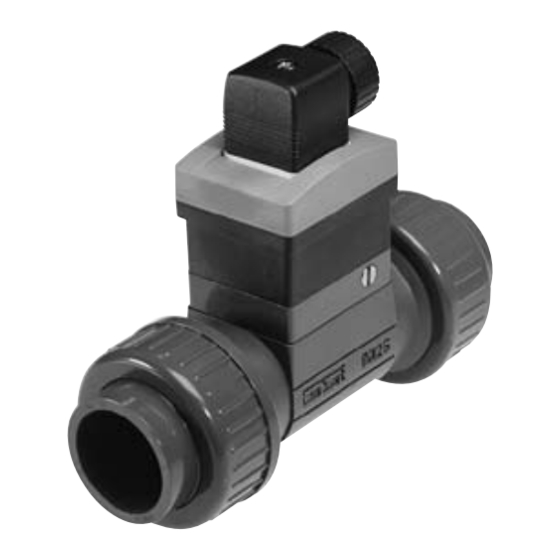
All manuals and user guides at all-guides.com Durchfluss-Sensor 8030 BESCHREIBUNG 2.1 Aufbau und Messprinzip Der Durchfluss-Sensor 8030 besteht aus einem Elektronikmodul SE30 SE30 und einem Fitting S030 mit integiertem Flügelrad. In Bewegung gesetzt durch die strömende Flüssigkeit, erzeugt das S030 Flügelrad im Messwertaufnehmer eine Mess-Frequenz f, die der...
All manuals and user guides at all-guides.com Durchfluss-Sensor 8030 TECHNISCHE DATEN Allgemeine Daten Rohrdurchmesser DN6 bis DN65 (1/4’’ bis 2’’1/2), der geeignete Durchmesser wird mittels den Durchfluss/Rohrnennweite/Strömungsgeschwindigkeit Diagramme im Anhang Flüssigkeitstemperatur max. 100 °C, Edelstahl, Messing, PVDF 80 °C, PP 50 °C, PVC...
Seite 78
300 Hz, Spitze-Spitze-Spannung von ungef. 2,8 mV/Hz unter einer 50 kΩ Bürde (Frequenz = K Faktor x Durchfluss ; der Wert des K Faktors befindet sich in der Betriebsanleitung des Fittings) Kabellänge max. 10 m, abgeschirmt Kabelquerschnitt max. 1.5 mm 8030...
Seite 79
All manuals and user guides at all-guides.com Durchfluss-Sensor 8030 TECHNISCHE DATEN Elektrische Daten (Fortsetzung) Hall-Effekt Puls-Version Versorgungsspannung 12-36 VDC Stromaufnahme max. 30 mA (ohne Bürde) Schutz gegen Falschpolung vorhanden Schutz gegen Spannungsspitzen vorhanden Ausgangsdaten NPN und PNP Transistor, Open Kollektor, 100 mA max., NPN-Ausgang: 0,2-36 VDC und PNP-Ausgang: Versorgungsspannung (siehe Beispiel im Anhang) Frequenz bis 300 Hz (Frequenz = K Faktor x Durchfluss ;...
Seite 81
Edelstahl (316L/DIN1.4404), Messing, PVC, PP, PVDF - Flügelrad PVDF (PP nach Anfrage) - Achse und Lager Keramik Umgebungs-Bedingungen Umgebungs- und Lager- Temperatur -15 °C bis +60 °C Relative Luftfeuchtigkeit < 80%, nicht kondensiert Schutzklasse des Gehäuses IP65, mit eingestecktem und festgeschraubtem Gerätestecker 8030...
Seite 82
All manuals and user guides at all-guides.com Durchfluss-Sensor 8030 TECHNISCHE DATEN Abmessungen (mm) EN 175301-803 DN S030 H (mm) 95.5 95.5 100.5 105.5...
Seite 83
All manuals and user guides at all-guides.com 8030...
All manuals and user guides at all-guides.com Durchfluss-Sensor 8030 INSTALLATION 4.1 Allgemeine Hinweise Überprüfen Sie immer die chemische Kompatibilität der Sensor- Werkstoffe mit denen das Gerät in Kontakt kommt. Für weitere Auskünfte, steht Ihnen Bürkert zur Verfügung. 4.2 Einbau in die Rohrleitung Das Elektronikmodul SE30 ist für den Einbau in die Rohrleitung mit einem...
Spannung oder Frequenz installiert werden. - Wenn eine kombinierte Installation unumgänglich ist, sollten ein Mindestabstand von 30 cm eingehalten werden. - Verwenden Sie eine Spannungsversorgung guter Qualität (gefiltert und stabilisiert). Obligatorisch ist eine angepasste Sicherung für die Stromversorgung zu installieren. 8030...
- Das Innenteil [3] zurückstecken. - Die Kabeldurchführung [5] festschrauben. - Die Dichtung [4] zwischen dem Stecker und dem Steckverbinder des Sensors 8030 einsetzen. - Den Stecker an den Sensor 8030 anschließen. - Die Schraube [1] festschrauben. 4.3.2 Verkabelung der Ausgangsfrequenz: Sinus-Version (Spulenausgang) Sensor Empfänger...
4.3.3 Verkabelung der Ausgangsfrequenz (NPN und PNP- Transistorausgänge: Puls-Version (Hall-Effekt Sensor) Sensor Empfänger Sensor Empfänger Ausgang Ausgang Last Last NPN-Transistor- Ausgang PNP-Transistor-Ausgang PNP-Transistor-Ausgang Verkabelung als NPN / PNP (12-30 VDC) Transistorausgang des Steckers NPN-Transistor- Ausgang 0 VDC Erden Sie die beiden Enden des Kabels. 8030...
All manuals and user guides at all-guides.com Durchfluss-Sensor 8030 INSTALLATION 4.3.4 Verkabelung der Ausgangsfrequenz (NPN- Transistorausgang): Puls-Version (Low Power Hall-Effekt Sensor) Sensor Empfänger NPN-Transistor- Ausgang Ausgang Last Nicht belegt Verkabelung als NPN (12-30 VDC) Transistorausgang des Steckers EN NPN-Transistor- Ausgang 0 VDC Erden Sie die beiden Enden des Kabels.
Seite 90
All manuals and user guides at all-guides.com 8030...
All manuals and user guides at all-guides.com Durchfluss-Sensor 8030 ANHANG 5.2 Typschildangaben des Sensors SE30 FLOW:SE30/8030 HALL LP OPEN COLLECTOR NEW VERSION S-N:59037 00423914 W45LG Sensor-Typ Sensordaten und eventuell, Betriebsspannung Ausgangsdaten «NEW VERSION»-Angabe bei einem SE30 Hall und Hall Low Power...
All manuals and user guides at all-guides.com 5.3 Anschlussmöglichkeiten mit der Sinus-Version Typ 8034 Batterie Wandmontage Typ 8025 Totalisator Batterie Wandmontage Typ 8023 4-20 mA- Ausgangsmodul 8030 - Durchfluss-Sensor Sinusausgang 8030...
All manuals and user guides at all-guides.com Durchfluss-Sensor 8030 ANHANG 5.4 Anschlussmöglichkeiten mit der Puls-Version (Hall-Effekt Sensor) Typ 8025 Batch Typ 8025 Universal (Low Flow) Wandmontage oder Wandmontage oder Schaltschrank Schaltschrank Typ 8032 Wandmontage Typ 8021 P L C 8030 -...
Typ 8032 Wandmontage Typ 8023 Schließen Sie nur eine neue Ausführung des Transmitters 8023 an eine neue Ausführung des Sensors 8030 Low Power (Bestell- 8030 - Nr. 423914). Siehe «NEW Durchfluss-Sensor VERSION»-Angabe auf den Typenschilder beider Geräten. Pulsausgang (Hall Low Power)
All manuals and user guides at all-guides.com Durchfluss-Sensor 8030 ANHANG 5.6 Anschlussbeispiele 24 VDC Anschluss des 8030 an ein Durchflussregler 8623-2. 8623-2 8030 24 VDC TopControl 8630 Anschluss des 8030 Hall an ein auf ein Membranventil 8030 2031 montierten TopControl 8630 mit 2031 Kabelverschraubung.
Seite 100
All manuals and user guides at all-guides.com PNP (2) Anschluss des 8030, Puls-Version (Transistorausgänge NPN (2) und PNP ) an ein 8030 Transmitter 8025 Low Low Flow Flow, Schaltschrank- Ausführung, 13-30 VDC. (1) Ist keine direkte Erdung möglich, schließen Relais-Anschluss (Option)
Seite 101
All manuals and user guides at all-guides.com Durchfluss-Sensor 8030...