Inhaltsverzeichnis
Werbung
Verfügbare Sprachen
Verfügbare Sprachen
Quicklinks
Werbung
Inhaltsverzeichnis

Verwandte Anleitungen für Eliwell DR4000 series


Inhaltszusammenfassung für Eliwell DR4000 series
- Seite 1 DR4000 DR4020-4022 • Temperature controllers and process controllers. • Regolatori di temperatura e regolatori di processo. • Reguladores de temperatura y reguladores de proceso • Temperatur- und Prozessregler. Regulateurs de temperature et regulateurs de processus. •...
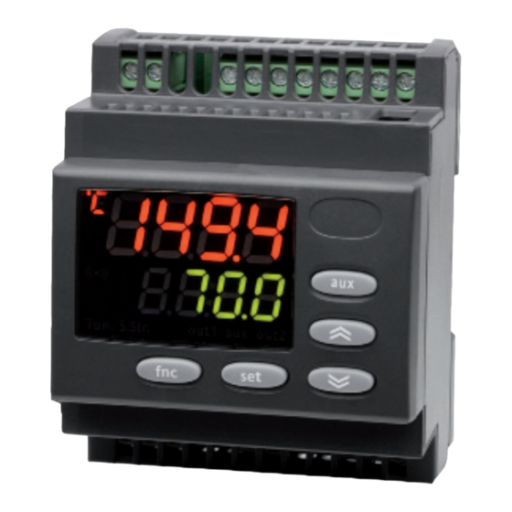
- Seite 3 ENGLISH DR4000 Universal Controller Temperature controllers and process controllers. Process value(PV): Used to display the process value, and the labels of parameters, alarms and functions. Set value (SV): Tun. S.Str out1 out2 Used to display the setpoint, parameter values, function statuses and other statuses.
-
Seite 4: Keys & Leds
KEYS & LEDs °C LED press and release Steadily lit: °C setting (dro =0) Scrolls through menu items Off: when output not active Increases values on the display °F LED Hold down for at least 5 sec Steadily lit: °F setting (dro =1) User-configurable function Off: when output not active... - Seite 5 MECHANICAL INSTALLATION and DIMENSIONS The device is designed for wall or panel mounting on DIN rails. Make a hole 70x45 mm and insert the device, securing it with the fixing hooks provided. Do not install the device in places subject to high humidity and/or dirt; it is intended for use in sites with ordinary or normal levels of pollution.
-
Seite 6: "Machine Status" Menu
"MACHINE STATUS" MENU The following procedure is to be followed in order to set the 2 setpoint values in the device, SEt1 and SEt2. Tun. S.Str out1 out2 Tun. S.Str out1 out2 Tun. S.Str out1 out2 Tun. S.Str out1 out2 2) Label SEt1 is 3) Use the UP and 4) When the 'set' or... - Seite 7 PASSWORDS Password “PA1”: access to “User Menu” parameters. The password is disabled by default (PS1=0). To enable it (PS1≠0): hold down the key for at least 5 seconds and then until finding label PS1. scroll through the parameters with and ...
- Seite 8 UNICARD / COPY CARD The Unicard/Copy Card is an accessory connected to the TTL serial port used for quick programming of the device parameters (upload and download a parameter map to one or more devices of the same type). The upload (label UL), download (label dL) and Unicard/copy card formatting (label Fr) operations are performed as explained below: Tun.
-
Seite 9: "Functions" Menu
"FUNCTIONS" MENU The Functions Menu contains a number of special functions that can be used to configure and manage the device: the Functions Folder and the Alarms Folder (if at least one alarm is present). After pressing the key, you can scroll through the two folders in the menu (FnC and ALAr) using the keys. - Seite 10 "USER" Menu To access the “USER Menu”, hold down the key for more than 5 seconds. If enabled, the “PA1” access PASSWORD will be requested (see “PASSWORD” section). Press the key to edit the parameter values. The display will show the first parameter in the menu (e.g. parameter “dF1”).
- Seite 11 "USER" Menu PARAMETERS table Parameter DESCRIPTION RANGE DR4020 DR4022 Relay 1 activation differential 0.1 ... 30.0 °C/°F Control mode selection. H = Hot; C = Cold flag Response band above SEtpoint SEt1 0.0 ... 30.0 °C/°F Relay 2 activation differential 0.1 ...
-
Seite 12: "Installer" Menu
“INSTALLER” Menu To access the "INSTALLER Menu", hold down the key for more than 5 seconds. Using keys, display parameter “PA2” and select it by pressing the key. If enabled, enter the “PA2” access PASSWORD (see “PASSWORD” section). The display will show the first folder in the ADVANCED menu (e.g. folder “rE1”). By pressing keys you can scroll through all the folders in the "INSTALLER"... - Seite 13 "INSTALLER" Menu PARAMETERS table PAR. DESCRIPTION U.M. RANGE MODEL DR4020 DR4022 SEt1 Temperature control SEtpoint 1. °C/°F LS1 ... HS1 SEt2 Temperature control SEtpoint 2. °C/°F LS2 ... HS2 CONTROLLER 1 (Folder rE1) Setpoint 1 Offset. Temperature value to be added algebraically to the setpoint if °C/°F -30.0...30.0 reduced set enabled (Economy function).
- Seite 14 PAR. DESCRIPTION U.M. RANGE MODEL DR4020 DR4022 Start delay. The indicated time must elapse between the request for activation of 0 ... 255 the controller relay and switch-on. Delay time after switch-off. The indicated time must elapse between deactivation 0 ... 255 of the controller 1 relay and the next switch-on.
- Seite 15 PAR. DESCRIPTION U.M. RANGE MODEL DR4020 DR4022 TcJ/TcK -40.0 -40.0 PTC/NTC/PT1000 -200 -200 °C/°F LdL ... HS2 Minimum value assignable to SEtpoint “SEt2” PT100 -200 -200 TcJ/TcK 2910 2910 OUT 2 Maximum temperature alarm LA2 ... 2910 PTC/NTC/PT1000 2910 2910 °C/°F PT100 (see ‘MAX/MIN Temperature Alarms’...
- Seite 16 PAR. DESCRIPTION U.M. RANGE MODEL DR4020 DR4022 ANALOGUE OUTPUT (Folder AnOu) 020/420/001 Analogue output operating mode: 005/010 020 = 0...20mA; 420 = 4...20mA; 001 = 0...1V; 005 = 0...5V; 010 = 0...10V. Analogue output operating mode: diS = output disabled; ro = read out.
- Seite 17 PAR. DESCRIPTION U.M. RANGE MODEL DR4020 DR4022 CYCLIC CONTROLLER (Folder cLc) Con ON time for cyclic controller output 0 ... 255 CoF OFF time for cyclic controller output 0 ... 255 ALARMS (Folder ALAr) Parameter HA1/2 and LA1/2 modes, as absolute temperature values or as differential flag Abs/reL compared with the Setpoint.
- Seite 18 PAR. DESCRIPTION U.M. RANGE MODEL DR4020 DR4022 DISPLAY (Folder diSP) Keypad lock and Setpoint modification. It is still possible to access parameter programming and edit parameters, including LOCK status. flag (y = Keypad LOCKED; n = Keypad UNLOCKED). Password 1. When enabled (PS1 ≠ 0), this password provides access to level 1 0 ...
- Seite 19 PAR. DESCRIPTION U.M. RANGE MODEL DR4020 DR4022 TcJ/TcK Select probe display type. PTC/NTC/PT1000 TcJ/TcK/PTC/NTC/PT1000/PT100 models: C = °C, F = °F. flag PT100 V/I models: C/F/bAr/rH/ C = °C, F = °F, bAr = Bar; rH = %RH, PA = Pascal, PSi = PSi, null = empty PA/PSi/null View basic status of the display.
- Seite 20 PAR. DESCRIPTION U.M. RANGE MODEL DR4020 DR4022 TcJ/TcK PTC/NTC/PT1000 H03 Lower input current/voltage limit: PT100 -1999...9999 TcJ/TcK PTC/NTC/PT1000 Higher input current/voltage limit PT100 -1999... 999 H06 Key or aux/light digital input active with device OFF; n= not active; y= active. flag Standby mode: 0 = only display switches off;...
- Seite 21 PAR. DESCRIPTION U.M. RANGE MODEL DR4020 DR4022 H25 Enable buzzer (only if buzzer is present). n = not enabled; y = enabled flag UP key configuration. 0 = disabled; 1 = SOFT START; 2 = Setpoint Offset; 3 = Cyclic Controller; 0 ...
- Seite 22 TECHNICAL SPECIFICATIONS (EN 60730-2-9) Use: operating (not safety) device for incorporation Mounting: on DIN rail (Omega 3) or panel mounting, with 70x45mm opening. Type of action: Pollution class: Material class: IIIa Overvoltage category: Nominal pulse voltage: 2500V Temperature: Use: -5.0 … +55.0°C - Storage: -20.0 … +85.0°C Power supply: Switching: 100 ...
-
Seite 23: Further Information
FURTHER INFORMATION Input Characteristics Display range: See Probes Table See Probes Table Accuracy: Resolution: See Probes Table Analogue Inputs: 1 input selectable by parameter H00 Output Characteristics Digital Outputs: OUT 1: 1 SPDT 8(3)A max 250 Va OUT 2: 1 SPDT 8(3)A max 250 Va Output V/I: 0-1V, 0-5V, 0-10V, 0...20mA e 4...20mA (See Max loads table) Analogue Output*: Buzzer output... - Seite 24 WIRING DIAGRAM DR4020 PTC/ Pt1000 22 23 24 22 23 24 out2 out2 Pt100 22 23 24 22 23 24 DR 4020 DR 4020 100...240 Va 12...24 Va/12...36 Vc I (0...20/ V (0...5/ 4...20mA) 0...10Vc) V (0...1Vc) 13 14 15 22 23 24 13 14 15 19 20 21...
- Seite 25 WIRING DIAGRAM DR4020 10 11 12 10 11 12 PTC/ Pt1000 22 23 24 22 23 24 D.I. D.I. RS-485 RS-485 out2 out2 Pt100 22 23 24 22 23 24 DR 4022 DR 4022 100...240 Va 12...24 Va/12...36 Vc I (0...20/ V (0...5/ 4...20mA) 0...10Vc)
- Seite 26 MAX LOADS TABLE maximum loads that can be driven by the analog output: output type permissible load 0-1 V 20mA with minimum load impedance 50 Ohm 0-5 V 20mA with minimum load impedance 250 Ohm 0-10 V 20mA with minimum load impedance 500 Ohm 0-20 mA 350 Ohm 4-20 mA...
- Seite 27 TRANSDUCER CONNECTION EXAMPLES CAUTION: wire colours are guideline. Check the correct connection diagram on the probe label.
- Seite 28 ALARMS Label Fault Cause Effects Remedy • Label E1 displayed. • measured values outside operating • Alarm icon permanently on • check probe type (see H00) Probe 1 faulty range • Controller disabled max/min alarms • check probes wiring (Regulation) •...
- Seite 29 MAX/MIN TEMPERATURE ALARMS Absolute temperature Temperature relative value (Att=0) to setpoint value (Att=1) LA1/LA2 HA1/HA2 SP1+ LA1/SP2 + LA2 SP1+ HA1/SP2 + HA2 Minimum temperature Temp. ≤ LA1/2 (LA1/2 with sign) Temp. ≤ Set + LA1/2 * alarm Maximum temperature Temp.
- Seite 30 CONTROLLER ON-OFF Model DR4020 and DR4022 has two ON/OFF type controllers that can be configured by the user with parameter H01: • H01=4, 5 threshold controller • H01=6 controller with window Independent ON-OFF control diagram. The two outputs provide control as though they were completely independent of each other. HC1 HC2 H01 Type of Setting independent setpoint interdependent setpoints...
- Seite 31 SOFT START CONTROLLER Note: The SOFT START function is selectable with a key press or by means of a function. The Soft Start controller can be used to set the temperature gradient over which a given setpoint is reached within a predefined time. In fact, with this function a gradual increase of the control Setpoint is obtained automatically, from value Ta (ambient temperature at activation) to the value actually set on the display;...
-
Seite 32: The Controller Is Inactive During Start-Up/Switch-On (Controller Off) Or When In Standby (Based On The Value Of H08)
AUXILIARY CONTROLLER (AUX) The auxiliary controller can be activated by key press (parameter H31=4 o H32=4): in this case the controller must be managed as aux by setting parameters H21(H22)=4. This function is used to energise the relay if it was de-energised, or vice versa. The relay state is stored in order to maintain correct operation in the event of a power failure. -
Seite 33: Electrical Connections
LIABILITY AND RESIDUAL RISKS ELIWELL CONTROLS SRL declines all liability for damage due to: - installation/use other than expressly specified and, in particular, in conflict with the safety prescriptions set down in regulations and/or specified in this document - use on panels that do not provide adequate protection against electric shocks, water or dust in the adopted mounting conditions;... -
Seite 34: Permitted Use
This document is the exclusive property of ELIWELL CONTROLS SRL and may not be reproduced or circulated without the express permission of ELIWELL CONTROLS. While all possible care has been taken to ensure the accuracy of this document, ELIWELL CONTROLS SRL cannot accept liability for any damage resulting from its use. The same applies to any person or company involved in preparing and editing this document. - Seite 35 ITALIANO DR4000 Universal Controller Regolatori di temperatura e regolatori di processo. Process value (PV): Utilizzato per visualizzare il valore del processo, le label dei parametri, degli allarmi e delle funzioni. Set value (SV): Tun. S.Str out1 out2 Utilizzato per visualizzare il setpoint, il valore dei parametri, lo stato delle funzioni, gli stati.
- Seite 36 TASTI & LED Led °C Premere e rilasciare Acceso fisso: impostazione in °C (dro = 0) Scorre le voci del menu Off: altrimenti Incrementa i valori a display Led °F Premere per almeno 5 sec Acceso fisso: impostazione in °F (dro = 1) Funzione configurabile dall’utente Off: altrimenti...
- Seite 37 MONTAGGIO MECCANICO e DIMENSIONI Il dispositivo è concepito per il montaggio su guida DIN, a parete o a pannello. Praticare un foro da 70x45 mm e introdurre lo strumento fissandolo con gli appositi ganci di fissaggio. Evitare di montare lo strumento in luoghi soggetti ad alta umidità e/o sporcizia; esso, infatti, è...
- Seite 38 MENU “STATO MACCHINA” Di seguito è descritta la procedura necessaria ad impostare i 2 valori di setpoint presenti nello strumento SEt1 e SEt2. Tun. S.Str out1 out2 Tun. S.Str out1 out2 Tun. S.Str out1 out2 Tun. S.Str out1 out2 1) Premere e rilasciare 2) Sul display PV 3) Usando i tasti ‘UP’...
- Seite 39 PASSWORD Password “PA1”: consente l’accesso ai parametri del “Menu Utente”. Di default la password non é abilitata (PS1=0). Per abilitarla (PS1≠0): premere per oltre 5 secondi il tasto e scorrere i fino a trovare la label PS1. parametri con Per modificarne il valore, premere il tasto .
- Seite 40 UNICARD / COPY CARD La Unicard/Copy Card è un accessorio che, connesso alla porta seriale di tipo TTL, consente la programmazione rapida dei parametri dello strumento (carico e scarico di una mappa parametri in uno o più strumenti dello stesso tipo). Le operazioni di upload (label UL), download (label dL) e di formattazione della chiavetta (label Fr) si effettuano nel seguente modo: Tun.
- Seite 41 MENU “FUNZIONI” Il “Menu Funzioni” contiene alcune particolari funzionalità, utili all’impostazione e alla gestione dello strumento: la Cartella Funzioni e la Cartella Allarmi (se è presente almeno un allarme). Una volta premuto il tasto è possibile scorrere le due cartelle presenti nel menu (FnC e ALAr) mediante l’utilizzo dei tasti Tun.
- Seite 42 Menu “UTENTE” Per accedere al “Menu UTENTE” premere per oltre 5 secondi il tasto . Se previsto, verrà richiesta una PASSWORD di accesso “PA1” (vedi paragrafo “PASSWORD”). Per modificare il valore dei parametri, premere il tasto . Il display visualizzerà il primo parametro del menu (es: parametro “dF1”).
- Seite 43 Tabella PARAMETRI Menu “UTENTE” PAR. DESCRIZIONE RANGE U.M. DR4020 DR4022 dF1 Differenziale di intervento del relè 1 0,1 ... 30,0 °C/°F HC1 Selezione modo di regolazione. H = Caldo; C = Freddo flag db1 Banda di intervento sopra il SEtpoint SEt1 0,0 ...
- Seite 44 Menu “INSTALLATORE” Per accedere al “Menu INSTALLATORE”, premere per oltre 5 secondi il tasto . Mediante i tasti visualizzare il parametro “PA2” e selezionarlo premendo il tasto Se abilitata, inserire la PASSWORD di accesso “PA2” (vedi paragrafo “PASSWORD”). Il display visualizzerà la prima cartella del menu “ADVANCE” (es: cartella “rE1”). Agendo sui tasti si possono scorrere tutte le cartelle del menu “INSTALLATORE”: 5 sec Tun.
- Seite 45 Tabella PARAMETRI Menu “INSTALLATORE” PAR. DESCRIZIONE U.M. RANGE MODELLO DR4020 DR4022 SEt1 SEtpoint di regolazione 1 della Temperatura. °C/°F LS1 ... HS1 TUTTI SEt2 SEtpoint di regolazione 2 della Temperatura. °C/°F LS2 ... HS2 TUTTI REGOLATORE 1 (Cartella rE1) Offset Setpoint 1. Valore di temperatura da sommare algebricamente al setpoint °C/°F -30,0 ...
- Seite 46 PAR. DESCRIZIONE U.M. RANGE MODELLO DR4020 DR4022 Ritardo all’ a ccensione. Fra la richiesta di accensione del relè del regolatore e 0 ... 255 TUTTI l’ a ccensione deve trascorrere il tempo indicato. Tempo ritardo dopo lo spegnimento. Fra lo spegnimento del relè del regolatore 1 0 ...
- Seite 47 PAR. DESCRIZIONE U.M. RANGE MODELLO DR4020 DR4022 TcJ/TcK -40,0 -40,0 PTC/NTC/PT1000 -200 -200 LS2 Valore minimo attribuibile al SEtpoint “SEt2” °C/°F LdL ... HS2 PT100 -200 -200 TcJ/TcK 2910 2910 Allarme di massima OUT 2 LA2 ... 2910 PTC/NTC/PT1000 2910 2910 °C/°F (Vedi schema ‘Allarmi di Temperatura MAX/MIN’)
- Seite 48 PAR. DESCRIZIONE U.M. RANGE MODELLO DR4020 DR4022 USCITA ANALOGICA (Cartella AnOu) Modo di funzionamento uscita analogica: 020/420/001 TUTTI 020 = 0...20mA; 420 = 4...20mA; 001 = 0...1V; 005 = 0...5V; 010 = 0...10V. 005/010 Modo di funzionamento uscita analogica: diS = uscita disabilitata; ro = read out.
- Seite 49 PAR. DESCRIZIONE U.M. RANGE MODELLO DR4020 DR4022 REGOLATORE CICLICO (Cartella cLc) Con Tempo di ON uscita regolatore ciclico 0 ... 255 TUTTI CoF Tempo di Off uscita regolatore ciclico 0 ... 255 TUTTI ALLARMI (Cartella ALAr) Modalità parametri HA1/2 e LA1/2, intesi come valore assoluto di temperatura o flag Abs/reL TUTTI...
- Seite 50 PAR. DESCRIZIONE U.M. RANGE MODELLO DR4020 DR4022 DISPLAY (Cartella diSP) Blocco tastiera e modifica Setpoint. Rimane comunque la possibilità di entrare in programmazione parametri e modificarli, compreso lo stato di LOC. flag TUTTI (y = Tastiera BLOCCATA; n = Tastiera LIBERA). Password 1.
- Seite 51 PAR. DESCRIZIONE U.M. RANGE MODELLO DR4020 DR4022 TcJ/TcK Seleziona il tipo di visualizzazione della sonda. PTC/NTC/PT1000 Modelli TcJ/TcK/PTC/NTC/PT1000/PT100: flag C = °C, F = °F. PT100 Modelli V/I: C/F/bAr/rH/ C = °C, F = °F, bAr = Bar; rH = %RH, PA = Pascal, PSi = PSi, null = vuoto PA/PSi/null Visualizzazione dello stato fondamentale del display.
- Seite 52 PAR. DESCRIZIONE U.M. RANGE MODELLO DR4020 DR4022 TcJ/TcK PTC/NTC/PT1000 H03 Limite inferiore ingresso corrente/tensione: PT100 -1999...9999 TcJ/TcK PTC/NTC/PT1000 H04 Limite inferiore ingresso corrente/tensione: PT100 -1999... 9999 H06 Tasto o digital input aux/luce attivi a strumento in OFF: n=non attivi; y=attivi; flag TUTTI Modalità...
- Seite 53 PAR. DESCRIZIONE U.M. RANGE MODELLO DR4020 DR4022 H25 Abilitazione buzzer (solo se buzzer presente). n = non abiliato; y = abilitato flag TUTTI Configurazione tasto UP. 0 = disabilitato; 1 = SOFT START; 2 = Offset setpoint; 3 = Regolatore Ciclico; 0 ...
- Seite 54 DATI TECNICI (EN 60730-2-9) Utilizzo: dispositivo di funzionamento (non di sicurezza) da incorporare Montaggio: su guida DIN (Omega 3) o a pannello con dima di foratura 70x45. Tipo di azione: Grado di inquinamento: Gruppo del materiale: IIIa Categoria di sovratensione: Tensione impulsiva nominale: 2500V Temperatura:...
-
Seite 55: Caratteristiche Ingressi
ULTERIORI INFORMAZIONI Caratteristiche Ingressi Range di visualizzazione: Vedi Tabella Sonde Vedi Tabella Sonde Accuratezza: Risoluzione: Vedi Tabella Sonde Ingressi Analogici: 1 ingresso selezionabile da parametro H00 Caratteristiche Uscite Uscite Digitali: OUT 1: 1 SPDT 8(3)A max 250 Va OUT 2: 1 SPST 8(3)A max 250 Va Uscita V/I: 0-1V, 0-5V, 0-10V, 0...20mA e 4...20mA (Vedi Tabella carichi max) Uscita Analogica*: Uscita Buzzer... - Seite 56 SCHEMA ELETTRICO DR4020 PTC/ Pt1000 22 23 24 22 23 24 out2 out2 Pt100 22 23 24 22 23 24 DR 4020 DR 4020 100...240 Va 12...24 Va/12...36 Vc I (0...20/ V (0...5/ 4...20mA) 0...10Vc) V (0...1Vc) 13 14 15 22 23 24 13 14 15 19 20 21...
- Seite 57 SCHEMA ELETTRICO DR4022 10 11 12 10 11 12 PTC/ Pt1000 22 23 24 22 23 24 D.I. D.I. RS-485 RS-485 out2 out2 Pt100 22 23 24 22 23 24 DR 4022 DR 4022 100...240 Va 12...24 Va/12...36 Vc I (0...20/ V (0...5/ 4...20mA) 0...10Vc)
- Seite 58 TABELLA CARICHI MAX carichi massimi pilotabili dall’uscita analogica: tipo uscita carico pilotabile 0-1 V 20mA con minima resistenza di carico 50 Ohm 0-5 V 20mA con minima resistenza di carico 250 Ohm 0-10 V 20mA con minima resistenza di carico 500 Ohm 0-20 mA 350 Ohm 4-20 mA...
- Seite 59 ESEMPI DI CONNESSIONE TRASDUTTORI ATTENZIONE!: il colore dei fili è indicativo. Verificare sull’etichetta della sonda lo schema corretto di connessione.
-
Seite 60: Risoluzione Problema
ALLARMI Guasto Causa Effetti Risoluzione Problema Label • Visualizzazione label E1 • controllare il tipo di sonda • lettura di valori al di fuori del range • Icona Allarme Fissa (par. H00) Sonda1 guasta di funzionamento • Disabilitazione regolatore allarmi max/min •... -
Seite 61: Temperatura In Valore Assoluto (Att=0)
ALLARMI DI TEMPERATURA MAX/MIN Temperatura in valore Temperatura in valore Assoluto (Att=0) Relativo al setpoint (Att=1) LA1/LA2 HA1/HA2 SP1+ LA1/SP2 + LA2 SP1+ HA1/SP2 + HA2 Allarme di minima Temp. ≤ LA1/2 (LA1/2 con segno) Temp. ≤ Set + LA1/2 * temperatura Allarme di massima Temp. - Seite 62 REGOLATORE ON-OFF I modelli DR4020 e DR4022 hanno 2 regolatori di tipo ON/OFF che sono configurabili da utente mediante il parametro H01: • H01=4, 5 regolatore di soglia • H01=6 regolatore a finestra Schema regolazione ON-OFF indipendente. Le due uscite regolano come fossero completamente indipedenti. HC1 HC2 H01 Tipo di Regolazione setpoint indipendente setpoint interdipendenti...
- Seite 63 REGOLATORE SOFT START Nota: La funzione di SOFT START è selezionabile da tasto oppure da funzione. Il regolatore Soft Start permette di impostare il gradiente di temperatura con cui raggiungere un determinato setpoint in un tempo predefinito. Mediante questa funzione, infatti, si ottiene, automaticamente, un aumento progressivo del Setpoint di regolazione dal valore Ta (Temperatura ambiente al momento dell’accensione) al valore effettivamente impostato a display;...
- Seite 64 REGOLATORE AUSILIARIO (AUX) E’ possibile attivare il regolatore ausiliario mediante tasto (parametro H31=4 o H32=4): in questo caso si deve prevedere il comando del regolatore come aux tramite i parametri H21(H22)=4. Questa funzione permette di attivare il relé se era diseccitato o eccitarlo nel caso opposto. Lo stato viene memorizzato, per preservare il funzionamento corretto, in caso di black-out.
-
Seite 65: Connessioni Elettriche
TTL separati dai cavi di potenza. RESPONSABILITA’ E RISCHI RESIDUI ELIWELL CONTROLS SRL non risponde di eventuali danni derivanti da: - installazione/uso diversi da quelli previsti e, in particolare, difformi dalle prescrizioni di sicurezza previste dalle normative e/o date con il presente;... -
Seite 66: Uso Consentito
DECLINAZIONE DI RESPONSABILITA’ La presente pubblicazione è di esclusiva proprietà di ELIWELL CONTROLS SRL la quale pone il divieto assoluto di riproduzione e divulgazione se non espressamente autorizzata da ELIWELL CONTROLS SRL stessa. Ogni cura è stata posta nella realizzazione di questo documento; tuttavia ELIWELL CONTROLS SRL non può... - Seite 67 ESPAÑOL DR4000 Universal Controller Reguladores de temperatura y reguladores de proceso. Process value (PV): Se utiliza para visualizar el valor del proceso, las etiquetas de los parámetros, de las alarmas y de las funciones. Set value (SV): Tun. S.Str out1 out2 Se utiliza para visualizar el setpoint, el valor de los parámetros, el estado...
- Seite 68 TECLAS & LEDS Led °C Pulsar y soltar Encendido fijo: configuración en °C (dro = 0) Se desplaza por los items del menú Off: en los demás casos Aumenta los valores en el display Led °F Pulse durante al menos 5 seg Encendido fijo: configuración en °F (dro = 1) Función configurable por el usuario Off:...
- Seite 69 MONTAJE MECÁNICO Y DIMENSIONES El dispositivo se ha diseñado para su montaje en guía DIN, sobre pared o panel. Realice un agujero de 70x45 mm e introduzca el instrumento sujetándolo con los correspondientes ganchos de fijación. Evite montar el instrumento en lugares expuestos a una alta humedad y/o suciedad;...
- Seite 70 MENú “ESTADO MÁqUINA” A continuación se describe el procedimiento necesario para configurar los 2 valores de setpoint presentes en el instrumento SEt1 y SEt2. Tun. S.Str out1 out2 Tun. S.Str out1 out2 Tun. S.Str out1 out2 Tun. S.Str out1 out2 1) Pulsar y soltar la tecla 2) En el display PV se 3) Usando las teclas...
- Seite 71 CONTRASEÑA Contraseña “PA1”: permite acceder a los parámetros del “Menú Usuario”. Por defecto la contraseña no está habilitada (PS1=0). Para habilitarla (PS1≠0): pulse durante más de 5 segundos hasta encontrar la etiqueta PS1. la tecla y desplácese por los parámetros con Para modificar su valor, pulse la tecla .
- Seite 72 UNICARD / COPY CARD La Unicard/Copy Card es un accesorio que, conectado al puerto serial de tipo TTL, permite la programación rápida de los parámetros del instrumento (carga y descarga de un mapa de parámetros a uno o más instrumentos del mismo tipo).Las operaciones de carga (etiqueta UL), descarga (etiqueta dL) y de formateo de la llave (label Fr) se efectúan del siguiente modo: Tun.
- Seite 73 MENú “FUNCIONES” El “Menú Funciones” contiene funciones especiales útiles para la configuración y la gestión del instrumento: la Carpeta Funciones y la Carpeta Alarmas (si hay al menos una alarma). Una vez pulsada la tecla se pueden recorrer las dos carpetas presentes en el menú (FnC y ALAr) utilizando las teclas Tun.
- Seite 74 MENú “USUARIO” Para acceder al “Menú Usuario” pulse durante más de 5 segundos la tecla . Si se ha previsto, se le pedirá una CONTRASEÑA de acceso “PA1” (véase apartado “Contraseña”). Para modificar el valor de los parámetros, pulse la tecla .
- Seite 75 TABLA PARÁMETROS MENú “USUARIO” PAR. DESCRIPCIÓN RANGO U.M. DR4020 DR4022 dF1 Diferencial de intervención del relé 1 0,1 ... 30,0 °C/°F HC1 Selección del modo de regulación. H = Calor; C = Frío opción db1 Banda de intervención por encima del SEtpoint SEt1 0,0 ...
- Seite 76 MENú “INSTALADOR” Para acceder al “Menú Instalador”, pulse durante más de 5 segundos la tecla . Mediante las teclas visualice el parámetro “PA2” y selecciónelo pulsando la tecla Si está habilitada, introduzca la contraseña de acceso “PA2” (véase apartado “CONTRASEÑA”). El display visualizará...
- Seite 77 TABLA PARÁMETROS MENú “INSTALADOR” PAR. DESCRIPCIÓN U.M. RANGO MODELO DR4020 DR4022 SEt1 SEtpoint de regulación 1 de la Temperatura. °C/°F LS1 ... HS1 TODOS SEt2 SEtpoint de regulación 2 de la Temperatura. °C/°F LS2 ... HS2 TODOS REGULADOR 1 (Carpeta rE1) Offset Setpoint 1.
- Seite 78 PAR. DESCRIPCIÓN U.M. RANGO MODELO DR4020 DR4022 Retardo en el encendido. Entre la petición de encendido del relé del regulador y el 0 ... 255 TODOS encendido ha de transcurrir el tiempo indicado. Tiempo retardo tras el apagado. Entre el apagado del relé del regulador 1 y el 0 ...
- Seite 79 PAR. DESCRIPCIÓN U.M. RANGO MODELO DR4020 DR4022 TcJ/TcK -40,0 -40,0 PTC/NTC/PT1000 -200 -200 LS2 Valor mínimo que se le atribuye al SEtpoint “SEt2” °C/°F LdL ... HS2 PT100 -200 -200 TcJ/TcK 2910 2910 Alarma de máxima OUT 2 LA2 ... 2910 PTC/NTC/PT1000 2910 2910...
- Seite 80 PAR. DESCRIPCIÓN U.M. RANGO MODELO DR4020 DR4022 SALIDA ANALÓGICA (Carpeta AnOu) Modo de funcionamiento de la salida analógica: 020/420/001 núm TODOS 020 = 0...20mA; 420 = 4...20mA; 001 = 0...1V; 005 = 0...5V; 010 = 0...10V. 005/010 Modo de funcionamiento de la salida analógica: diS = salida deshabilitada;...
- Seite 81 PAR. DESCRIPCIÓN U.M. RANGO MODELO DR4020 DR4022 REGULADOR CÍCLICO (Carpeta cLc) Con Tiempo de ON salida regulador cíclico 0 ... 255 TODOS CoF Tiempo de Off salida regulador cíclico 0 ... 255 TODOS ALARMAS (Carpeta ALAr) Modo parámetros HA1/2 y LA1/2, entendidos como valor absoluto de temperatura o opción Abs/reL TODOS...
- Seite 82 PAR. DESCRIPCIÓN U.M. RANGO MODELO DR4020 DR4022 DISPLAY (Carpeta diSP) Bloqueo teclado y modificación Setpoint. Existe en todo momento la posibilidad de entrar en programación de parámetros y modificarlos, incluyendo el estado de opción TODOS LOC. (y = Teclado Bloqueado; n = Teclado LIBRE). Contraseña 1.
- Seite 83 PAR. DESCRIPCIÓN U.M. RANGO MODELO DR4020 DR4022 TcJ/TcK Selecciona el tipo de visualización de la sonda. PTC/NTC/PT1000 Modelos TcJ/TcK/PTC/NTC/PT1000/PT100: C = °C, F = °F. opción PT100 Modelos V/I: C/F/bAr/rH/ C = °C, F = °F, bAr = Bar; rH = %RH, PA = Pascal, PSi = PSi, null = vacío PA/PSi/null Visualización del estado fundamental del display.
- Seite 84 PAR. DESCRIPCIÓN U.M. RANGO MODELO DR4020 DR4022 TcJ/TcK PTC/NTC/PT1000 H03 Límite inferior entrada corriente/tensión: núm PT100 -1999...9999 TcJ/TcK PTC/NTC/PT1000 H04 Límite superior entrada corriente/tensión: núm PT100 -1999... 9999 Tecla o digital input aux/luz activas con el instrumento en OFF: opción TODOS n=no activas;...
- Seite 85 PAR. DESCRIPCIÓN U.M. RANGO MODELO DR4020 DR4022 H25 Habilitación zumbador (solo si hay zumbador). n = no habilitado; y = habilitado opción TODOS Configuración tecla UP. 0 = deshabilitado; 1 = SOFT START; 2 = Offset setpoint; 3 = Regulador Cíclico; núm 0 ...
- Seite 86 DATOS TÉCNICOS (EN 60730-2-9) Utilización: dispositivo de funcionamiento (no de seguridad) para incorporar Montaje: en guía DIN (Omega 3) o en panel con agujero de montaje 70x45. Tipo de acción: Grado de polución: Grupo del material: IIIa Categoria de sobretensión: Tensión impulsiva nominal: 2500V Temperatura:...
-
Seite 87: Información Adicional
INFORMACIÓN ADICIONAL Características Entradas Rango de visualización: Véase Tabla Sondas Véase Tabla Sondas Precisión: Resolución: Véase Tabla Sondas Entradas Analógicas: 1 entrada seleccionable con parámetro H00 Características Salidas Salidas Digitales: OUT 1: 1 SPDT 8(3)A máx 250 Va OUT 2: 1 SPST 8(3)A máx 250 Va Salida V/I: 0-1V, 0-5V, 0-10V, 0...20mA y 4...20mA (Véase Tabla cargas máx) Salida Analógica*: Salida Zumbador... - Seite 88 ESqUEMA ELÉCTRICO DR4020 PTC/ Pt1000 22 23 24 22 23 24 out2 out2 Pt100 22 23 24 22 23 24 DR 4020 DR 4020 100...240 Va 12...24 Va/12...36 Vc I (0...20/ V (0...5/ 4...20mA) 0...10Vc) V (0...1Vc) 13 14 15 22 23 24 13 14 15 19 20 21...
- Seite 89 ESqUEMA ELÉCTRICO DR4022 10 11 12 10 11 12 PTC/ Pt1000 22 23 24 22 23 24 D.I. D.I. RS-485 RS-485 out2 out2 Pt100 22 23 24 22 23 24 DR 4022 DR 4022 100...240 Va 12...24 Va/12...36 Vc I (0...20/ V (0...5/ 4...20mA) 0...10Vc)
- Seite 90 TABLA CARGAS MÁXIMAS cargas máximas que controla la salida analógica: tipo salida carga regulable 0-1 V 20mA con resistencia mínima de carga 50 Ohm 0-5 V 20mA con resistencia mínima de carga 250 Ohm 0-10 V 20mA con resistencia mínima de carga 500 Ohm 0-20 mA 350 Ohm 4-20 mA...
- Seite 91 EJEMPLOS DE CONEXIÓN DE LOS TRANSDUCTORES ¡Atención!: el color de los hilos es indicativo. Compruebe en la etiqueta de la sonda el esquema correcto de conexión.
- Seite 92 ALARMAS Etiq. Avería Causa Efectos Solución Problema • Se visualiza la etiqueta E1 • compruebe el tipo de sonda • lectura de valores fuera del rango de • Icono Alarma Fijo (par. H00) Sonda1 averiada funcionamiento • Deshabilitación del regulador alarmas •...
- Seite 93 ALARMAS DE TEMPERATURA MÁX/MIN Temperatura en valor Temperatura en valor Absoluto (Att=0) Relativo al setpoint (Att=1) LA1/LA2 HA1/HA2 SP1+ LA1/SP2 + LA2 SP1+ HA1/SP2 + HA2 Alarma de mínima Temp. ≤ LA1/2 (LA1/2 con signo) Temp. ≤ Set + LA1/2 * temperatura Alarma de máxima Temp.
- Seite 94 REGULADOR ON-OFF Los modelos DR4020 y DR4022 tienen 2 reguladores de tipo ON/OFF que puede configurar el usuario mediante el parámetro H01: • H01=4, 5 regulador de umbral • H01=6 regulador de ventana Esquema regulación ON-OFF independiente. Las dos salidas regulan como si fuesen completamente independientes HC1 HC2 H01 Tipo de Regulación setpoint independientes setpoint interdependientes...
- Seite 95 REGULADOR SOFT START Nota: La función de SOFT START puede seleccionarse mediante tecla o función. El regulador Soft Start permite configurar el gradiente de temperatura con el que alcanzar un determinado setpoint en un tiempo preseleccionado. Mediante esta función se obtiene automáticamente un aumento progresivo del Setpoint de regulación durante el valor Ta (Temperatura ambiente al encender) hasta el valor efectivamente configurado en el display;...
- Seite 96 REGULADOR AUXILIAR (AUX) Se puede activar el regulador auxiliar mediante tecla (parámetro H31=4 o H32=4): en este caso ha de configurarse el control del regulador como aux mediante los parámetros H21(H22)=4. Dicha función permite activar el relé si no estaba excitado o excitarlo en caso contrario. El estado queda memorizado, para preservar el funcionamiento correcto, en caso de apagón.
-
Seite 97: Conexiones Eléctricas
TTL, separados de los cables de potencia. RESPONSABILIDAD Y RIESGOS SECUNDARIOS ELIWELL CONTROLS SRL no responde por los posibles daños que deriven de: - instalación/uso distintos de los previstos y, en particular, no conformes con las prescripcio- nes de seguridad previstas por las normativas y/o suministradas con el presente documento;... -
Seite 98: Uso Permitido
ELIWELL CONTROLS SRL. Se ha puesto el mayor cuidado en la realización de este este documento; no obstante ELIWELL CONTROLS SRL no asumirá responsabilidad alguna que se derive de la utilización de la misma. - Seite 99 DEUTSCH DR4000 - Universal Controller Temperatur- und Prozessregler. Process value (PV): Anzeige von Prozesswert, Label der Parameter, der Alarme und der Funktionen. Set value (SV): Tun. S.Str out1 out2 Anzeige von Sollwert, Parameterwerten, Zustand der Funktionen, Zuständen. HINWEIS: Bei BLINKEN der "oberen" DISPLAYANZEIGE PV kann der an der "unteren"...
-
Seite 100: Tasten Und Leds
TASTEN UND LEDs Led °C Leuchtet permanent: Einstellung °C (dro = 0) Drücken und loslassen Blättert in den Menüoptionen andernfalls: Erhöht die Werte am Display Led °F Mindestens 5 s lang drücken Leuchtet permanent: Einstellung °F (dro = 1) Vom Benutzer konfigurierbare Funktion Andernfalls: (Parameter H31) Led Alarm... -
Seite 101: Mechanischer Einbau Und Abmessungen
MECHANISCHER EINBAU und ABMESSUNGEN Die Vorrichtung ist für den Einbau auf DIN-Schiene, für Wandmontage oder Tafeleinbau konzipiert: Eine 70x45 mm Bohrung ausführen, das Gerät einsetzen und mit den vorgesehenen Klammern befestigen. Das Gerät möglichst nicht an Orten mit hohem Feuchtigkeits- bzw. Schmutzgehalt installieren. - Seite 102 MENÜ "MASCHINENSTATUS" Nachstehend wird die Prozedur zur Einstellung der 2 Sollwerte SEt1 und SEt2 im Gerät beschrieben. Tun. S.Str out1 out2 Tun. S.Str out1 out2 Tun. S.Str out1 out2 Tun. S.Str out1 out2 2) Am Display PV 3) Mit den Tasten ‘UP’ 4) Durch Drücken 1) Die Taste ‘set’...
- Seite 103 PASSWORT Passwort “PA1”: bietet Zugriff auf die Parameter des “Menüs Benutzer”. Das Passwort ist standardmäßig nicht aktiviert (PS1=0). Zur Aktivierung (PS1≠0): die Taste länger als 5 Sekunden drücken und die Parameter mit und bis zum Label PS1 blättern. Zur Änderung des Werts die Taste ...
- Seite 104 UNICARD / COPY CARD Mit dem an den seriellen TTL-Port angeschlossenen Zubehör Unicard/Copy Card ist die schnelle Programmierung der Geräteparameter (Uploaden und Downloaden der Parametrierung eines oder mehrerer Geräte des gleichen Typs) möglich. Die Vorgänge Upload (Label UL), Download (Label dL) und Formatierung des Sticks (Label Fr) laufen folgendermaßen ab: Tun.
-
Seite 105: Zur Statusänderung Einer Funktion Die Taste
MENÜ "FUNKTIONEN" Das “Menü Funktionen” enthält einige besondere Funktionen für die Einstellung und Steuerung des Geräts: die Registerkarte Funktionen und die Registerkarte Alarme (falls mindestens ein Alarm vorliegt). Nach Drücken der Taste kann in den zwei Registerkarten des Menüs (FnC und ALAr) anhand der Tasten und ... - Seite 106 Menü "BENUTZER" Zum Aufrufen des "Menüs BENUTZER" die Taste länger als 5 Sekunden drücken. Falls erforderlich, wird zur Eingabe eines PASSWORTS “PA1” aufgefordert (siehe Abschnitt “PASSWORT”). Zum Ändern des Parameterwerts die Taste drücken. Am Display erscheint der erste Parameter des Menüs (z.B.: Parameter “dF1”). Anhand der Tasten können sämtliche Menüparameter durchgeblättert werden: 5 Sek.
- Seite 107 Tabelle PARAMETER Menü "Funktionen" PAR. BESCHREIBUNG BEREICH DR4020 DR4022 dF1 Ansprechdifferential des Relais 1 0,1 ... 30,0 °C/°F HC1 Auswahl Regelungsmodus. H = Heizen; C = Kühlen Flag db1 Ansprechband über Sollwert SEt1 0,0 ... 30,0 °C/°F dF2 Ansprechdifferential des Relais 2 0,1 ...
-
Seite 108: Durch Drücken Der Taste
Menü “INSTALLATEUR” Zum Aufrufen des "Menüs INSTALLATEUR" die Taste länger als 5 Sekunden drücken. Mit den Tasten und den Parameter “PA2” aufrufen und diesen durch Drücken der Taste auswählen. Sofern aktiviert, das PASSWORT “PA2” eingeben (siehe Abschnitt “PASSWORT”). Am Display erscheint die erste Registerkarte des Menüs "ADVANCE" (z.B.: Registerkarte "rE1"). Anhand der Tasten können sämtliche Registerkarten des Menüs "INSTALLATEUR"... - Seite 109 Tabelle PARAMETER Menü "INSTALLATEUR" PAR. BESCHREIBUNG BEREICH MODELL DR4020 DR4022 SEt1 Sollwert 1 Temperaturregelung °C/°F LS1 ... HS1 ALLE SEt2 Sollwert 2 Temperaturregelung °C/°F LS2 ... HS2 ALLE REGLER 1 (Registerkarte rE1) Offset Sollwert 1. Temperaturwert, der zum Sollwert addiert werden muss, falls der °C/°F -30,0 ...
- Seite 110 PAR. BESCHREIBUNG BEREICH MODELL DR4020 DR4022 Verzögerung beim Einschalten. Zwischen der Einschaltanforderung des Sek. 0 ... 255 ALLE Reglerrelais und dem Einschalten muss die angegebene Zeit verstreichen. Verzögerungszeit nach dem Ausschalten. Zwischen dem Ausschalten des Reglerrelais 1 und dem darauf folgenden Einschalten muss die angegebene 0 ...
- Seite 111 PAR. BESCHREIBUNG BEREICH MODELL DR4020 DR4022 TcJ/TcK -40,0 -40,0 PTC/NTC/PT1000 -200 -200 LS2 Einstellbarer Mindestwert für Sollwert “SEt2” °C/°F LdL ... HS2 PT100 -200 -200 TcJ/TcK 2910 2910 Höchsttemperaturalarm OUT 2 LA2 ... 2910 PTC/NTC/PT1000 2910 2910 °C/°F (siehe Schema “HÖCHST-/MINDESTTEMPERATURALARME”) PT100 2910 2910...
- Seite 112 PAR. BESCHREIBUNG BEREICH MODELL DR4020 DR4022 ANALOGAUSGANG (Registerkarte AnOu) Betriebsweise Analogausgang: 020/420/001 ALLE 020 = 0...20mA; 420 = 4...20mA; 001 = 0...1V; 005 = 0...5V; 010 = 0...10V. 005/010 Betriebsweise Analogausgang: diS = Ausgang deaktiviert; ro = read out. Ausgang proportional zum Erfassen des Fühlers, in dem von den Parametern LAO und HAO festgelegten Bereich ALLE Er = Fehler, Ausgang proportional zum Fehler zwischen Sollwert und dem...
- Seite 113 PAR. BESCHREIBUNG BEREICH MODELL DR4020 DR4022 ZYKLISCHER REGLER (Registerkarte cLc) Con Zeit ON Ausgang zyklischer Regler 0 ... 255 ALLE CoF Zeit Off Ausgang zyklischer Regler 0 ... 255 ALLE ALARME (Registerkarte ALAr) Modus Parameter HA1/2 und LA1/2, als absoluter Temperaturwert oder als auf den Sollwert bezogener Differenzwert.
- Seite 114 PAR. BESCHREIBUNG BEREICH MODELL DR4020 DR4022 DISPLAY (Registerkarte diSP) Tastatursperre und Sollwertänderung. Es bleibt jedoch weiterhin die Möglichkeit, die Programmierung der Parameter aufzurufen und diese zu bearbeiten, Flag ALLE einschließlich des LOC-Status. (y = Tastatur GESPERRT; n = Tastatur FREIGEGEBEN). Passwort 1.
- Seite 115 PAR. BESCHREIBUNG BEREICH MODELL DR4020 DR4022 TcJ/TcK Auswahl Fühleranzeige. PTC/NTC/PT1000 Modelle TcJ/TcK/PTC/NTC/PT1000/PT100: C = °C, F = °F. Flag PT100 Modelle V/I: C/F/bAr/rH/ C = °C, F = °F, bAr = Bar; rH = %RH, PA = Pascal, PSi = PSi, null = leer PA/PSi/null Display-Hauptanzeige.
- Seite 116 PAR. BESCHREIBUNG BEREICH MODELL DR4020 DR4022 TcJ/TcK PTC/NTC/PT1000 H03 Untergrenze Strom-/Spannungseingang: PT100 -1999...9999 TcJ/TcK PTC/NTC/PT1000 H04 Obergrenze Strom-/Spannungseingang: PT100 -1999... 9999 Taste oder Digitaleingang Aux/Beleuchtung aktiviert bei ausgeschaltetem Gerät: Flag ALLE n=nicht aktiviert; y=aktiviert; Betriebsart in Standby 0 = nur Display ausgeschaltet; 0/1/2 ALLE 1 = Display eingeschaltet und Regler blockiert;...
- Seite 117 PAR. BESCHREIBUNG BEREICH MODELL DR4020 DR4022 Summeraktivierung (nur, sofern Summer vorhanden). Flag ALLE n = nicht aktiviert; y = aktiviert Konfiguration Taste UP. 0 = deaktiviert; 1 = SANFTANLAUF; 2 = Offset Sollwert; 3 = Zyklischer Regler; 0 ... 9 ALLE 4 = AUX;...
- Seite 118 TECHNISCHE DATEN (EN 60730-2-9) Verwendung: Regelgerät (ohne Sicherheitsfunktionen) für Schalttafeleinbau Montage: auf DIN-Schiene(Omega 3) bzw. Tafeleinbau mit Bohrschablone 70x45mm. Aktion: Verschmutzungsgrad: Materialgruppe: IIIa Überspannungskategorie: Nennstoßspannung: 2500V Temperatur: Betrieb: –5.0 … +55.0°C - Lagerung: -20.0 ... +85.0°C Versorgung: Schaltnetzteil: 100 ... 240Va (+10% / -10%) 50/60 Hz Schaltnetzteil: 12 ...
-
Seite 119: Weitere Informationen
WEITERE INFORMATIONEN Eigenschaften der Eingänge Anzeigebereich: Siehe Fühlertabelle Siehe Fühlertabelle Genauigkeit: Auflösung: Siehe Fühlertabelle Analogeingänge: 1 wählbarer Eingang über Parameter H00 Eigenschaften der Ausgänge Digitalausgänge: OUT 1: 1 SPDT 8(3)A max. 250 Va OUT 2: 1 SPST 8(3)A max. 250 Va Ausgang V/I: 0-1V, 0-5V, 0-10V, 0...20mA und 4...20mA (Siehe Tabelle max. - Seite 120 SCHALTPLAN DR4020 PTC/ Pt1000 22 23 24 22 23 24 out2 out2 Pt100 22 23 24 22 23 24 DR 4020 DR 4020 100...240 Va 12...24 Va/12...36 Vc I (0...20/ V (0...5/ 4...20mA) 0...10Vc) V (0...1Vc) 13 14 15 22 23 24 13 14 15 19 20 21 18 19...
- Seite 121 SCHALTPLAN DR4022 10 11 12 10 11 12 PTC/ Pt1000 22 23 24 22 23 24 D.I. D.I. RS-485 RS-485 out2 out2 Pt100 22 23 24 22 23 24 DR 4022 DR 4022 100...240 Va 12...24 Va/12...36 Vc I (0...20/ V (0...5/ 4...20mA) 0...10Vc)
-
Seite 122: Fühlertabelle
TABELLE MAX. LASTEN vom Analogausgang steuerbare maximale Lasten: Ausgangstyp Steuerbare Last 0-1 V 20mA mit minimalem Lastwiderstand 50 Ohm 0-5 V 20mA mit minimalem Lastwiderstand 250 Ohm 0-10 V 20mA mit minimalem Lastwiderstand 500 Ohm 0-20 mA 350 Ohm 4-20 mA 350 Ohm FÜHLERTABELLE Fühler*... - Seite 123 ANSCHLUSSBEISPIELE FÜHLER ACHTUNG!: die Farbe der Drähte ist als Beispiel zu verstehen. Am Fühleretikett den vorschriftsmäßigen Anschlussplan überprüfen.
-
Seite 124: Auswirkungen
ALARME Defekt Ursache Auswirkungen Problembehebung Label • Anzeige des Labels E1 • Messung von Werten außerhalb • Alarmsymbol erleuchtet • Fühlertyp überprüfen (Par. H00) Fühler 1 defekt des Betriebsbereichs • Deaktivierung des Reglers bei Höchst-/ • Fühlerkabel überprüfen (Regelung) • Fühler defekt / kurzgeschlossen Mindesttemperaturalarmen •... -
Seite 125: Temperatur Als Absolutwert (Att=0)
HÖCHST-/MINDESTTEMPERATURALARME Temperatur als Temperatur als Absolutwert (Att=0) Sollwert bezogener Wert (Att=1) LA1/LA2 HA1/HA2 SP1+ LA1/SP2 + LA2 SP1+ HA1/SP2 + HA2 Mindesttemperaturalarm Temp. ≤ LA1/2 (LA1/2 mit Vorzeichen) Temp. ≤ Set + LA1/2 * Höchsttemperaturalarm Temp. ≥ HA1/2 (HA1/2 mit Vorzeichen) Temp. - Seite 126 ON/OFF-REGLER Die Modelle DR4020 und DR4022 beinhalten 2 ON/OFF Regler mit Konfigurationsmöglichkeit durch den Benutzer über Parameter H01: • H01=4, 5 Grenzregler • H01=6 Regler mit Fenster Schema unabhängige ON-OFF Regelung. Die beiden Ausgänge regeln in vollständig unabhängiger Weise. HC1 HC2 H01 Regelungstyp Unabhängiger Sollwert Abhängige Sollwerte Neutralzone (oder Fenster)
- Seite 127 SANFTANLAUF-REGLER Hinweis: Die Funktion SANFTANLAUF ist über Taste oder Funktion wählbar. Der Sanftanlauf-Regler ermöglicht die Einstellung des Temperaturgradienten, mit dem ein bestimmter Sollwert in einer vorbestimmten Zeit erreicht werden soll. Mit dieser Funktion wird automatisch eine progressive Erhöhung des Regelsollwerts vom Wert Ta (Raumtemperatur beim Einschalten) auf den am Display eingegebenen Ist-Wert erzielt;...
-
Seite 128: Standby-Phase (Je Nach Wert H08) Nicht Aktiviert
AUX-REGLER (AUX) Der Aux-Regler lässt sich über Taste (Parameter H31=4 oder H32=4) aktivieren: in diesem Fall muss die Steuerung des Reglers als Aux anhand der Parameter H21(H22)=4 vorgesehen sein. Diese Funktion ermöglicht die Aktivierung des abgefallenen Relais bzw. Deaktivierung des angezogenen Relais. -
Seite 129: Elektrische Anschlüsse
Kabel der Fühler, der Spannungsversorgung und das Kabel der seriellen TTL-Schnittstelle sollten von den Leistungskabeln getrennt geführt werden. HAFTUNG UND RESTRISIKEN ELIWELL CONTROLS SRL haftet nicht für Schäden durch: - Unsachgemäße Installation/ Benutzung, insbesondere bei Nichteinhaltung der durch Vor- schriften definierten bzw. in vorliegender Anleitung enthaltenen Sicherheitshinweise - Einsatz in Schalttafeln, deren Montagebedingungen keinen angemessenen Schutz gegen Stromschlag, Wasser und Staub gewährleisten... -
Seite 130: Haftungsausschluss
CONTROLS SRL und darf ohne ausdrückliche Genehmigung des Unternehmens ELIWELL CONTROLS SRL weder vervielfältigt noch verbreitet werden. Dieses Dokument wurde mit der größtmöglichen Sorgfalt erstellt; ELIWELL CONTROLS SRL übernimmt jedoch keinerlei Haftung für die Benutzung desselben. Das gleiche gilt für alle an der Erstellung der vorliegenden Anleitung beteiligten Personen oder Gesellschaften. - Seite 131 FRANÇAIS DR4000 Universal Controller Régulateurs de température et régulateurs de processus. Process value (PV) : utilisé pour afficher la valeur du processus, l'étiquette des paramètres, des alarmes et des fonctions. Set value (SV) : Tun. S.Str out1 out2 utilisé pour afficher le point de consigne, la valeur des paramètres, l'état des fonctions, les états.
- Seite 132 TOUCHES ET LEDS Led °C Appuyer et relâcher Allumée en permanence : configuration en °C (dro=0) Fait défiler les rubriques du menu OFF : pour autres états Augmente les valeurs à l'écran Led °F Appuyer pendant au moins 5 s Allumée en permanence : configuration en °F (dro=1) Fonction configurable par l'utilisateur OFF :...
- Seite 133 MONTAGE MÉCANIqUE et DIMENSIONS Le dispositif a été conçu pour un montage sur rail DIN, mural ou sur tableau. Effectuer une découpe de 70x45 mm et introduire l'instrument en le fixant à l'aide des crochets de fixation fournis à cet effet. Éviter de monter l'instrument dans des emplacements exposés à...
- Seite 134 MENU « ÉTAT MACHINE » Ci-dessous, description de la procédure nécessaire pour programmer les 2 valeurs de point de consigne présentes sur l'instrument SEt1 et SEt2. Tun. S.Str out1 out2 Tun. S.Str out1 out2 Tun. S.Str out1 out2 Tun. S.Str out1 out2 2) L'afficheur PV...
-
Seite 135: Mot De Passe
MOT DE PASSE Mot de passe « PA1 » : permet d'accéder aux paramètres du « Menu Utilisateur ». Dans la configuration par défaut, le mot de passe n'est pas validé (PS1 = 0). Pour l'activer (PS1≠0) : appuyer pendant plus de 5 secondes sur la touche ... - Seite 136 UNICARD / COPY CARD La Unicard/Copy Card est un accessoire qui, raccordé au port série type TTL, permet de programmer rapidement les paramètres de l'instrument (chargement et téléchargement d'une liste de paramètres dans un ou plusieurs instruments du même type). Les opérations de téléchargement (étiquette UL), de chargement (étiquette dL) et de formatage de la clé...
- Seite 137 MENU « FONCTIONS » Le « Menu Fonctions » contient quelques fonctions particulières servant à la configuration et à la gestion de l'instrument : le Répertoire Fonctions et le Répertoire Alarmes (si au moins une alarme est présente). Après avoir appuyé sur la touche , il est possible de faire défiler les deux répertoires présents dans le ...
- Seite 138 Menu « UTILISATEUR » Pour accéder au « Menu UTILISATEUR », appuyer pendant plus de 5 secondes sur la touche . Si prévu, le système demandera un MOT DE PASSE d'accès «PA1» (voir paragraphe «MOT DE PASSE»). Pour modifier la valeur des paramètres, appuyer sur la touche L'écran affichera le premier paramètre du menu (ex.: paramètre «dF1»).
- Seite 139 Tableau PARAMÈTRES Menu « UTILISATEUR » PAR. DESCRIPTION PLAGE U.M. DR4020 DR4022 dF1 Différentiel d'intervention du relais 1 0,1 ... 30,0 °C/°F HC1 Sélection mode de réglage. H = Chaud ; C = Froid flag db1 Bande d'intervention en dessus du point de consigne SEt1 0,0 ...
- Seite 140 Menu « INSTALLATEUR » Pour accéder au « Menu INSTALLATEUR », appuyer pendant plus de 5 secondes sur la touche À l'aide des touches , visualiser le paramètre « PA2 » et le sélectionner en appuyant sur la touche . Si le MOT DE PASSE d'accès « PA2 » est activé, le saisir (voir paragraphe « MOT DE PASSE »). L'afficheur visualisera le premier répertoire du menu «...
- Seite 141 Tableau PARAMÈTRES MENU « INSTALLATEUR » PAR. DESCRIPTION U.M. PLAGE MODÈLE DR4020 DR4022 SEt1 Point de consigne de réglage 1 de la Température. °C/°F LS1 ... HS1 TOUT SEt2 Point de consigne de réglage 2 de la Température. °C/°F LS2 ... HS2 TOUT RÉGULATEUR 1 (Répertoire rE1) Offset Point de consigne 1.
- Seite 142 PAR. DESCRIPTION U.M. PLAGE MODÈLE DR4020 DR4022 Retard à l'allumage. Entre la demande d'allumage du relais du régulateur et 0 ... 255 TOUT l’allumage effectif, il faut que s'écoule le laps de temps indiqué. Temps retard après l'extinction. Entre l'extinction du relais du régulateur 1 et 0 ...
- Seite 143 PAR. DESCRIPTION U.M. PLAGE MODÈLE DR4020 DR4022 TcJ/TcK -40,0 -40,0 PTC/NTC/PT1000 -200 -200 LS2 Valeur minimum pouvant être attribuée au Point de consigne « SEt2 » °C/°F LdL ... HS2 PT100 -200 -200 TcJ/TcK 2910 2910 Alarme de température maximum OUT 2 LA2 ...
- Seite 144 PAR. DESCRIPTION U.M. PLAGE MODÈLE DR4020 DR4022 SORTIE ANALOGIQUE (Répertoire AnOu) Mode de fonctionnement sortie analogique : 020/420/001 TOUT 020 = 0...20mA; 420 = 4...20mA; 001 = 0...1V; 005 = 0...5V; 010 = 0...10V. 005/010 Mode de fonctionnement sortie analogique : diS = sortie désactivée ;...
- Seite 145 PAR. DESCRIPTION U.M. PLAGE MODÈLE DR4020 DR4022 RÉGULATEUR CYCLIQUE (Répertoire cLc) Avec Temps de ON sortie régulateur cyclique 0 ... 255 TOUT CoF Temps de Off sortie régulateur cyclique 0 ... 255 TOUT ALARMES (Répertoire ALAr) Modalités paramètres HA1/2 et LA1/2, considérés comme valeur absolue de température ou comme différentiel par rapport au Point de consigne.
- Seite 146 PAR. DESCRIPTION U.M. PLAGE MODÈLE DR4020 DR4022 AFFICHEUR (Répertoire diSP) Verrouillage du clavier et modification du Point de consigne. Il est cependant tou- jours possible d'entrer dans la programmation des paramètres et de les modifier, flag flag y compris l'état de LOC. (y = Clavier VERROUILLÉ ; n = Clavier DÉVERROUILLÉ). Mot de passe 1 Quand il est validé...
- Seite 147 PAR. DESCRIPTION U.M. PLAGE MODÈLE DR4020 DR4022 TcJ/TcK Sélectionne le type de visualisation de la sonde. PTC/NTC/PT1000 Modèles TcJ/TcK/PTC/NTC/PT1000/PT100: flag C= °C, F= °F. PT100 Modèles V/I: C/F/bAr/rH/ C= °C, F= °F, bAr = Bar; rH = %RH, PA = Pascal, PSi = PSi, null = non utilisé PA/PSi/null Visualisation de l'état fondamental de l'afficheur.
- Seite 148 PAR. DESCRIPTION U.M. PLAGE MODÈLE DR4020 DR4022 TcJ/TcK PTC/NTC/PT1000 H03 Limite inférieure entrée courant/tension: PT100 -1999...9999 TcJ/TcK PTC/NTC/PT1000 H04 Limite supérieure entrée courant/tension: PT100 -1999... 999 Touche ou digital imput aux/lumière activés, instrument sur OFF: flag TOUT n= non activées ; y= activées. Modalité...
- Seite 149 PAR. DESCRIPTION U.M. PLAGE MODÈLE DR4020 DR4022 H25 Activation buzzer (uniquement si présent). n = non activé ; y = activé flag TOUT Configuration touche UP. 0 = désactivée ; 1 = SOFT START ; 2 = Offset point de consigne ; 3 = Régulateur 0 ...
- Seite 150 DONNÉES TECHNIqUES (EN 60730-2-9) Utilisation : dispositif de fonctionnement (non pas de sécurité) à intégrer Montage : sur rail DIN (Omega 3) ou sur panneau avec gabarit de perçage 70x45. Type d'action : Degré de pollution : Groupe du matériau : Catégorie de surtension : Tension impulsive nominale : 2500V Température :...
-
Seite 151: Informations Supplémentaires
INFORMATIONS SUPPLÉMENTAIRES Caractéristiques Entrées Plage de visualisation : Voir Tableau Sondes Voir Tableau Sondes Précision : Résolution : Voir Tableau Sondes Entrées Analogiques : 1 entrée sélectionnable par le biais du paramètre H00 Caractéristiques Sorties Sorties Numériques : OUT 1 : 1 SPDT 8(3)A max. 250 Va OUT 2 : 1 SPST 8(3)A max. - Seite 152 SCHÉMA ÉLECTRIqUE DR4020 PTC/ Pt1000 22 23 24 22 23 24 out2 out2 Pt100 22 23 24 22 23 24 DR 4020 DR 4020 100...240 Va 12...24 Va/12...36 Vc I (0...20/ V (0...5/ 4...20mA) 0...10Vc) V (0...1Vc) 13 14 15 22 23 24 13 14 15 19 20 21...
- Seite 153 SCHÉMA ÉLECTRIqUE DR4022 10 11 12 10 11 12 PTC/ Pt1000 22 23 24 22 23 24 D.I. D.I. RS-485 RS-485 out2 out2 Pt100 22 23 24 22 23 24 DR 4022 DR 4022 100...240 Va 12...24 Va/12...36 Vc I (0...20/ V (0...5/ 4...20mA) 0...10Vc)
- Seite 154 TABLEAU CHARGES MAX. charges maximales contrôlables par la sortie analogique : type sortie charge contrôlable 0-1 V 20mA avec résistance minimum de charge 50 Ohms 0-5 V 20mA avec résistance minimum de charge 250 Ohms 0-10 V 20mA avec résistance minimum de charge 500 Ohms 0-20 mA 350 Ohm 4-20 mA...
- Seite 155 EXEMPLES DE CONNEXION TRANSDUCTEURS ATTENTION ! : la couleur des fils est indicative. Contrôler sur l'étiquette de la sonde le schéma de connexion correct.
- Seite 156 ALARMES Panne Cause Effets Résolution problème Étiquette • Affichage étiquette E1 • lecture de valeurs hors des limites de • contrôler le type de sonde Sonde1 • Icône Alarme Fixe fonctionnement (par. H00) défectueuse • Désactivation régulateur alarmes max/min • sonde défectueuse / en court-circuit / •...
- Seite 157 ALARMES DE TEMPÉRATURE MAX./MIN. Température en valeur Température en valeur Absolue (Att = 0) Relative au point de consigne (Att = 1) LA1/LA2 HA1/HA2 SP1+ LA1/SP2 + LA2 SP1+ HA1/SP2 + HA2 Temp. ≤ LA1/2 (LA1/2 avec signe) Temp. ≤ Set + LA1/2 * Alarme de température minimum Temp.
- Seite 158 RÉGULATEUR ON-OFF Les modèles DR4020 et DR4022 présentent 2 régulateurs de type ON/ OFF que l'utilisateur peut configurer au moyen du paramètre H01 : • H01=4, 5 régulateur de seuil • H01=6 régulateur à fenêtre Schéma de réglage ON-OFF indépendant. Les deux sorties règlent comme si elles étaient complètement indépendantes.
- Seite 159 RÉGULATEUR SOFT START Remarque : la fonction SOFT START peut être sélectionnée à partir d'une touche ou d'une fonction. Le régulateur Soft Start permet de programmer le gradient de température avec lequel atteindre un point de consigne donné en un temps établi. En effet, cette fonction permet d'obtenir automatiquement une augmentation progressive du Point de consigne de réglage de la valeur Ta (Température ambiante à...
- Seite 160 RÉGULATEUR AUXILIAIRE (AUX) Il est possible d'activer le régulateur auxiliaire au moyen d'une touche (paramètre H31=4 ou H32=4): dans ce cas, il faut prévoir la commande du régulateur comme aux à l'aide des paramètres H21 (H22)=4. Cette fonction permet d'activer le relais désexcité ou de l'exciter dans le cas contraire. L'état est mémorisé...
-
Seite 161: Branchements Électriques
TTL des câbles de puissance. RESPONSABILITÉ ET RISqUES RÉSIDUELS La société ELIWELL CONTROLS SRL décline toute responsabilité en cas de dommages dérivant : - d'une installation et d'une utilisation qui différeraient de celles qui sont prévues et, en particulier, qui ne seraient pas conformes aux prescriptions de sécurité... -
Seite 162: Dégagement De Responsabilité
ELIWELL CONTROLS SRL elle-même. Ce document a été réalisé avec un soin extrême ; la société ELIWELL CONTROLS SRL décline cependant toute responsabilité dérivant de l'utilisation de ce même document. Il en est de même pour toute personne ou société... - Seite 164 E-mail : techsuppeliwell@invensys.com Ventes : Téléphone +39 0437 98 61 00 (Italie) +39 0437 98 62 00 (autres pays) E-mail : saleseliwell@invensys.com cod. 9IS54203 - DR4000 STD - EN-IT-ES-DE-FR - rel. 03/11 © Eliwell Controls s.r.l. 2011 Tous droits réservés.