Seite 1
BENUTZERHANDBUCH SET VIDEOTÜRSPRECHANLAGE 2 smart 1 Familie USER MANUAL KIT DOOR PHONE 2 smart 1 family MANUEL DE L'UTILISATEUR KIT VIDÉOINTERPHONE 2 smart 1 famille IL MANUALE DELL'UTENTE KIT VIDEO-CITOFONO 2 smart 1 famiglia GEBRUIKERSHANDLEIDING KIT VIDEOINTERFON 2 smart 1 gezin INSTRUKCJA UŻYTKOWNIKA...
BENUTZERHANDBUCH SET VIDEOTÜRSPRECHANLAGE 2 smart 1 Familie Ludwig Wolf Ruf tätigen mit Hilfe der Ruftaste der Außeneinheit Ein Bild von der Person, die sich an der Eingangstür befindet, von der Inneneinheit aus sehen Duplex Freisprech Audiokommunikation Das Zugangstor / die -Tür von der Inneneinheit aus öffnen Die Audio- und Videoüberwachung des Eingangsbereiches...
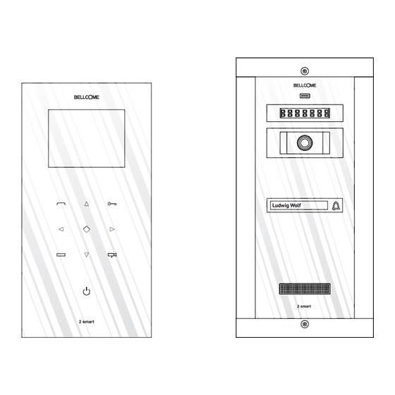
INHALT DES SETS Ludwig Wolf POWER SUPPLY - 2 smart (PS2.VDN.ENW) CAUTION! CAUTION! DO NOT REMOVE DO NOT REMOVE INPUT: ~230V ± 10% / 50 Hz / 0,4 A THE SAFETY LID! THE SAFETY LID! OUTPUT: 28V ± 10% / 1,2 A...
Tastatur TOUCH, ständig beleuchtet Die Anzeige des Namen der Bewohner Platz für die Namensanzeige mit Hintergrundbeleuchtung Befehl eines Relaiskontakt Elektromagnetisches Schloß Maximale Schaltstrom 1 A (DC oder AC) Befehl eines Hilfs Automatisierung Relaiskontakt (DC oder AC) Maximale Schaltstrom 1 A Aluprofil lackiert;...
2.3 Technische Eigenschaften der Stromversorgungseinheit Betriebsspannungen 230V±10%/50Hz Ausgangsspannung/ 28V±10% / 1.2 A Ausgangsleistung ABS mit Brandschutz Gehäuse - auf Schiene DIN: TH 35 x 15 oder 35 x 7,5 gemäß DIN46277-3, EN50022, IEC60715 Montage - Aufputz: mit Schrauben A3,5 x 32 und Dübel ø 6 mm Schutzklasse (IP) IP31 Betriebstemperaturbereich...
INSTALLATION 4.1 Empfohlene Kabel Außeneinheit Stromversorgungseinheit Die maximal erreichbare Distanz zwischen der Außeneinheit und der Stromversorgung hängt von der Art des verwendeten Kabels ab, z.B.: Litzenkabel (parallel) 2x075 mm bis zu 50m - Twisted Kabel 2x0.75mm bis zu 60m - Twisted Kabel 2x1 mm bis zu 80m Für Distanzen weiter als 80 Meter kontaktieren Sie bitte den Hersteller für weitere Informationen.
des Schaltschrankes und dem Erdungsleiter der Stromversorgungseinheit hergestellt werden. WICHTIG! Vor dem Einschalten der Netzsicherungen für die Stromversorgungseinheit, è überprüfen Sie die Richtigkeit der Anschlüsse. Prüfen sie diese visuell und auch mit Hilfe eines Ohmmeters. WICHTIG! Montieren sie unbedingt wieder die Abdeckungen der Anschlüsse an der è...
Unterputzmontage Position der Löcher für die Montage 1 3,0 60,0 Mounting Bohrlöcher depth für die = 2 cm Montage A3,5 × 35(32) Screw (4 pcs.) Kabeldurchführung ≈20 cm Cable lenght (from the wall) Türsprechkabel Es ist notwendig, im Voraus, ein Loch in der Wand zu machen: Breite = 103mm, Vorderansicht Höhe= 220mm, Tiefe = 20mm.
Antidiebstahl Schutz Torx Schraube Die Torx Schraube muß fest angezogen sein. Andernfalls, wenn das System eingeschalten ist, ertönt durch die Außeneinheit ein dauerhaftes Alarmsignal. Dies ist eine Warnfunktion und dient der Diesbtahlsicherung der Außeneinheit. Individualisierung mit den Bewohnernamen Die Kunststoffhalterung aus dem Die Kunststoffhalterung aus dem Kleben Sie einen Aufkleber mit dem Namen, zugeschnitten, auf den weißen Tastaturmodul wird nochmals...
5.1 Parallelschaltung von einer zusätzlicher Inneneinheit (optional) Außeneinheit Zusätzliche 230 V AC Haupt Inneneinheit Inneneinheit 1 2 3 4 5 6 1 2 3 4 5 6 Zu der Außen- einheit Stromversorgungseinheit Zu der Inneneinheit 5.2 Der Einbau des elektromagnetischen Schlosses (optional) Gleichstrom (DC) Wechselstrom (AC) Außeneinheit...
DIE INBETRIEBNAHME DER ANLAGE 6.1 Beschreibung der Stromversorgungseinheit Die Stromversorgungseinheit enthält: Schutzabdeckungen für Anschlüsse LED- Grün = POWER SUPPLY - 2 smart (PS2.VDN.ENW) CAUTION! CAUTION! DO NOT REMOVE DO NOT REMOVE Spannung vorhanden INPUT: ~230V ± 10% / 50 Hz / 0,4 A...
Seite 13
Stellen Sie sicher, dass Sie die Torx-Schraube des Außeneinheit ist gut aufgeschraubt, um Ÿ zu verhindern dem Einschalten der Anti-Diebstahl-Alarm. Überprüfen Sie die Betriebsspannung von den Leitern der Stromversorgungseinheit mit den unten angegeben Werte (verwenden Sie dafür einen Spannungsmesser für Gleichstrom). Die bei den Leitern der Stromversorgungseinheit gemessenen Spannunge n: 28V 10% ±...
Seite 14
Ein zusätzlicher Stromversorgungseinheit: Beide Inneneinheiten Für den zusätzlichen Inneneinheit ist mit der die LED ist GRÜN haben die Addresse 1. Inneneinheit wird die Anlage angeschlossen. Ausseneinheit: Addresse 2 eingestellt, d.h. Die Anlage funktioniert; Der Schlüssel und Name des vom Einstellungen-Menü einer der Inneneinheiten Bewohners haben eine (ch.
Seite 15
S1. Einstieg in das HAUPTMENÜ 1. Berühren Sie die MENÜ taste im Stand-by Modus. Datum und Uhrzeit leuchten auf. Nehmen Sie keine Einstellungen vor schaltet sich das Menü automatisch nach 3 Minuten ab. 2. Betätigen Sie erneut die MENÜ Taste .
Seite 16
S4. Slave address (Optional) Wählen Sie Erweiterte EInstellungen (Advanced set...). setup Slave Addr Set 1. Die Slave Adresseinstellung konfiguriert den Master und Slave User Guard Unit Set Code. Diese Parameter kommen zum Tragen wenn Sie ein zusätzliches Date/Time Set... Terminal zum Set erworben haben. Die Installation der Zusatzeinheit Other Settings...
Seite 17
S7. Display und Lautstärken Einstellungen Während einer Kommunikation drücken Sie die MENÜTASTE . Das ADJUSTMENTS Menü wird angezeigt. Benützen Sie die Tasten um zu wählen was eingestellt werden soll. Danach können Sie die Einstellungen mit den Tasten verändern. user 1. Einstellung Scene Mode Selection. Insgesamt können Sie zwischen 4 Scene Slave Addr Set 5...
Brand, Erdbeben, Einstellungen, die vom dafür nicht zugelassenen Personal ausgeführt wurden, wenn die Bestandteile der Anlage bei Renovierungsarbeiten nicht geschützt werden. Die BELLCOME Anlagen für Ein- und Mehrfamilienhäuser sind gemäß den gültigen EU-Vorschriften hergestellt und sind gemäß dem EG-Beschilderungsverfahren beschildert. AUTORISIERTER REPRÄSENTANT der ELECTRA S.R.L.
Seite 19
USER MANUAL KIT VIDEO DOOR PHONE 2 smart 1 family Ludwig Wolf Call from the Outdoor panel keys Possibility to see on the Terminal's display the person calling Duplex hands-free audio communication Opening command of the access gate/door from the indoor Terminal Video and audio monitoring of the entrance of the property, by the inhabitant Optional auxiliary command: auto-access, garage door, etc.
KIT COMPONENTS Ludwig Wolf Outdoor panel Indoor Terminal Power supply unit 1 pc. 1 pc. 1 pc. 237 × 122 × 25 mm 294 × 144 × 53 mm 130 × 141 × 73 mm TECHNICAL FEATURES OF THE SYSTEM Audio communication Duplex Data communication...
Seite 21
Keyboard TOUCH type, permanently backlit Display of the inhabitant's name Backlit name space Command of an Relay contact electromagnetic lock (DC or AC) Maximum switched current 1 A Command of an Relay contact auxiliary automation (DC or AC) Maximum switched current 1 A Aluminum profile painted in electrostatic field;...
Seite 22
2.3 Technical features of the Power supply unit Supply tension 230V±10%/50Hz Output voltage/ power capability 28V±10% / 1.2 A Fireproof ABS Case -On DIN rail: TH 35 x 15 or 35 x 7,5 in compliance with DIN46277-3, EN50022, IEC60715 Mounting -Surface: with A3,5 x 32 plastic screws and ø...
INSTALLATION 4.1 Recommended cables Outdoor panel Power supply unit Using different cables between the Outdoor panel and the Power supply unit, the following distances can be reached: - Pair Cable (parallel) 2 x 0.75 mm² for distances up to 50 m; - Twisted Cable 2 x 0.75 mm²...
(230V/50Hz). DANGER OF ELECTRIC SHOCK and of the door phone system's destruction. 4.3 Installation of the Power supply unit DIN rail mounting Wall mounting POWER SUPPLY - 2 smart (PS2.VDN.ENW) POWER SUPPLY - 2 smart (PS2.VDN.ENW) INPUT: ~230V ± 10% / 50 Hz / 0,4 A OUTPUT: 28V ±...
Seite 25
Flush mounting Position of necessary mounting holes 1 3,0 60,0 Mounting fixing depth screw = 2 cm hole A3,5 × 35(32) Screw (4 pcs.) cable hole ≈20 cm Cable lenght (from the wall) Door phone cable Frontal view It is necessary to make, in advance, a hole in the wall of W = 103mm, L= 220mm, of the back lid D = 20mm.
Antitheft protection Torx Screw The Torx screw must be completely screwed. Otherwise, when the system is powered, the Panel emits a permanent acoustic signal. This warning function is useful if an unauthorized person tries to open the Outdoor panel. The alarm turns on immediately after one starts to unscrew the Torx. Customization of name display Insert the pad back into the Remove the plastic pad from the...
Seite 27
5.1 Parallel connection of an additional Terminal (optional) Outdoor panel Main Additional 230 V AC Terminal Terminal 1 2 3 4 5 6 1 2 3 4 5 6 to the Outdoor panel Power supply to the Terminal 5.2 Installation of the electromagnetic lock (optional) Direct current (DC) Alternative current (AC) Outdoor panel...
COMMISIONING OF THE SYSTEM 6.1 Description of the Power supply unit The Power supply unit includes: Protection lid for connections LED - GREEN signaling POWER SUPPLY - 2 smart (PS2.VDN.ENW) = presence of tension CAUTION! CAUTION! DO NOT REMOVE DO NOT REMOVE INPUT: ~230V ±...
Make sure that the Torx screw is completely fastened to prevent the turning on of the anti- Ÿ theft alarm. Check the existence of the supply tensions with the values mentioned below, at the terminals of the Power supply unit (use a drive current voltmeter). Tensions measured at the terminals of the Power supply unit : 28V 10% ±...
An additional Both terminals have Set up address 2 for the Power supply: Terminal is mounted address 1. additional terminal, from GREEN LED the SETTINGS menu (ch. in the system. Outdoor panel: The system is 7.2 Use of the video The key and the name of the functioning;...
Seite 31
S1. How to enter the MAIN MENU Page 1. Touch the MENU key in stand-by mode, the Date/Time page will be showed. (The Date/Time page will turn off in 3 minutes if there is no operation.) 2. Touch the MENU key again .
Seite 32
S5. Restore to default Select Advanced set... setup Slave Addr Set Select the Information... item, this item will show information about Guard Unit Set the product: Hardware and software version, voltage information, Date/Time Set... manufacturing code. Other Settings... To set all the parameters of the terminal to initial values, select Information...
Seite 33
CALL , COMMUNICATION and ACCESS Call duration: maximum 40 s When a call is made from the Outdoor panel the four main keys light up. ANSWER THE CALL Communication duration: maximum 90 s The LED of the key blinks and the display shows the image sent by the video camera of the Outdoor panel.
MAINTENANCE The Outdoor panels must be kept away from corrosive substances, lime or mechanical shocks. The Terminals must be kept away from water, or any other liquids, mechanical shocks, fumes, dusts etc. The components of the system can be cleaned with a piece of soft, cotton cloth. WARRANTY A three year warranty is granted, from the purchase date, on the basis of the proof of purchase and if the system was used according to the technical manual.
MANUEL DE L'UTILISATEUR KIT VIDÉOINTERPHONE 2 smart 1 famille Ludwig Wolf Appel de la touche du panneau extérieur Afficher sur le terminal intérieur l'image de la personne qui est dans l'entrée Communication audio en duplex intégral mains-libres Ouverture du portillon / de la porte d'accès du terminal intérieur Surveillance audio et vidéo de l'entrée par le locataire...
COMPOSANTS DU KIT Ludwig Wolf Panneau extérieur Terminal Source d’ a limentation 1 pc. 1 pc. 1 pc. 237 × 122 × 25 mm 294 × 144 × 53 mm 130 × 141 × 73 mm CARACTÉRISTIQUES TECHNIQUES DE L'INSTALLATION Communication audio Duplex Data communication...
Seite 37
Clavier Type TOUCH, éclairé de façon permanente Affichage du nom du locataire Espace pour les noms avec rétro-éclairage Commande d'un Contact de relais serrure électromagnétique Courant commuté maximal 1 A (c.a. ou c.c.) Commande d'un Contact de relais automatisation auxiliaire Courant commuté...
2.3 Caractéristiques techniques de la source d’alimentation 230V±10%/50Hz Tensions d'alimentation Tension de sortie / 28V±10% / 1.2 A capacité en courant ABS ignifugé Carcasse - Sur rail DIN: TH 35 x 15 ou 35 x 7,5 selon DIN46277-3, EN50022, IEC60715 Montage - En surface: avec vises A3,5 x 32 et goujons ø...
Seite 39
INSTALLATION 4.1 Câbles recommandés Panneau extérieur Source d'alimentation Les distances maximales entre le Panneau extérieur et la Source d'alimentation sont obtenus en fonction du type de câble utilisé. - Câble 2 x 0.75 mm² pour les distances jusqu'à 50 m ; - Câble torsadé...
Seite 40
4.3 Installation de la source de courant Montage sur mur Montage sur Rail DIN POWER SUPPLY - 2 smart (PS2.VDN.ENW) POWER SUPPLY - 2 smart (PS2.VDN.ENW) INPUT: ~230V ± 10% / 50 Hz / 0,4 A INPUT: ~230V ±...
Seite 41
La position des trous de montage Montage encastré 1 3,0 60,0 Profondeur trou Trou de montage = 2 cm fixation Vis A3,5 × 35(32) (4 pc.) Trou de passage de câble ≈20 cm longueur du câble Câble vidéo (à partir de mur) interphone Il est nécessaire la réalisation en préalable d'un trou dans le mur de: Vue frontale...
Seite 42
Protection antivol Torx La vis Torx doit être complètement vissée. Autrement, quand le système est sous tension, le panneau émet un signal acoustique permanent. Cette fonction d'avertissement est utile si une personne non autorisée essaye d'ouvrir le panneau extérieur. L'alarme se déclenche immédiatement après on commence à...
Seite 43
5.1 Connexion d’un terminal additionnel en parallèle (en option) Panneau extérieur Terminal Terminal 230 V c.a. principal additionel 1 2 3 4 5 6 1 2 3 4 5 6 Panneau extérieur Source d’alimentation au Terminal 5.2 Installation d’un serrure électromagnétique (en option) Courant alternatif (CA) Courant continu (CC) Panneau extérieur...
Seite 44
6.1 La description de la source d’alimentation La source d’alimentation Couvercle de protection comprend: connexions LED – signalisation VERT : POWER SUPPLY - 2 smart (PS2.VDN.ENW) CAUTION! CAUTION! DO NOT REMOVE DO NOT REMOVE INPUT: ~230V ± 10% / 50 Hz / 0,4 A...
Assurez-vous que la vis Torx du panneau extérieur est complètement vissé à empêcher la Ÿ mise sous alarme anti-vol. Vérifier la présence des tensions d'alimentation avec les valeurs indiquées ci-dessous, aux bornes de la source d’alimentation (à l'aide d'un voltmètre de courant continu CC). Tensions mesurées aux bornes de la Source d'alimentation: 28V±10% Ÿ...
Seite 46
Un terminal La source d'alimentation: additionnel est L'adresse 2 dans le menu de LED- allumé VERDE installé en réglages (pct. …) est réglé Les deux terminaux ont Panneau extérieur: l'installation. pour le terminal additionnel l'adresse 1 La touche et le nom du L'installation (chap.
Seite 47
S1. Comment accéder au MENU PRINCIPAL 1. Appuyer sur la touche Menu - la page avec la Date / l'Heure apparaîtra. (La page Date / Heure se ferme automatiquement après 3 minutes sans autre commande) 2. Appuyer sur la touche Menu de nouveau - la page avec le MENU PRINCIPAL apparaîtra.
Seite 48
S5. Retour aux réglages de base Sélectionner Advanced set... setup Slave Addr Set Sélectionner Information... Les informations sur le produit seront Guard Unit Set affichées à l'écran: la version des logicielles et matérielles, la tension, le Date/Time Set... code du fabricant. Other Settings...
Seite 49
APPELLATION, CONVERSATION ET ACCÈS Durée de l'appellation: jusqu'à 40 s Lorsque le terminal est appelé dans le panneau extérieur, les touches s'allument. ANSWER THE CALL Durée de la conversation: jusqu'à 90 s Le LED de la touche clignote et l'écran affiche l'image prise par la caméra vidéo du panneau Appellation extérieur.
Les installations BELLCOME pour bâtiments de type villa sont effectués conformément aux normes de l'UE et portent le marquage selon CE.
Seite 51
IL MANUALE DELL'UTENTE KIT VIDEO-CITOFONO 2 smart 1 famiglia Ludwig Wolf Chiamata dal tasto del pannello esterno La visualizzazione sul terminale interno dell'immagine della persona che è all'ingresso Comunicazione audio duplex vivavoce Apertura del cancello/ porta di accesso dal terminale interno...
COMPOSIZIONE DEL KIT Ludwig Wolf Pannello esterno – 1 pezzo Terminale – 1 pezzo Fonte di alimentazione - 1 pezzo 130 × 141 × 73 mm 237 × 122 × 25 mm 294 × 144 × 53 mm CARATTERISTICHE TECNICHE DELL'IMPIANTO Comunicazione audio Duplex Comunicazione dati...
Seite 53
Tastiera Tipo TOUCH, illuminata permanentemente Visualizzazione del nome del Spazio per nomi con retroilluminazione locatario Comando di una Contatto relè serratura elettromagnetica (c.c. o c.a.) Massima corrente commutata 1 A Comando di una automazione Contatto relè ausiliaria (c.c. o c.a.) Massima corrente commutata 1 A Profilo in alluminio verniciato in campo elettrostatico;...
Seite 54
2.3 Caratteristiche tecniche della fonte di alimentazione Tensioni d'alimentazione 230V±10%/50Hz La tensione di uscita / 28V±10% / 1.2 A capabilità di corrente ABS ignifugo Carcassa -Sulla rotaia DIN: TH 35 x 15 o 35 x 7,5 in conformità ai DIN 46277-3, EN50022, IEC60715 Montaggio - Apparentemente: con vite A3,5 x 32 e taselli ø...
INSTALLAZIONE 4.1 Cavi raccomandati Pannello esterno Fonte di alimentazione Le distanze massime tra il Pannello esterno e la Fonte di alimentazione sono ottenute in funzione del tipo di cavo utilizzato. - Cavo 2 x 0.75 mm² per le distanze non superiori a 50 m; - Cavo twistato 2 x 0.75 mm²...
Seite 56
(230V/50Hz). PERICOLO DI SCOSSA ELETTRICA e di distruzione dell'impianto di video citofono. 4.3 L'installazione della fonte di alimentazione Montaggio sulla rotaia DIN Montaggio su muro POWER SUPPLY - 2 smart (PS2.VDN.ENW) POWER SUPPLY - 2 smart (PS2.VDN.ENW) INPUT: ~230V ± 10% / 50 Hz / 0,4 A OUTPUT: 28V ±...
Seite 57
Montaggio sepolto La posizione degli incavi di montaggio 1 3,0 60,0 Profondità Incavo incavo vite montaggio = 2 cm fissaggio Vite A3,5 × 35(32) (4 pezzi) Incavo passaggio cavo ≈20 cm Lunghezza cavo (dal muro) Cavo citofono Vista frontale E necessario realizzare, prima di tutto, un incavo nel muro di: coperchio I = 103 mm, L = 220 mm, A = 20 mm.
Protezione antifurto Vite Torx La vite Torx deve essere completamente avvitato. Altrimenti, quando il sistema è alimentato, il pannello emette un segnale acustico permanente. Questa funzione di avviso è utile se una persona non autorizzata tenta di aprire il pannello esterno. L'allarme si accende subito dopo si comincia a svitare il Torx.
Seite 59
5.1 Collegamento in parallelo di un terminale aggiuntivo (opzionale) Pannello esterno Terminale Terminale 230 V c.a. principale aggiuntivo 1 2 3 4 5 6 1 2 3 4 5 6 Pannello esterno Fonte di alimentazione Terminale 5.2 L'installazione della serratura elettromagnetica (opzionale) Corrente continua (c.c.) Corrente alternata (c.a.) Pannello esterno...
Seite 60
LA MESSA IN FUNZIONE DELL'IMPIANTO 6.1 Descrizione della fonte di alimentazione La fonte di alimentazione include: Coperchio protezione connessioni LED - Segnalazione VERDE POWER SUPPLY - 2 smart (PS2.VDN.ENW) = Presenza di tensione CAUTION! CAUTION! DO NOT REMOVE DO NOT REMOVE INPUT: ~230V ±...
Seite 61
Assicurarsi che la vite Torx del pannello esterno è completamente avvitato per prevenire Ÿ accendere l'allarme antifurto. Verificate la presenza delle tensioni d'alimentazione con i valori specificati più giù, ai morsetti della fonte di alimentazione (utilizzate un voltmetro di corrente continua). Le tensioni misurate ai morsetti della Fonte di alimentazione: 28V 10% ±...
Seite 62
La fonte di alimentazione: Viene montato anche un I due terminali hanno Si fissa per il terminale terminale addizionale LED – acceso VERDE l'indirizzo 1. addizionale l'indirizzo 2 Il pannello esterno: dal MENU nell'impianto. il tasto e il nome del L'installazione funziona;...
Seite 63
S1. Come aprire il MENU PRINCIPALE 1. Toccate il tasto Menu – ci appare la pagina Data / Ora. (La pagina Data / Ora si chiude automaticamente fra 3 minuti in assenza di un altro comando) 2. Toccate il tasto Menu di nuovo –...
Seite 64
S5. Ritorno alle impostazioni di base Selezionate Advanced set … setup Slave Addr Set Selezionate Information … Sullo schermo saranno indicate le Guard Unit Set informazioni sul prodotto: la versione hardware e software, il voltaggio, Date/Time Set... il codice di produttore. Other Settings...
Seite 65
CHIAMATA, CONVERSAZIONE E ACCESSO Durata della chiamata: non superiore a 40 s Quando il terminale viene chiamato dal pannello esterno i tasti si accendono. RISPONDE ALLA CHIAMATA Durata della conversazione: non superiore a 90 s Il LED del tasto lampeggia e il display mostra l'immagine ripresa dalla camera video del pannello esterno.
Gli impianti BELLCOME per palazzi tipo villa sono realizzati in conformità agli standard UE e hanno il marchio di conformità CE. RAPPRESENTANTE AUTORIZZATO ELECTRA S.R.L.
GEBRUIKERSHANDLEIDING KIT VIDEOINTERFON 2 smart 1 gezin Ludwig Wolf Oproep van de knop van het externe paneel Kijk op de interne terminal van het beeld van de persoon die zich bij de ingang bevindt Full- duplex audio-communicatie hands-free Mogelijkheid van het openen van de toegangspoort/deur van de inwendige terminal...
Seite 68
KIT SAMENSTELLING Ludwig Wolf Uitwendig paneel – 1 stuk Terminal - 1 stuk Voedingseenheid - 1 stuk 294 × 144 × 53 mm 237 × 122 × 25 mm 130 × 141 × 73 mm TECHNISCHE KENMERKEN VAN DE INSTALLATIE Audio-communicatie Duplex Gegevens communicatie...
Seite 69
TOUCH type, permanent verlicht Toetsenbord Weergave naam bewoner Ruimte voor namen met achtergrondverlichting Opdracht van een Relaiscontact elektromagnetische slot (DC of AC) Maximale schakelstroom 1 A Opdracht van een aanvullende Relaiscontact automatisering (DC of AC) Maximale schakelstroom 1 A Aluminium profiel geverfd in elektrostatische veld; Huisvesting Veiligheidsglas scherm, dikte 8mm Montage...
Seite 70
Technische kenmerken van de voedingseenheid Spanningen 230V±10%/50Hz Uitgangsspanning / 28V±10% / 1.2 A Stroom toevoer in de installatie Brandvrije ABS Huisvesting - Op DIN spoor: TH 35 x 15 of 35 x 7,5 volgens DIN46277-3, EN50022, IEC60715 Montage - Schijnbaar: met schroeven A3,5 x 32 en paspen ø...
Seite 71
INSTALLEREN 4.1 Aanbevolen kabels Uitwendig paneel Voedingseenheid De maximale afstanden tussen het Uitwendig Paneel en de Voedingseenheit worden bereikt door gebruikmaking van verschillende types kabels. - kabel 2 x 0,75 mm2 voor afstanden van ten hoogste 50 m; - twisted pair-kabel 2 x 0.75 mm² voor afstanden van ten hoogste 60 m; - twisted pair-kabel 2 x 1 mm²...
Seite 72
ELEKTRISCHE SCHOK en vernietiging van het video-intercom systeem. 4.3 Installeren van de voedingseenheid Montage op Rail DIN Montage aan de wand POWER SUPPLY - 2 smart (PS2.VDN.ENW) POWER SUPPLY - 2 smart (PS2.VDN.ENW) INPUT: ~230V ± 10% / 50 Hz / 0,4 A OUTPUT: 28V ±...
Seite 73
Ingegraven montage Plaats van de montagegaten 1 3,0 60,0 Diepte van de gat voor montagegat = 2 cm bevestigingsschroef Schroef A3,5 × 35(32) (4 stuks) waardoor de kabel loopt ≈20 cm Kabellengte (vanaf de wand) Videointerfonkabel Eerst dient u een gat te boren in de muur van: Voorzijde Breedte = 103 mm, Lengte = 220 mm, Diepte = 20 mm achterdeksel...
Seite 74
Diefstalbeveiliging Schroef Torx De Torx-schroef moet helemaal ingeschroefd. Anders, wanneer het systeem wordt ingeschakeld, het paneel geeft continu geluidssignaal. Deze waarschuwing functie is handig als een onbevoegde persoon probeert om het paneel buiten te openen. Het alarm wordt ingeschakeld onmiddellijk na men begint om schroef de Torx. Personalisering met naam van de bewoner Plak een sticker met de naam van witte ruimte toegewezen, op maat Men verwijdert het plastic steun...
Seite 75
5.1 Toegevoegde terminals in parallel (optioneel) Paneel Hoofd Aanvulende 230 V wisselstroom Terminal Terminal 1 2 3 4 5 6 1 2 3 4 5 6 naar de Paneel Voedingseenheid naar de Terminal 5.2 Installeren van het elektromagnetische slot (optioneel) Wisselstroom Gelijkstroom Paneel...
Seite 76
IN WERKING STELLEN VAN DE INSTALLATIE 6.1 Beschrijving van de voedingseenheid De voedingseenheid bestaat uit: Beschermkap verbindingen LED - POWER SUPPLY - 2 smart (PS2.VDN.ENW) CAUTION! CAUTION! DO NOT REMOVE DO NOT REMOVE Signaalled GROEN = INPUT: ~230V ±...
Seite 77
Zorg ervoor dat de Torx-schroef van de uitwendige paneel wordt volledig geschroefd om te Ÿ voorkomen inschakelen van de anti-diefstal alarm. Controleer de aanwezigheid van de voedingsspanningen met de waarden hieronder beschreven, op de klemmen van de voedingseenheid (gebruik een voltmeter voor gelijkstroom). Spanningen gemeten op de klemmen van het Voedingseeheid: 28V 10% ±...
Seite 78
Er bestaat een Beide terminals hebben Voor de aanvullende Voedingseenheid: aanvullende terminal het adres 1 terminal dient u het adres Led - groen verlicht 2 in te stellen in de in de installatie. Uitvendige paneel De installatie werkt; Instellingen-menu (punt De toets en de naam van de een van de terminals 7.2 Gebruik van de video...
Seite 79
S1. Aanwijzingen om naar het HOOFDMENU te gaan 1. Raak de Menu-toets aan! Op het scherm verschijnt een melding: Datum / Uur. (Deze ʹDatum / Uurʹ - melding verdwijnt automatisch na drie minuten als u geen andere opdracht kiest) 2. Raak de Menu-toets opnieuw aan! Op het scherm verschijnt het HOOFDMENU.
Seite 80
Om alle parameters van de terminal in de oorspronkelijke staat terug te brengen, selecteer Restore to default, dan raak de Menu-toets aan. (De keuze Restore to default veroorzaakt geen wijziging van datum en uur. ) Slave Addr Set Selecteer Exit en raak de Menu-toets om terug te gaan naar het Guard Unit Set HOOFDMENU.
Seite 81
OPROEPEN, SPREKEN EN TOEGANG VERLENEN De duur van de oproep: maximaal 40 s Wanneer de terminal opgeroepen wordt vanuit het uitwendige paneel, worden de toetsen verlicht. EEN OPROEP BEANTWOORDEN De duur van het gesprek: maximaal 90 s De led van de toets knippert en op de display verschijnt het beeld dat ontvangen Oproep wordt door de videocamera van het externe paneel.
Seite 82
De BELLCOME-installaties voor gebouwen van het type villa zijn uitgevoerd in overeenstemming met de EU-voorwaarden en dragen het keurmerk CE. GEMACHTIGDE van ELECTRA S.R.L.
INSTRUKCJA UŻYTKOWNIKA ZESTAW WIDEODOMOFONU advanced 1 rodziny Ludwig Wolf Przycisk wywołania na panelu zewnętrznym Podgląd w module wewnętrznym osoby znajdującej się przy wejściu Prowadzenie rozmowy full-duplex hands-free Otwarcie bramy/drzwi wejściowych z modułu wewnętrznego Monitorowanie audio i wideo wejścia przez domownika Opcjonalne zamówienie wyposażenia dodatkowego: automatyczne bramy, drzwi garażowe itp..
ZAWARTOŚĆ ZESTAWU Ludwig Wolf Panel zewnętrzny - 1 szt. Moduł - 1 szt. Jednostka główna - 1 szt. 294 × 144 × 53 mm 237 × 122 × 25 mm 130 × 141 × 73 mm CHARAKTERYSTYKA TECHNICZNA INSTALACJI Transmisja audio Dwukierunkowy Transmisja danych Cyfrowa...
Seite 85
Klawiatura Typ TOUCH, trwale podświetlana Wyświetlanie nazwiska domownika Podwietlane miejsce na nazwisko Dowództwo zamek Styk przekaźnika elektromagnetyczny (p.p. lub p.s.) Maksymalny prąd przełączalny 1 A Dowództwo automatyzacja Styk przekaźnika pomocniczy (p.p. lub p.s.) Maksymalny prąd przełączalny 1 A Profil aluminiowy malowany elektrostatyczne; Obudowa Ekran ze szkła bezpiecznego, o grubości 8 mm Wkopanie...
Seite 86
2.3 Charakterystyka techniczna źródła zasilania Napięcia zasilania 230V±10%/50Hz Napięcie wyjściowe / 28V±10% / 1.2 A zdolność prądowa ABS ogniotrwały Obudowa - Na szynie DIN: TH 35 x 15 lub 35 x 7,5 zgodnie z DIN46277-3, EN50022, IEC60715 Instalacja - Widocznie: za pomocą śrub A3,5 x 32 i kołków ø...
Seite 87
INSTALACJA 4.1 Zalecane przewody Panel zewnętrzny Źródło zasilania Maksymalna odległość pomiędzy Panelem zewnętrznym i Źródłem zasilania uzyskana jest w zależności od rodzaju zastosowanego przewodu. - Przewód 2 x 0.75 mm² dla maksymalnych odległości wynoszących 50 m; - Skrętka 2 x 0.75 mm² dla odległości do 60 m; - Skrętka 2 x 1 mm²...
Seite 88
(230V/50Hz). RYZYKO PORAŻENIA PRĄDEM ELEKTRYCZNYM i uszkodzenia instalacji wideodomofonu. 4.3 Instalacja żródła do zasilania Zainstalowanie na Szynie DIN Zainstalowanie na ścianie POWER SUPPLY - 2 smart (PS2.VDN.ENW) POWER SUPPLY - 2 smart (PS2.VDN.ENW) INPUT: ~230V ± 10% / 50 Hz / 0,4 A OUTPUT: 28V ±...
Seite 89
Zainstalowanie wkopanie Pozycja otworów montażowych 1 3,0 60,0 Głębokość Otwór otworu do na śrubę montażu = 2 cm mocowania Śruba A3,5 × 35(32) (4 szt.) Otwór na przewód ≈20 cm Długość przewodu (od ściany) Przewód domofonu Widok Konieczne jest dokonanie otworu w ścianie o wymiarze: l = 103mm, L= 220mm, z przodu A = 20mm.
Ochronie przed kradzieżą Śruba Torx Śruba Torx musi być całkowicie pijany. W przeciwnym wypadku, gdy system jest zasilany, Panel emituje stały sygnał dźwiękowy. Funkcja ta jest przydatna, jeśli ostrzeżenie nieupoważniona osoba próbuje otworzyć panel odkryty. Alarm włącza się natychmiast po jednym zaczyna odkręcić...
Seite 91
Dodatkowe moduły równoległe (opcjonalnie) Panel Moduł Moduł 230 V p.p. główny dodatkowy 1 2 3 4 5 6 1 2 3 4 5 6 Panelu Źródło zasilania Modułu 5.2 Instalacja zamek elektromagnetyczny (opcjonalnie) Prąd stały (PS) Prąd przemienny (PP) Panel Panel Przewód Przewód...
6.1 Opis źródła zasilania Źródło zasilania obejmuje: Pokrywa zabezpieczająca połączenia Dioda LED – sygnał ZIELONY POWER SUPPLY - 2 smart (PS2.VDN.ENW) CAUTION! CAUTION! DO NOT REMOVE DO NOT REMOVE INPUT: ~230V ± 10% / 50 Hz / 0,4 A THE SAFETY LID!
Seite 93
Upewnij się, że śruby Torx panelu zewnętrznego jest całkowicie przykręcony zapobiec Ÿ włączania autoalarmu. Należy sprawdzić obecność napięcia zasilania z wartościami podanymi poniżej, do zacisków źródła zasilania ( za pomocą woltomierza prądu ciągłego). Mierzone napięcia w zaciskach Zródłą zasilania: 28V±10% Ÿ...
Seite 94
Zainstalowany jest i Oba terminale mają Należy ustawić dla Zródło zasilania: dodatkowy adres 1. dodatkowego terminalu Moduł Dioda LED- ZIELONA adres 2 w MENU jednostce. Panel zewnętrzny: Instalacja USTAWIEŃ ( rozdziałem Przycisk oraz nazwisko funkcjonuje; jeden z 7.2 Użytkowanie modułu domownika są...
Seite 95
S1. Sposób dostępu do GŁÓWNEGO MENU 1. Naciśnij przycisk Menu – pojawi sie strona z Data/Godzina. (strona Data/Godzina zostanie zamknieta automatycznie w 3 minuty bez żadnego innego polecenia). 2. Naciśnij poniwnie przycisk Menu - pojawi sie strona z GŁÓWNE MENIU. 3.
Seite 96
przycisk Menu . (Operacja Restore to default nie zmieni ustawienia daty i godziny.) Slave Addr Set Wybierz polecenie zakończ Exit i naciśnij przycisk Menu , aby Guard Unit Set powrócić do GŁÓWNEGO MENU. Date/Time Set... Other Settings... S6. Ustawienie parametra blokowania Information...
Seite 97
DZWONIENIE, ROZMOWA I DOSTĘP Czas połązcenia : maksymalnie 40 s Jeżeli terminal jest włączonyod zewnętrzego panelu klawisze są w stanie świecenia. ODEBRANIE POŁĄCZENIA Czas rozmowy: maksymalnie 90 s Dioda LED przycisku pulsuje a wyśiwtlacz pokazuje obraz przekazany z kamery wideo panelu zewnetrznego.
Seite 98
żywiołowych, nieautoryzowanych interwencji w systemie, brak elementów ochrony systemu podczas wykonywania robót remontowych. Systemy BELLCOME dla budynków typu willa są wykonane zgodnie z normami EU i są opatrzone oznakowaniem zgodności CE. AUTORYZOWANY PRZEDSTAWICIEL ELECTRA S.R.L. ELECTRA Building Communications GmbH Parkring 10, Liebenberggasse 7 | 1010 Wien –...