Inhaltsverzeichnis
Werbung
Verfügbare Sprachen
Verfügbare Sprachen
BENUTZERHANDBUCH
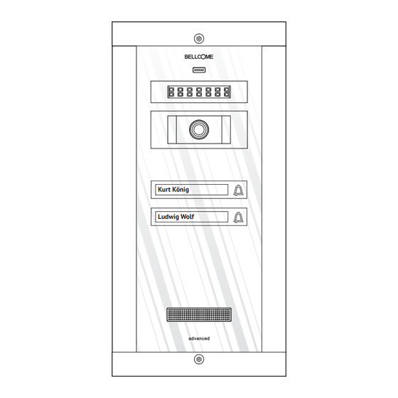
SET VIDEOTÜRSPRECHANLAGE advanced
2 Familien
Ruf tätigen mit Hilfe der Ruftaste der Außeneinheit
Ein Bild von der Person, die sich an der Eingangstür befindet, von der Inneneinheit
aus sehen
Full-duplex Freisprech Audiokommunikation
Das Zugangstor / die -Tür von der Inneneinheit aus öffnen
Die Audio- und Videoüberwachung des Eingangsbereiches
Optionaler Einbau von bis zu vier zusätzliche Videokameras
Optionaler Hilfsbefehl: Autotor, Garagentür usw.
Optional 1 VideoInneneinheit oder max. 3 parallel angeschlossene Audioinneneinheiten
Optional max. 3 parallel angeschlossene Außeneinheiten
UTP CAT 5e (AWG 24) Kabel erforderlich
Kurt König
Ludwig Wolf
DE
Werbung
Inhaltsverzeichnis

Verwandte Anleitungen für Bellcome SET VIDEOTÜRSPRECHANLAGE advanced


Inhaltszusammenfassung für Bellcome SET VIDEOTÜRSPRECHANLAGE advanced
- Seite 1 BENUTZERHANDBUCH SET VIDEOTÜRSPRECHANLAGE advanced 2 Familien Kurt König Ludwig Wolf Ruf tätigen mit Hilfe der Ruftaste der Außeneinheit Ein Bild von der Person, die sich an der Eingangstür befindet, von der Inneneinheit aus sehen Full-duplex Freisprech Audiokommunikation Das Zugangstor / die -Tür von der Inneneinheit aus öffnen Die Audio- und Videoüberwachung des Eingangsbereiches Optionaler Einbau von bis zu vier zusätzliche Videokameras Optionaler Hilfsbefehl: Autotor, Garagentür usw.
-
Seite 2: Inhalt Des Sets
1 INHALT DES SETS Stromversorgungseinheit Außeneinheit – 1 Stück Inneneinheit – 2 Stück Verbindungsbox – 1 Stück – 1 Stück 294 × 144 × 53 mm 212 × 96 × 30 mm 100 × 71 × 60 mm 130 × 141 × 73 mm 2 TECHNISCHE EIGENSCHAFTEN DER ANLAGE Audiokommunikation Full-duplex... -
Seite 3: Technische Eigenschaften Der Stromversorgungseinheit
2.2 Technische Eigenschaften der Inneneinheiten Betriebsspannung 12,0 ... 14,3 V Gleichstrom (stabilisiert) 3.5” LCD, TFT, Auflösung: 320 x RGB x 240; LCD Anzeige Sichtwinkel oben / unten / rechts / links: 40/60/60/60 TOUCH, 4 Tasten, beleuchtet, bei Betätigung der Tastatur Tastatur Die VOLUMEN-Taste leuchtet ständig ROT, wenn das Gerät ausgeschaltet ist... -
Seite 4: Blockdiagramm Der Anlage
Ausgang (Derivation) Gehäuse - auf Schiene DIN: TH 35 x 15 oder 35 x 7,5 gemäß DIN46277-3, EN50022, IEC60715 Montage - Aufputz: mit Schrauben und Dübel Schutzklasse (IP) IP31 Betriebstemperaturbereich 0° C ... + 45° C Transport- und - 33° C ... + 55° C Lagerungstemperaturen Masse 100 x 71 x 60 mm... -
Seite 5: Blockdiagramm Für Den Parallelen Anschluss Von Der Außeneinheiten (Optional)
3.1 Blockdiagramm für den Anschluss von vier Videokameras mit Videoverbindungsbox (optional) Außeneinheit Stromversorgungseinheit Zur Verbindungsbox Videoverbindungsbox 3.2 Blockdiagramm für den parallelen Anschluss von der Außeneinheiten (optional) Außeneinheit 2 Außeneinheit 3 Außeneinheit 4 Außeneinheit 1 Stromversorgungseinheit Stromversorgungseinheit Stromversorgungseinheit Stromversorgungseinheit Videoverbindungsbox Verbindungsbox INSTALLATION 4.1 Empfohlene Kabel Außeneinheit Stromversorgungseinheit... -
Seite 6: Stromversorgungseinheit Elektromagnetisches Schloss (Optional)
Stromversorgungseinheit Elektromagnetisches Schloss (Optional) Mehrfaserkabel, flexibel, (Cu) 2 oder 3 x 0,75 mm² für Längen von bis zu max. 50 m oder (Cu) 2 oder 3 x 1 mm² für Längen von bis zu max. 100 m. Stromversorgungseinheit 230 V Netz Wechselstrom. Mehradriges Kabel, flexibel, (Cu) 3x0,5 mm²... -
Seite 7: Der Einbau Der Stromversorgungseinheit
4.3 Der Einbau der Stromversorgungseinheit Einbau auf einer DIN Schiene Aufputz DIN Schiene Befestigungsklammern A3,5 × 32 Schraube (2 St.) Schutzdeckel (2 St.) B2,9 × 13 Schraube (4 St.) Vorderansicht Seitenansicht Hinteransicht Der Akku wird an die Leiter der Stromversorgungseinheit nach der Inbetriebnahme der Anlage angeschlossen. -
Seite 8: Der Einbau Der Inneneinheiten
4.5 Der Einbau der Inneneinheiten Bevor Sie anfangen... A3,5 × 35(32) Schraube Befestigungsteil (4 St.) – Führungsteil für Kabel 18 cm Die Inneneinheit wird auf einer Höfe von Die Kabellänge 155 cm (empfohlene Höhe) montiert. (von der Wand) Vorderansicht Seitenansicht Hinteransicht 4.6 Der Einbau der Außeneinheit Die Außeneinheit wird beim Grundstück- oder Hauseingang, auf die Halterung, die dem... - Seite 9 Bevor Sie anfangen... Der Gehäuserahmen Torx Die Außeneinheit muss bündig mit Schraube wird beim der Wand sein. Hauseingang auf die Halterung, die der Zugangstür am nächsten liegt, montiert . ≈20 cm Kabellänge Torx Schraube Türsprechanlagekabel für Diebstahlschutz Antidiebstahl Schutz Torx Schraube Die Torx Schraube muß...
-
Seite 10: Das Anschlussschemata
DAS ANSCHLUSSSCHEMATA 10/17... - Seite 11 5.1 Der Einbau des elektromagnetischen Schlosses (optional) Gleichstrom (DC) Wechselstrom (AC) Kabel 2 x 0.75 mm² Trafo 230 V AC 12 V LA/C Kabel Gleichstrom (DC) elektromagnetisches Schloss 2 x 0.75 mm² Stromversorgungseinheit Die Stromversorgungseinheit kann Strom von LA/C max.
-
Seite 12: Die Betriebs- Und Regelungsüberprüfung
Stellen Sie sicher, dass Sie die Torx-Schraube des Außeneinheit ist gut aufgeschraubt, um zu verhindern dem Einschalten der Anti-Diebstahl-Alarm. Schliessen Sie die Stromversorgungseinheit an das 230 V Wechselstrom Netz an, indem Sie die zwei 10 A Automatsicherungen, die auf dem Phasen- und Nulleiter eingebaut sind mit der Stromversorgungseinheits verbinden. - Seite 13 Die 10 A Sicherungen im Sicherungskasten und die 1 Stromversorgung: Keine Spannung Die Anlage läuft nicht und 1,6 A Sicherungen vom vom 230 V ( Stromversorgungseinheit Stromversorgungseingang Wechselstrom ohne Akku) werden überprüft. PROG: Netz. Überprüfen der Kabelverbindungen. Ursachen für den Stromversorgung: Kurzschluss in der Kurzschluss finden und...
-
Seite 14: Sicherheitseinweisungen Bei Der Verwendung
Die an den Vin / Während des Anrufes Vout und GNV Leitern und / oder der angeschlossene Stromversorgung: Diskussion kann man Suchen und beheben Drähte sind verdreht S1: grün horizontale oder Sie den Fehler. bis in der Nähe der S2: grün schräge, feste oder Leiter (bis zu 1 cm vor PROG:... -
Seite 15: Die Verwendung Der Video Inneneinheiten
7.2 Die Verwendung der Video Inneneinheiten STAND-BY Die Tastatur ist aus. Bei der ersten Berührung wird die Tastatur eingeschalten, die Inneneinheit kann die nächsten Befehle erhalten: AUDIO-, VIDEOÜBERWACHUNG + VIDEOKAMERAAUSWAHL Die Überwachungsdauer: 10 s Indem eine Taste berührt wird, können Sie das was im Eingangsbereich, d.h. vor Stand-by der Außeneinheit passiert, hören und sehen. -
Seite 16: Die Verwendung Der Außeneinheit
7.3 Die Verwendung der Außeneinheit STAND-BY Die Anruftaste und die Bewohnernamen sind ständig beleuchtet. Das rote Blicklicht der LED signalisiert die Videoüberwachung. ANRUFEN UND SPRECHEN Die Anrufzeit: max. 15 s (3 Anrufen) Die Diskussionszeit: max. 2 min Berühren Sie die Taste liegt der Mieter gesucht. -
Seite 17: Löschen Aller Tags
Brand, Erdbeben, Einstellungen, die vom dafür nicht zugelassenen Personal ausgeführt wurden, wenn die Bestandteile der Anlage bei Renovierungsarbeiten nicht geschützt werden. Die BELLCOME Anlagen für Ein- und Mehrfamilienhäuser sind gemäß den gültigen EU-Vorschriften hergestellt und sind gemäß dem EG-Beschilderungsverfahren beschildert. AUTORISIERTER REPRÄSENTANT der ELECTRA S.R.L. - Seite 18 USER MANUAL KIT VIDEO DOOR PHONE advanced 2 families Kurt König Ludwig Wolf Call from the Outdoor panel’s key Possibility to see on the Terminal's display the person calling Full duplex hands-free audio communication Command of the access gate/door opening from the indoor Terminal Video and audio monitoring of the entrance of the property, by the inhabitant Optional connection of up to 4 additional video cameras Optional auxiliary command: auto access, garage door, etc.
-
Seite 19: Kit Components
1 KIT COMPONENTS Indoor Terminal Supply control Video connection Outdoor panel – 1 pc. – 2 pcs. unit– 1 pc. box – 1 pc. 294 × 144 × 53 mm 212 × 96 × 30 mm 130 × 141 × 73 mm 2 TECHNICAL FEATURES OF THE SYSTEM Audio communication Full-duplex... - Seite 20 2.2 Technical features of the video Terminal Supply tension 12,0 ... 14,3 V DC (stabilized) 3.5” LCD, TFT, resolution: 320 x RGB x 240; Display Display Up/down/right/left visibility angle: 10/35/50/50 TOUCH type,4 keys Backlit on touch Keyboard Permanent RED signaling of the VOLUME key if the Terminal is turned off.
- Seite 21 Outputs (derivations) Case -On DIN rail: TH 35 x 15 or 35 x 7,5 in compliance with DIN46277-3, EN50022, IEC60715 Mounting -Surface: with plastic screws and pins IP31 Casing protection level (IP) Operating temperature range 0° C ... + 45° C Range of transport and storage - 33°...
-
Seite 22: Installation
3.1 Block diagram of the Video selection box connected with 4 additional video cameras (optional) Panel Supply control unit To the video connection box Video selection 3.2 Block diagram of the connection of additional Outdoor panels (optional) Panel 1 Panel 2 Panel 3 Panel 4 Supply control... -
Seite 23: Safety Instructions For Installation
Supply control unit Electromagnetic lock (optional) Flexible, multistrand cable, (Cu) 2 or 3 x 0,75 mm² for distances of maximum 50 m or (Cu) 2 or 3 x 1 mm² for distances of maximum 100 m. Supply control unit 230 V AC network Flexible, multistrand cable, (Cu) 3 x 0,75 mm²... -
Seite 24: Wall Mounting
4.3 Installation of the Supply control unit Wall mounting DIN rail mounting DIN rail Retainer A3,5 x 32 screw (2 pcs.) Protection lid (2 pcs.) B2,9 x 9,5 screw (4 pcs.) Frontal view Lateral view Back view The accumulator will be connected to the terminals of the Supply control unit, after the commissioning of the system. - Seite 25 4.5 Installation of the video Terminal Before starting... Cable retainers A3,5 x 32(35) screw – adapters (4 pcs.) The Terminal will be placed at the 18 cm Cable length 155cm height (recommended height) (from the wall) Frontal view Lateral view Back view 4.5 Installation of the Outdoor panel The Outdoor panel is installed at the entrance of the property or building, on the body closest...
- Seite 26 Before starting... The Outdoor panel is installed at the entrance to the building, on the body closest to the entrance door. Torx Screw for antitheft protection Door phone cable Antitheft protection Torx Screw The Torx screw must be completely screwed. Otherwise, when the system is powered, the panel emits a permanent acoustic signal. This warning function is useful if an unauthorized person tries to open the Outdoor panel.
-
Seite 27: Connection Diagram
CONNECTION DIAGRAM 10/17... -
Seite 28: Commisioning Of The System
(optional) 5.1 Installation of the electromagnetic lock Direct current (DC) Alternative current (AC) Cable 2 x 0.75 mm² Transformer 230 V AC 12 V LA/C Cable Direct current electromagnetic lock (DC) 2 x 0.75 mm² Supply control unit The Supply control unit can supply a current of LA/C ... -
Seite 29: Troubleshooting
Make sure that the Torx screw of the Outdoor panel is completely screwed to prevent turn ing on the anti-theft alarm. Connect the Supply control unit to the 230 V AC network, by connecting the two automatic 10A fuses, installed on phase and null. Optionally, connect the accumulator to the +ACC and –ACC terminals of the Supply control unit. - Seite 30 Check the 10A fuses from the electrical Control unit: The system does not Lack of panel and the 1,6A function tension from Fuse 1 from the Supply (Supply control unit the 230V AC control unit input. PROG: without accumulator) network Check the continuity of the supply cables.
-
Seite 31: User Safety Instructions
The wires connected During the call and/or to the Vin / Vout and communication, the Control unit: GNV terminals are not image on the Locate and remedy the S1: green twisted until close to Terminal's screen defect. S2: green the terminals (until presents horizontal or PROG: approx. - Seite 32 7.2 Use of the video Terminal STAND-BY The keyboard is not backlit. At the first touch, the keyboard is backlit and the Terminal may receive the following commands: AUDIO – VIDEO MONITORING +VIDEO CAMERA SELECTION Monitoring duration: 10 s By touching this key, you may see and listen to what goes on at the entrance, in Stand-by front of the Outdoor panel.
- Seite 33 7.3 Use of the Outdoor panel STAND-BY The keyboard of the Outdoor panel and the inhabitants’ list are permanently backlit. The intermittent RED led signals the presence of video monitoring. CALL AND COMMUNICATION Call duration: maximum 15 s (3 calls) Communication duration: maximum 2 min.
-
Seite 34: Maintenance
The BELLCOME video systems for residential buildings are produced in compliance with the EU standards and bear the CE conformity marking. AUTHORIZED REPRESENTATIVE of ELECTRA S.R.L. -
Seite 35: Manuel De L'utilisateur
MANUEL DE L'UTILISATEUR KIT VIDÉOINTERPHONE advanced 2 familles Kurt König Ludwig Wolf Appel de la touche du panneau extérieur Afficher sur le Terminal intérieur l'image de la personne qui est dans l'entrée Communication audio en duplex intégral mains-libres Ouverture du portillon / de la porte d'accès du Terminal intérieur Surveillance audio et vidéo de l'entrée par le locataire Montage optionnel jusqu'à... -
Seite 36: Composants Du Kit
1 COMPOSANTS DU KIT Panneau extérieur - 1 pc. Terminal - 2 pcs. Unité centrale - 1 pc. Boîte de jonction - 1 pc. 294 × 144 × 53 mm 212 × 96 × 30 mm 130 × 141 × 73 mm 100 ×... - Seite 37 2.2 Caractéristiques techniques des terminaux vidéo Tension d'alimentation 12,0 ... 14,3 Vc.c. (stabilisé) LCD, 3.5”, TFT, résolution: 320 x RGB x 240; Affichage Angle de visibilité haut/bas/droite/gauche: 40/60/60/60 Type TOUCH, 4 touches, illuminées à contact Clavier Signalisation ROUGE permanent sur la touche VOLUME si le Terminal est fermé...
- Seite 38 Sorties (jonctions) Carcasse - Sur rail DIN: TH 35 x 15 ou 35 x 7,5 selon DIN46277-3, EN50022, IEC60715 Montage - En surface: avec vises et goujons IP31 Grade de protection par encastré (IP) 0° C ... + 45° C Gamme des températures de fonctionnement Gamme des températures de...
-
Seite 39: Installation
3.1 Schéma bloc connexion 4 caméras vidéo avec boîte de sélection (en option) Panneau Unité centrale Pour la boîte de jonction Boîte de sélection vidéo 3.2 Schéma bloc connexion panneaux en parallèle (on option) Panneau 1 Panneau 2 Panneau 3 Panneau 4 Unité... -
Seite 40: Unité Centrale
Unité centrale Serrure électromagnétique (en option) Câble multipaire, flexible (Cu) 2 ou 3 x 0,75 mm ² pour des distances jusqu'à 50 m ou (Cu) 2 ou 3 x 1 mm ² pour des distances allant jusqu'à 100 m. Unité centrale Réseau de 230 V c.a. -
Seite 41: Montage Sur Rail Din
4.3 Installation de l'unité centrale Montage sur Rail DIN Montage sur mur Rail DIN Clips de fixation Vis A3,5 × 32 (2 pc.) Couvercle de protection (2 pc.) Vis B2,9 × 13 (4 pc.) Vue de face Vue de côté Vue arrière L'accumulateur serra connecté... - Seite 42 4.5 Installation des terminaux vidéo Avant de commencer ... Vis A3,5 × 35(32) Pièces fixation- (4 pc.) guide des câbles 18 cm Le Terminal sera déplacé à une hauteur longueur du câble (à partir de mur) de 155cm (hauteur recommandée). Vue de face Vue de côté...
- Seite 43 Avant de commencer ... Le cadre de Vis Torx Le panneau extérieur carcasse doit est fixé à l'entrée être dans la dans l'immeuble, surface de mur. sur le support le plus proche de la porte d'accès. 20 cm longueur du câble Vis Torx pour la Câble interphone protection contre le vol...
- Seite 44 L E S C H É M A D E CO N N E X I O N S 10/17...
-
Seite 45: Dépannage
Assurez-vous que la vis Torx du panneau extérieur est complètement vissé à empêcher la mise sous alarme anti-vol. Raccorder l'unité centrale au réseau de 230Vc.a. par couplage de deux fusibles automatiques de 10A, montés sur la phase et le neutre. En option, il on connecte la batterie aux bornes +ACC et –ACC de l'unité... - Seite 46 5.1 Installation de la serrure électromagnétique (en option) Courant continu (CC) Courant alternatif (CA) Câble 2 x 0.75 mm² Transformateur 230 Vc . a . 12 Vc . a . LA/C Serrure électromagnétique Câble de courant continu (CC) 2 x 0.75 mm² Unité...
- Seite 47 Les fils reliés aux Lors de l'appel et / ou bornes Vin / Vout et de la conversation, GNV ne sont pas Unité centrale: l'image de l'écran de Le défaut est localisé retroussés jusqu'à la S1: vert Terminal présente des et remédié.
- Seite 48 On vérifie les fusibles Unité centrale: L'installation ne de 10A dans le panneau Pas de tension à fonctionne pas électrique et le fusible partir du réseau (unité centrale sans 1 de 1,6 A dans l'entrée 230Vc.a. de l'unité centrale. PROG: accumulateur).
- Seite 49 7.2 Utilisation des terminaux vidéo MODE D'ATTENTE Le clavier est éteint. Au premier contact, le clavier s'allume et le Terminal peut recevoir les commandes suivantes : SURVEILLANCE AUDIO - VIDÉO +SELECTION CAMÉRA VIDÉO Durée de la surveillance: 10 secs. En pressant cette touche, vous pouvez voir et entendre ce qui se passe à l'entrée, Mode d'attente avant le panneau extérieur.
- Seite 50 7.3 Utilisation du panneau extérieur MODE D'AT TENTE La touche d'appel et le nom du locataire sont allumés en permanence. Le clignotement de la LED rouge indique la présence de la surveillance vidéo. APPELLATION ET CONVERSATION Durée de l'appellation: jusqu'à 15 s (3 appels) Durée de la conversation: jusqu'à...
-
Seite 51: Entretien
Les installations BELLCOME pour bâtiments de type villa sont effectués conformément aux normes de l'UE et portent le marquage selon CE. - Seite 52 IL MANUALE DELL'UTENTE KIT VIDEO-CITOFONO ADVANCED 2 famiglie Kurt König Ludwig Wolf Chiamata dal tasto del pannello esterno La visualizzazione sul Terminale interno dell'immagine della persona che è all'ingresso Comunicazione audio full-duplex vivavoce Apertura del cancello/ porta di accesso dal Terminale interno Monitoraggio audio e video dell'ingresso dal locatario Montaggio opzionale fino a 4 video camere addizionali Comando ausiliario opzionale: cancello automatico, porta del garage, ecc...
-
Seite 53: Composizione Del Kit
1 COMPOSIZIONE DEL KIT Unità centrale Dose derivazione Pannello esterno – 1 pezzo Terminale – 2 pezzi – 1 pezzo – 1 pezzo 294 × 144 × 53 mm 212 × 96 × 30 mm 130 × 141 × 73 mm 100 ×... - Seite 54 2.2 Caratteristiche tecniche dei Terminali video Tensione d'alimentazione 12,0 ... 14,3 Vc.c. (stabilizzata) LCD, 3.5”, TFT, risoluzione: 320 x RGB x 240; Schermo angolo visibilità su/giù/destra/sinistra: 40/60/60/60 Tipo TOUCH, 4 tasti, illuminati al tocco Tastiera Segnalazione ROSSO permanentemente sul tasto VOLUME se il Terminale è...
- Seite 55 Uscite (derivazioni) Carcassa -Sulla rotaia DIN: TH 35 x 15 o 35 x 7,5 in conformità ai DIN 46277-3, EN50022, IEC60715 Montaggio - Apparentemente: con vite e taselli IP31 Grad de protecție prin carcasare (IP) Gamma delle temperature di 0° C ... + 45° C funzionamento Gamma delle temperature di - 33°...
-
Seite 56: Installazione
3.1 Schema a blocchi connessione 4 video camere con dose di selezione (opzionale) Pannello Unità centrale Verso la dose derivazione Dose di selezione video 3.2 Schema a blocchi connessione pannelli in parallelo (opzionale) Pannello 1 Pannello 2 Pannello 3 Pannello 4 Unità... - Seite 57 Unità centrale Serratura elettromagnetica (opzionale) Cavo multipolare, flessibile (Cu) 2 o 3 x 0,75 mm² per distanze non superiori a 50 m o (Cu) 2 o 3 x 1 mm² per distanze non superiori a 100 m. Unità centrale Rete di 230 V c.a. Cablu multifilar, flexibil, (Cu) 3x0,5 mm²...
- Seite 58 4.3 Installazione dell'unità centrale Montaggio sulla rotaia DIN Montaggio su muro Rotaia DIN Clip di fissaggio Vite A3,5 × 32 (2 pezzi) Coperchio protezione (2 pezzi) Vite B2,9 × 13 (4 pezzi) Vista frontale Vista laterale Vista posteriore L'accumulatore si connetta ai morsetti dell'unità centrale dopo la messa in funzione dell'impianto.
- Seite 59 4.5 Installazione dei Terminali video Prima d'iniziare … Vite A3,5 × 35(32) Pezzi fissaggio (4 pezzi) – guida cavi Il Terminale si colloca all'altezza di 18 cm 155cm (altezza raccomandata). Lunghezza cavo (dal muro) Vista frontale Vista laterale Vista posteriore 4.6 Installazione del pannello esterno Il pannello esterno viene montato all'ingresso sulla proprietà...
- Seite 60 Prima d'iniziare … La cornice della Vite Torx Il pannello esterno carcassa deve viene montato all'ingresso essere al livello nell'immobile, sul della superficie supporto più vicino dalla del muro. porta d'accesso. 20 cm lunghezza cavo Vite Torx per la Cavo citofono protezione antifurto Protezione antifurto Vite Torx...
- Seite 61 S C H E M A D I CO N N E S S I O N I 10/17...
- Seite 62 5.1 L'installazione della serratura elettromagnetica (opzionale) Corrente continua (CC) Corrente alternata (CA) Cavo 2 x 0.75 mm² Trasformatore 230 Vc . a . 12 Vc . a . LA/C Serratura Cavo elettromagnetica 2 x 0.75 mm² di corrente continua (CC) Unità...
- Seite 63 Assicurarsi che la vite Torx del pannello esterno è completamente avvitato per prevenire accendere l'allarme antifurto. Collegate l'unità centrale alla rete di 230Vc.a. attraverso l'abbinamento dei due interruttori automatici di 10A, montati su fase e nullo. Opzionale, si connetta l'accumulatore ai morsetti +ACC e –ACC dell'unità centrale. ATTENZIONE alla polarità...
- Seite 64 Verificare gli interruttori di 10A dal quadro elettrico e Unità centrale: L'installazione non Mancanza di l'interruttore 1 di 1,6A funziona (unità centrale tensione dalla dal entrata dell'unità senza accumulatore) rete 230Vc.a. centrale. Verificare la PROG: continuazione dei cavi d'alimentazione. Unità centrale: S'identifica il luogo del Cortocircuito L'installazione non...
- Seite 65 I fili connessi ai Durante la chiamata morsetti Vin / Vout e e/o la conversazione GNV non sono Unità centrale: l'immagine dallo Si localizza il difetto e ricompattati dintorno S1: verde schermo del Terminale si rimedia. ai morsetti (fino a S2: verde presenta strisce circa 1 cm rispetto ai...
- Seite 66 7.2 L'utilizzazione dei Terminali video STAND-BY La tastiera è spenta. Al primo tocco, la tastiera si accende, e il Terminale può ricevere i seguenti comandi: MONITORAGGIO AUDIO-VIDEO + SELEZIONARE VIDEO CAMERA La durata del monitoraggio: 10 s Attraverso il tocco di questo tasto, potete vedere ed ascoltare quello che succede Stand-by all'ingresso, davanti al pannello esterno.
- Seite 67 7.3 L'utilizzo del pannello esterno STAND-BY Il tasto della chiamata e il nome del locatario sono illuminati permanentemente. Il LED rosso lampeggiante segnala la presenza del monitoraggio video. CHIAMARE E PARLARE Durata della chiamata: massimo 15 s ( 3 chiamate) Durata della conversazione: massimo 2 min..
-
Seite 68: Manutenzione
Gli impianti BELLCOME per palazzi tipo villa sono realizzati in conformità agli standard UE e hanno il marchio di conformità CE. RAPPRESENTANTE AUTORIZZATO ELECTRA S.R.L. -
Seite 69: Gebruikershandleiding
GEBRUIKERSHANDLEIDING KIT VIDEOINTERFON advanced 2 gezinnen Kurt König Ludwig Wolf Oproep van de knop van het externe paneel Kijk op de interne Terminal van het beeld van de persoon die zich bij de ingang bevindt Full- duplex audio-communicatie hands-free Mogelijkheid van het openen van de toegangspoort/deur van de inwendige Terminal Audio- en video bewaking van de ingang door de bewoner Optioneel montage tot 4 extra videocamera’s Aanvullende mogelijke opdracht: poort voor auto, garagedeur etc... - Seite 70 1 KIT SAMENSTELLING Uitwendig paneel Terminal Centrale eenheid Afleidingselement – 1 stuk – 2 stukken – 1 stuk – 1 stuk 294 × 144 × 53 mm 212 × 96 × 30 mm 130 × 141 × 73 mm 100 × 71 × 60 mm 2 TECHNISCHE KENMERKEN VAN DE INSTALLATIE Audio-communicatie Full-duplex...
- Seite 71 2.2 Technische kenmerken van video-Terminal Spanning 12,0 ... 14,3 V gelijkstroom (gestabiliseerd) LCD, 3.5”, TFT, resolutie: 320 x RGB x 240; Beeldscherm kijkhoek omhoog/omlaag/rechts/links: 40/60/60/60 TOUCH type, 4 toetsen, verlichting bij aanraken Toetsenbord Permanente ROOD signalering op de VOLUME toets wanneer de Terminal gesloten is Volume audio-communicatie: MAXIMUM- MEDIUM- GESLOTEN...
- Seite 72 Uitgangen (afleidingen) Huisvesting kast - Op DIN spoor: TH 35 x 15 of 35 x 7,5 volgens DIN46277-3, EN50022, IEC60715 Montage - Schijnbaar: met schroeven en paspen IP31 Beschermingsgraad huisvesting (IP) Operatione temperatuurbereik 0° C ... + 45° C Operatione temperatuurbereik - 33°...
-
Seite 73: Overzicht Verbindingsblok Panelen In Parallel (Optioneel)
3.1 Overzicht verbindingsblok 4 videocamera's met selectie-element video (optioneel) Paneel Unité centrale Naar afleidingselement Selectie-element video 3.2 Overzicht verbindingsblok panelen in parallel (optioneel) Paneel 1 Paneel 2 Paneel 3 Paneel 4 Centrale Centrale eenheid 1 eenheid 4 Centrale Centrale eenheid 2 eenheid 3 Selectie-element video... -
Seite 74: Centrale Eenheid Elektromagnetisch Slot (Optioneel)
Centrale eenheid Elektromagnetisch slot (optioneel) Veelpas kabel, flexibel (Cu) 2 of 3 x 0,75 mm² voor afstanden van maximum 50 m of (Cu) 2 of 3 x 1 mm² voor afstanden tot 100 m Centrale eenheid Netwerk 230 V wisselstroom Veelpaskabel, flexibel (Cu) 3x0 , 5 mm²... - Seite 75 4.3 Installeren van de centrale eenheid Montage op Rail DIN Montage aan de wand Rail DIN Bevestigingshaak Schroef A3,5x32 (2 stuks) Beschermkap (2 stuks) Schroef A3 B2,9 × 13 (4 stuks) Vooraanzicht Zijaanzicht Achteraanzicht De accu zal gekoppeld worden aan de sluitklemmen van de centrale eenheid na het in werking stellen van de installatie.
- Seite 76 4.5 Installeren van de video-Terminal Voor aanvang…. Onderdelen voor Schroef A3,5 × 35(32) het vastzetten-geleiden (4 stuks ) van kabels 18 cm De Terminal zal op een hoogte van 155 cm Kabellengte (vanaf de wand) geplaatst worden (aanbevolen hoogte) Achteraanzicht Vooraanzicht Zijaanzicht 4.6 Installeren van het uitwendige paneel...
- Seite 77 Voor aanvang…. De omlijsting Het uitwendige van de kast Schroef Torx paneel wordt moet op het gemonteerd niveau van de bij de ingang van oppervlakte van de het pand, op een wand zijn. steun zo dicht mogelijk bij de toegangsdeur. ≈20 cm Kabellenge Schroef Torx...
- Seite 78 OV E RZ I C H T VA N V E R B I N D I N G E N 10/17...
-
Seite 79: Aansluiting Ondersteunende Opdracht (Optioneel)
5.1 Installeren van het elektromagnetische slot (optioneel) Gelijkstroom (DC) Wisselstroom (AC) Kabel 2 x 0.75 mm² Transformator 230 V A C 12 V A C LA/C Elektromagnestisch Kabel slot op 2 x 0.75 mm² gelijkstroom (CC) Centrale eenheid De centrale eenheid is in staat stroom van max. ... - Seite 80 Zorg ervoor dat de Torx-schroef van de uitwendige paneel wordt volledig geschroefd om te voorkomen inschakelen van de anti-diefstal alarm. Sluit de centrale eenheid aan op het net van 230Vwisselstroom middels het koppelen van de twee automatische zekeringen van 10A, gemonteerd op de fase en nul. Optioneel wordt de accu op de klemmen +ACC en –ACC van de centrale eenheid gemonteerd.
- Seite 81 De draden bevestigd Tijdens de duur van de oproep en/of het aan de klemmen Vin gesprek geeft het beeld / Vout en GNV zijn Centrale eenheid: Het defect wordt op het scherm van de niet gedraaid tot vlak S1: groen Terminal horizontale of gelokaliseerd en bij de klemmen (tot...
- Seite 82 De zekeringen van 10A in de elektriciteitskast en Sig.1 van 1,6A op de ingang van De installatie werkt Centrale eenheid: Ontbreken de centrale eenheid worden niet: (centrale eenheid netspanning gecontroleerd. De zonder accu) 230Vwisselstroom continuïteit van de PROG: voedingskabels wordt gecontroleerd.
- Seite 83 7.2 Gebruik van video-Terminal STAND-BY Toetsenbord is inactief. Bij de eerste aanraking licht het toetsenbord op en de Terminal kan de volgende opdrachten krijgen: AUDIO-VIDEO BEWAKING +SELECTIE VIDEOCAMERA Duur van de bewaking: 10 s Middels aanraking van deze toets kunt u zien en horen wat er bij de ingang, voor Stand-by het uitwendig paneel gebeurt.
- Seite 84 7.3 Gebruik van het uitwendig paneel STAND-BY De oproep-toets en de naam van de bewoner zijn steeds verlicht. De knipperende rode LED geeft de aanwezigheid van de videobewaking aan. OPROEP EN GESPREK De duur van de oproep: maximaal 15 s (3 oproepen) De duur van het gesprek: maximaal 2 min.
- Seite 85 De BELLCOME-installaties voor gebouwen van het type villa zijn uitgevoerd in overeenstemming met de EU-voorwaarden en dragen het keurmerk CE. GEMACHTIGDE van ELECTRA S.R.L.
-
Seite 86: Instrukcja Użytkownika
INSTRUKCJA UŻYTKOWNIKA ZESTAW WIDEODOMOFONU advanced 2 rodzin Kurt König Ludwig Wolf Przycisk wywołania na panelu zewnętrznym Podgląd w module wewnętrznym osoby znajdującej się przy wejściu Prowadzenie rozmowy full-duplex hands-free Otwarcie bramy/drzwi wejściowych z modułu wewnętrznego Monitorowanie audio i wideo wejścia przez domownika Opcjonalnie montaż... -
Seite 87: Zawartość Zestawu
1 ZAWARTOŚĆ ZESTAWU Skrzynka Panel zewnętrzny Jednostka ł Modu - 2 szt. przyłączeniowa główna - 1 szt. - 1 szt. - 1 szt. 212 × 96 × 30 mm 130 × 141 × 73 mm 294 × 144 × 53 mm 100 ×... - Seite 88 2.2 Charakterystyka techniczna panelu wideo Napięcie zasilania 12,0 ... 14,3 Vp.s. (ustabilizowanego) LCD, 3.5”, TFT, rozdzielczość: 320 x RGB x 240; Ekran kąt widoczności góra/dół/prawa/lewa: 40/60/60/60 Typ TOUCH, 4 przyciski, podświetlana przy dotyku Klawiatura Stała sygnalizacja CZERWONA na przycisku Głośność jeśli moduł jest zamknięty - Głośność...
- Seite 89 Wyjścia (rozgałęzienia) Obudowa - Na szynie DIN: TH 35 x 15 lub 35 x 7,5 zgodnie z DIN46277-3, EN50022, IEC60715 Instalacja - Widocznie: za pomocą śrub i kołków Stopień ochrony zapewniany przez IP31 obudowę (IP) Zakres temperatur pracy 0° C ... + 45° C Zakres temperatur transportu - 33°...
- Seite 90 3.1 Schemat blokowy połączenia 4 kamer wideo z rozgałęźnikiem sygnału (opcjonalnie) Panel Jednostka główna Do skrzynki przyłączeniowej Rozgałęźnik sygnału wideo 3.2 Schemat blokowy połączenia paneli równolegle (opcjonalnie) Panel 1 Panel 2 Panel 3 Panel 4 Jednostka Jednostka główna 1 główna 4 Jednostka Jednostka główna 2...
- Seite 91 4.3 Instalacja jednostki głównej Zainstalowanie na Szynie DIN Zainstalowanie na ścianie Szyna DIN Uchwyt mocujący Śruba A3,5 × 32 (2 szt.) Pokrywa ochronna (2 szt.) Śruba B2,9 × 13 (4 szt.) Widok z przodu Widok z boku Widok z tyłu Akumulator zostanie podłączony do zacisków jednostki głównej po uruchomieniu instalacji.
- Seite 92 Jednostka główna Zamek elektromagnetyczny (opcjonalnie) Kabel wielożyłowy, elastyczny (Cu) 2 lub 3 x 0,75 mm ² dla odległości maksymalnie do 50 m lub (Cu) 2 lub 3 x 1 mm² dla odległości maksymalnie do 100 m. Jednostka główna Sieć 230 V p.z. Kabel wielożyłowy, elastyczny (Cu) 3x0,5 mm²...
- Seite 93 4.5 Instalacja modułu wideo Przed rozpoczęciem instalacji... Części mocowania- Śruba A3,5 × 35(32) prowadzenia przewodu (4 szt.) 18 cm Moduł należy umieścić na wysokości Długość przewodu (od ściany) 155 cm (wysokość zalecana). Widok z przodu Widok z boku Widok z tyłu 4.6 Instalacja panelu zewnętrznego Zewnętrzny panel montowana jest przed wejściem na nieruchomość...
- Seite 94 Przed rozpoczęciem instalacji... Rama kasety Śruba Torx Panel zewnętrzny musi znajdować należy zainstalować się na poziomie przed wejściem powierzchni ściany. na nieruchomość, w miejscu znajdującym się najbliżej drzwi wejściowych. ≈20 cm Długość przewodu Śruba Torx dla ochrony przed kradzieżą Przewód domofonu Ochronie przed kradzieżą...
-
Seite 95: Schemat Połączeń
SCHEMAT POŁĄCZEŃ 10/17... -
Seite 96: Uruchomienie Systemu
5.1 Instalacja zamka elektromagnetycznego (opcjonalnie) Prąd stały (PS) Prąd przemienny (PP) Przewód 2 x 0.75 mm² Transformator 230 Vp . p . 12 Vp . p . LA/C Zamek Elektromagnetyczny Przewód na prąd stały (PS) 2 x 0.75 mm² Jednostka główna Jednostka główna jest w stanie dostarczać... - Seite 97 Upewnij się, że śruby Torx panelu zewnętrznego jest całkowicie przykręcony zapobiec włączania autoalarmu. Należy podłączyć jednostkę główną do sieci 230 V p.p. przez załączenie dwóch bezpieczników automatycznych 10A, zamontowanych na fazie i neutralnym. Opcjonalnie, można podłączyć akumulator do zacisków +ACC i –ACC jednostki głównej. UWAGA na biegunowość...
- Seite 98 Należy sprawdzić bezpieczniki 10A elektrycznej tablicy Jednostka główna: System nie działa rozdzielczej i Bezpiecznik Brak zasilania w (jednostka główna bez 1 1,6A przy wejściu sieci 230Vp.p. akumulatora) jednostki głównej. Należy sprawdzić ciągłość PROG: przewodów zasilających. Należy zidentyfikować Jednostka główna: Zwarcie instalacji System nie działa miejsce zwarcia.
- Seite 99 Przewody podłączone Podczas wywołania i / do zacisków Vin / lub rozmowy obraz na Vout i GNV nie są Jednostka główna: Należy zlokalizować i ekranie modułu związane w pobliżu S1: zielone usunąć usterkę. pojawiają się poziome zacisków (do p.s.p. 1 S2: zielone lub ukośne paski, stałe cm od zacisków).
- Seite 100 7.2 Użytkowanie modułu wideo STAND-BY Klawiatura jest wygaszona. Przy pierwszym dotknięciu klawiatura zostaje podświetlona a moduł może przyjąć następujące polecenia: MONITOROWANIE AUDIO-WIDEO +WYBÓR KAMERY WIDEO Okres monitorowania: 10 s Przez dotknięcie tego klawisza, możesz widzieć i słyszeć co dzieje się przy Stan gotowości wejściu, przed panelem zewnętrznym.
- Seite 101 panelu zewnętrznego 7.3 Użytkowanie STAND-BY Przycisk wywołania i nazwisko domownika są stale podświetlone. Obecność czerwonej diody LED sygnalizuje obecność monitoringu wideo. WYWOŁANIE I ROZMOWA Czas wywołania: maksymalnie 15 s (3 wywołanie) Czas rozmowy: maksymalnie 2 min. Naciśnij przycisk związane najemca wymagane. Wywołanie jest sygnalizowane akustycznie.Można zakończyć...
- Seite 102 żywiołowych, nieautoryzowanych interwencji w systemie, brak elementów ochrony systemu podczas wykonywania robót remontowych. Systemy BELLCOME dla budynków typu willa są wykonane zgodnie z normami EU i są opatrzone oznakowaniem zgodności CE. AUTORYZOWANY PRZEDSTAWICIEL ELECTRA S.R.L. ELECTRA Building Communications GmbH Parkring 10, Liebenberggasse 7 | 1010 Wien –...
- Seite 104 07.2014 USM.KIT.VPA.2F0.BLY...