Inhaltsverzeichnis
Werbung
Verfügbare Sprachen
Verfügbare Sprachen
Quicklinks
Betriebsanleitung
PSI 9000 3U
DC-Hochleistungs-Netzgerät
Achtung! Diese Anleitung gilt nur
für Geräte mit TFT-Anzeige und
einer Firmware ab „KE: 2.09",
„HMI: 2.01" und „DR: 1.6.3".
Zwecks Verfügbarkeit von Up-
dates bitte unsere Webseite
aufsuchen oder anfragen.
Doc ID: PSI93UTDE
Revision: 02
Date: 05/2015
Werbung
Kapitel
Inhaltsverzeichnis

Verwandte Anleitungen für Elektro-Automatik PSI 9000 3U


Inhaltszusammenfassung für Elektro-Automatik PSI 9000 3U
- Seite 1 Betriebsanleitung PSI 9000 3U DC-Hochleistungs-Netzgerät Achtung! Diese Anleitung gilt nur für Geräte mit TFT-Anzeige und einer Firmware ab „KE: 2.09“, „HMI: 2.01“ und „DR: 1.6.3“. Doc ID: PSI93UTDE Zwecks Verfügbarkeit von Up- dates bitte unsere Webseite Revision: 02 aufsuchen oder anfragen.
-
Seite 3: Inhaltsverzeichnis
PSI 9000 3U Serie INHALT ALLGEMEINES Zu diesem Dokument ........5 2.3.8 Installation eines AnyBus-Schnittstellenmo- duls ...............34 1.1.1 Aufbewahrung und Verwendung ....5 2.3.9 Anschließen der analogen Schnittstelle ..35 1.1.2 Urheberschutz (Copyright) ......5 2.3.10 Anschließen des „Share-Bus“ .....35 1.1.3 Geltungsbereich ..........5 2.3.11 Anschließen des USB-Ports (Rückseite) ..35... - Seite 4 PSI 9000 3U Serie 3.9.8 Trapez-Funktion ...........64 3.9.9 DIN 40839-Funktion........64 3.9.10 Arbiträr-Funktion ..........65 3.9.11 Rampen-Funktion ........69 3.9.12 UI- und IU-Tabellenfunktion (XY-Tabelle) ..69 3.9.13 PV-Tabellenfunktion (Photovoltaik) .....71 3.9.14 FC-Tabellenfunktion (Brennstoffzelle) ..72 3.9.15 Fernsteuerung des Funktionsgenerators ..74 3.10 Weitere Anwendungen ........75 3.10.1 Parallelschaltung als Master-Slave (MS) ..75 3.10.2 Reihenschaltung ..........78...
-
Seite 5: Allgemeines
Gewährleistung und Garantie Elektro-Automatik garantiert die Funktionsfähigkeit der angewandten Verfahrenstechnik und die ausgewiesenen Leistungsparameter. Die Gewährleistungsfrist beginnt mit der mängelfreien Übergabe. Die Garantiebestimmungen sind den allgemeinen Geschäftsbedingungen (AGB) der EA Elektro-Automatik GmbH zu entnehmen. Haftungsbeschränkungen Alle Angaben und Hinweise in dieser Anleitung wurden unter Berücksichtigung geltender Normen und Vorschrif- ten, des Stands der Technik sowie unserer langjährigen Erkenntnisse und Erfahrungen zusammengestellt. -
Seite 6: Entsorgung Des Gerätes
PSI 9000 3U Serie Entsorgung des Gerätes Ein Gerät, das zur Entsorgung vorgesehen ist, muß laut europaweit geltenden Gesetzen und Verordnungen (ElektroG, WEEE) vom Hersteller zurückgenommen und entsorgt werden, sofern der Betreiber des Gerätes oder ein von ihm Beauftragter das nicht selbst erledigt. Unsere Geräte unterliegen diesen Verordnungen und sind dementsprechend mit diesem Symbol gekennzeichnet: Produktschlüssel... -
Seite 7: Sicherheit
PSI 9000 3U Serie Sicherheit 1.7.1 Sicherheitshinweise Lebensgefahr - Gefährliche Spannung • Beim Betrieb elektrischer Geräte stehen zwangsweise bestimmte Teile unter teils ge- fährlicher Spannung, mit Ausnahme der 40 V-Modelle gemäß SELV. Daher sind alle spannungsführenden Teile abzudecken! • Alle Arbeiten an den Anschlussklemmen müssen im spannungslosen Zustand des Gerätes erfolgen (DC-Ausgang nicht verbunden mit Last) und dürfen nur von Personen... -
Seite 8: Verantwortung Des Bedieners
PSI 9000 3U Serie 1.7.2 Verantwortung des Bedieners Das Gerät befindet sich im gewerblichen Einsatz. Das Personal unterliegt daher den gesetzlichen Pflichten zur Arbeitssicherheit. Neben den Warn- und Sicherheitshinweisen in dieser Anleitung müssen die für den Einsatzbe- reich gültigen Sicherheits-, Unfallverhütungs- und Umweltschutzvorschriften eingehalten werden. Insbesondere gilt, daß die das Gerät bedienenden Personen: • sich über die geltenden Arbeitsschutzbestimmungen informieren. -
Seite 9: Alarmsignale
PSI 9000 3U Serie 1.7.5 Alarmsignale Das Gerät bietet diverse Möglichkeiten der Signalisierung von Alarmsituationen, jedoch nicht von Gefahrensitua- tionen. Die Signalisierung kann optisch (auf der Anzeige als Text), akustisch (Piezosummer) oder elektronisch (Pin/Meldeausgang an einer analogen Schnittstelle) erfolgen. Alle diese Alarme bewirken die Abschaltung des DC-Ausgangs. -
Seite 10: Spezifische Technische Daten
PSI 9000 3U Serie 1.8.3 Spezifische technische Daten Modell 3U 3,3 kW / 5 kW PSI 9040-170 PSI 9080-170 PSI 9200-70 PSI 9360-40 PSI 9500-30 AC-Eingang Netzspannung 340...460 V AC 340...460 V AC 340...460 V AC 340...460 V AC 340...460 V AC Netzanschluß... - Seite 11 PSI 9000 3U Serie Modell 3U 3,3 kW / 5 kW PSI 9040-170 PSI 9080-170 PSI 9200-70 PSI 9360-40 PSI 9500-30 Innenwiderstandsregelung Einstellbereich 0...7 Ω 0...14 Ω 0...85 Ω 0...270 Ω 0...500 Ω Genauigkeit ≤ 2% vom Widerstandsbereich ± 0,3% vom Strombereich Anzeige: Einstellauflösung Siehe Abschnitt „1.9.6.4. Auflösung der Anzeigewerte“ Anzeige: Genauigkeit ≤ 0,4% ≤ 0,4%...
- Seite 12 PSI 9000 3U Serie Modell 3U 5 kW / 6,6 kW / 10 kW PSI 9750-20 PSI 9040-340 PSI 9040-510 PSI 9080-340 PSI 9200-140 AC-Eingang Netzspannung 340...460 V AC 340...460 V AC 340...460 V AC 340...460 V AC 340...460 V AC Netzanschluß...
- Seite 13 PSI 9000 3U Serie Modell 3U 5 kW / 6,6 kW / 10 kW PSI 9750-20 PSI 9040-340 PSI 9040-510 PSI 9080-340 PSI 9200-140 Innenwiderstandsregelung Einstellbereich 0...1125 Ω 0...3,5 Ω 0...2 Ω 0...7 Ω 0...42 Ω Genauigkeit ≤ 2% vom Widerstandsbereich ± 0,3% vom Strombereich Anzeige: Einstellauflösung Siehe Abschnitt „1.9.6.4. Auflösung der Anzeigewerte“...
- Seite 14 PSI 9000 3U Serie Modell 3U 10 kW / 15 kW PSI 9360-80 PSI 9500-60 PSI 9750-40 PSI 91000-30 PSI 9080-510 AC-Eingang Netzspannung 340...460 V AC 340...460 V AC 340...460 V AC 340...460 V AC 340...460 V AC Netzanschluß 3ph,PE...
- Seite 15 PSI 9000 3U Serie Modell 3U 10 kW / 15 kW PSI 9360-80 PSI 9500-60 PSI 9750-40 PSI 91000-30 PSI 9080-510 Innenwiderstandsregelung Einstellbereich 0...135 Ω 0...250 Ω 0...562 Ω 0...1000 Ω 0...5 Ω Genauigkeit ≤ 2% vom Widerstandsbereich ± 0,3% vom Strombereich Anzeige: Einstellauflösung Siehe Abschnitt „1.9.6.4. Auflösung der Anzeigewerte“ Anzeige: Genauigkeit ≤ 0,4% ≤ 0,4%...
- Seite 16 PSI 9000 3U Serie Modell 3U 15 kW PSI 9200-210 PSI 9360-120 PSI 9500-90 PSI 9750-60 PSI 91500-30 AC-Eingang Netzspannung 340...460 V AC 340...460 V AC 340...460 V AC 340...460 V AC 340...460 V AC Netzanschluß 3ph,PE 3ph,PE 3ph,PE 3ph,PE...
- Seite 17 PSI 9000 3U Serie Modell 3U 15 kW PSI 9200-210 PSI 9360-120 PSI 9500-90 PSI 9750-60 PSI 91500-30 Innenwiderstandsregelung Einstellbereich 0...28 Ω 0...90 Ω 0...166 Ω 0...375 Ω 0...1500 Ω Genauigkeit ≤ 2% vom Widerstandsbereich ± 0,3% vom Strombereich Anzeige: Einstellauflösung Siehe Abschnitt „1.9.6.4. Auflösung der Anzeigewerte“ Anzeige: Genauigkeit ≤ 0,4% ≤ 0,4% ≤ 0,4% ≤ 0,4% ≤ 0,4%...
-
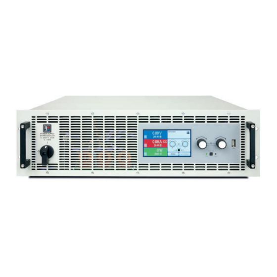
Seite 18: Ansichten
PSI 9000 3U Serie 1.8.4 Ansichten Bild 1 - Vorderseite Bild 2 - Rückseite (Standardausführung) EA Elektro-Automatik GmbH Telefon: 02162 / 3785-0 www.elektroautomatik.de Seite 18 Helmholtzstr. 31-33 • 41747 Viersen Telefax: 02162 / 16230 ea1974@elektroautomatik.de... - Seite 19 PSI 9000 3U Serie EA Elektro-Automatik GmbH Telefon: 02162 / 3785-0 www.elektroautomatik.de Seite 19 Helmholtzstr. 31-33 • 41747 Viersen Telefax: 02162 / 16230 ea1974@elektroautomatik.de...
- Seite 20 PSI 9000 3U Serie Bild 5 - Ansicht von oben EA Elektro-Automatik GmbH Telefon: 02162 / 3785-0 www.elektroautomatik.de Seite 20 Helmholtzstr. 31-33 • 41747 Viersen Telefax: 02162 / 16230 ea1974@elektroautomatik.de...
-
Seite 21: Anzeige Mit Berührungsempfindlicher Oberfläche (Touchscreen)
PSI 9000 3U Serie Bild 6 - Bedienfeld Übersicht der Bedienelemente am Bedienfeld Für eine genaue Erläuterung siehe Abschnitte „1.9.6. Die Bedieneinheit (HMI)“. Anzeige mit berührungsempfindlicher Oberfläche (Touchscreen) Dient zur Auswahl von Sollwerten, Menüs, Zuständen, sowie zur Anzeige der Istwerte und des Status. -
Seite 22: Aufbau Und Funktion
1.9.1 Allgemeine Beschreibung Die elektronischen Hochleistungsnetzgeräte der Serie PSI 9000 3U sind durch ihre recht kompakten 19“-Ein- schubgehäuse mit 3 Höheneinheiten (3U) besonders für Prüfsysteme und Industriesteuerungen geeignet. Über die gängigen Funktionen von Stromversorgungen hinaus können mit dem integrierten Funktionsgenerator sinus-, rechteck- oder dreieckförmige Sollwertkurven sowie weitere Kurvenformen erzeugt werden. -
Seite 23: Lieferumfang
PSI 9000 3U Serie 1.9.3 Lieferumfang 1 x Netzgerät 1 x Gedruckte Betriebsanleitung 1 x Stecker für Share-Bus 1 x Stecker für Fernfühlung 1 x USB-Kabel 1,8 m 1 x Set DC-Klemmenabdeckung 1 x CD „Drivers & Tools“ 1 x AC-Anschlußstecker (Klemmtyp) 1 x Set für Zugentlastung... -
Seite 24: Die Bedieneinheit (Hmi)
PSI 9000 3U Serie 1.9.6 Die Bedieneinheit (HMI) HMI steht für Human Machine Interface, auf deutsch Mensch-Maschine-Schnittstelle, und besteht hier aus einer Anzeige mit berührungsempfindlicher Oberfläche (Touchscreen), zwei Drehknöpfen, einem Taster und einem USB-Port Typ A. 1.9.6.1 Anzeige mit Touchscreen Die grafische Anzeige mit Touchscreen ist in mehrere Bereiche aufgeteilt. Die gesamte Oberfläche ist berührungs-... -
Seite 25: Tastfunktion Der Drehknöpfe
PSI 9000 3U Serie • Statusanzeigen (oben rechts) Dieses Feld zeigt diverse Statustexte und -symbole an: Anzeige Beschreibung Gesperrt Das HMI ist gesperrt Entsperrt Das HMI ist nicht gesperrt Fern: Das Gerät befindet sich in Fernsteuerung durch... Analog ...die eingebaute Analogschnittstelle USB & andere ...die eingebaute USB-Schnittstelle oder steckbares Schnittstellenmodul Lokal Das Gerät ist durch Benutzereingabe explizit gegen Fernsteuerung gesperrt worden... -
Seite 26: Auflösung Der Anzeigewerte
PSI 9000 3U Serie 1.9.6.4 Auflösung der Anzeigewerte In der Anzeige können Sollwerte in festgelegten Schrittweiten eingestellt werden. Die Anzahl der Nachkommastellen hängt vom Gerätemodell ab. Die Werte haben 3 bis 5 Stellen. Ist- und Sollwerte haben die gleiche Stellenanzahl. -
Seite 27: Usb-Port Typ B (Rückseite)
PSI 9000 3U Serie 1.9.7 USB-Port Typ B (Rückseite) Der USB-Port Typ B auf der Rückseite des Gerätes dient zur Kommunikation mit dem Gerät, sowie zur Firmwareaktualisierung. Über das mitgelieferte USB-Kabel kann das Gerät mit einem PC verbunden werden (USB 2.0, USB 3.0). Der Treiber wird auf CD mitgeliefert und installiert einen virtuellen COM-Port. -
Seite 28: Share-Bus-Anschluß
PSI 9000 3U Serie 1.9.10 Share-Bus-Anschluß Diese auf der Rückseite des Gerätes befindliche, 2polige WAGO-Buchse („Share“) dient zur Verbindung mit der gleichnamigen Buchse an kompatiblen Netzgeräten, um Parallelschaltung eine gleichmäßigen Laststromaufteilung zu erreichen. Sie dient auch zur Verbindung mit dem Share-Anschluß kompatibler elektronischer Lasten, um einen Zwei-Quadranten-Betrieb herzustellen. Folgende Netzgeräteserien und elektronische Lastserien sind kompatibel: • PSI 9000 2U... -
Seite 29: Installation & Inbetriebnahme
PSI 9000 3U Serie Installation & Inbetriebnahme Transport und Lagerung 2.1.1 Transport • Die Griffe an der Vorderseite des Gerätes dienen nicht zum Tragen! • Das Gerät sollte aufgrund seines hohen Gewichts, je nach Modell, möglichst nicht per Hand transportiert werden bzw. darf, falls Transport per Hand nicht vermeidbar ist, nur am Gehäuse und nicht an den Aufbauten (Griffe, DC-Ausgangsklemme, Drehknöpfe) gehalten werden... -
Seite 30: Vorbereitung
2.3.2 Vorbereitung Für das netzseitige Anschließen des Netzgerätes der Serie PSI 9000 3U ist ein 5poliger Anschlußstecker auf der Rückseite vorgesehen (im Lieferumfang enthalten). Für die Verkabelung des Steckers ist eine mindestens 3polige (L1+L3+PE), je nach Modell auch bis zu 4polige Zuleitung (L1+L2+L3+PE) mit entsprechendem Querschnitt und Länge vorzusehen. -
Seite 31: Anschließen An Das Stromnetz (Ac)
PSI 9000 3U Serie 2.3.4 Anschließen an das Stromnetz (AC) • Das Anschließen an eine AC-Stromversorgung darf nur durch entsprechend geschultes Per- sonal erfolgen! • Dimensionieren Sie den Querschnitt von Anschlußleitungen entsprechend des maximalen Eingangsstromes des Gerätes (siehe Tabelle)! • Stellen Sie vor dem Anstecken des Netzanschlußsteckers sicher, daß das Gerät am Netz- schalter ausgeschaltet ist! Das Gerät wird mit einem 5poligen Netzanschlußstecker geliefert. -
Seite 32: Anschließen Von Dc-Lasten
PSI 9000 3U Serie 2.3.5 Anschließen von DC-Lasten • Bei einem Gerät mit hohem Nennstrom und demzufolge entsprechend dicken und schweren DC-Anschlußleitungen sind das Gewicht der Leitungen und die Belastung des DC-Anschlus- ses am Gerät zu beachten und besonders bei Installation des Gerätes in einem 19"-Schrank oder ähnlich, wo die Leitungen am DC-Ausgang hängen, Zugentlastungen anzubringen. -
Seite 33: Erdung Des Dc-Ausgangs
PSI 9000 3U Serie Der Anschlußwinkel und der erforderliche Knickradius für die DC-Zuleitungen sind zu berück- sichtigen, wenn die Gesamttiefe des Gerätes geplant werden soll, besonders beim Einbau in 19“-Schränke und ähnlichen. Bei Anschlußklemme Typ 2 ist z. B. nur das horizontale Zuführen der DC-Leitungen möglich, damit die Abdeckung installiert werden kann. -
Seite 34: Installation Eines Anybus-Schnittstellenmoduls
2.3.8 Installation eines AnyBus-Schnittstellenmoduls Die diversen Schnittstellenmodule, die für die PSI 9000 3U-Modelle mit Slot (nur in der Standardausführung) ver- fügbar sind, können durch den Anwender nachgerüstet werden und sind durch andere Module austauschbar. Die Einstellungen zum momentan installierten Modul variieren und sollte nach der Erstinstallation bzw. nach Wechsel des Modultyps überprüft und ggf. -
Seite 35: Anschließen Der Analogen Schnittstelle
PSI 9000 3U Serie 2.3.9 Anschließen der analogen Schnittstelle Der 15polige Anschluß (Typ: Sub-D, D-Sub) auf der Rückseite ist eine analoge Schnittstelle. Um diesen mit einer steuernden Hardware (PC, elektronische Schaltung) zu verbinden, ist ein handelsüblicher Sub-D-Stecker erforder- lich (nicht im Lieferumfang enthalten). Generell ist es ratsam, bei Verbindung oder Trennung dieses Anschlusses das Gerät komplett auszuschalten, mindestens aber den DC-Ausgang. -
Seite 36: Erstinbetriebnahme
PSI 9000 3U Serie 2.3.12 Erstinbetriebnahme Bei der allerersten Inbetriebnahme des Gerätes und der Erstinstallation sind zusätzliche Maßnahmen zu ergreifen: • Überprüfen Sie die von Ihnen verwendeten Anschlußkabel für AC und DC auf ausreichenden Querschnitt! • Überprüfen Sie die Einstellungen bezüglich Sollwerte, Sicherheits- und Überwachungsfunktionen sowie Kom- munikation daraufhin, daß... -
Seite 37: Bedienung Und Verwendung
PSI 9000 3U Serie Bedienung und Verwendung Personenschutz • Um Sicherheit bei der Benutzung des Gerätes zu gewährleisten, darf das Gerät nur von Per- sonen bedient werden, die über die erforderlichen Sicherheitsmaßnahmen im Umgang mit gefährlichen elektrischen Spannungen unterrichtet worden sind • Bei Geräten, die eine berührungsgefährliche Spannung erzeugen können oder an diese... -
Seite 38: Leistungsregelung / Konstantleistung / Leistungsbegrenzung
PSI 9000 3U Serie 3.2.3 Leistungsregelung / Konstantleistung / Leistungsbegrenzung Leistungsregelung, auch Leistungsbegrenzung oder Konstantleistung (kurz: CP) genannt, hält die DC-Ausgangsleistung bei Netzgeräten konstant auf dem einge- stellten Wert, wenn der in den Verbraucher fließende Strom in Zusammenhang mit der eingestellten Ausgangsspannung und dem Widerstand des Verbrauchers nach P = U * I bzw. -
Seite 39: Alarmzustände
PSI 9000 3U Serie Alarmzustände Dieser Abschnitt gibt nur eine Übersicht über mögliche Alarmzustände. Was zu tun ist im Fall, daß Ihr Gerät Ihnen einen Alarm anzeigt, wird in Abschnitt „3.6. Alarme und Überwachung“ erläutert. Grundsätzlich werden alle Alarmzustände optisch (Text + Meldung in der Anzeige), akustisch (wenn Alarmton aktiviert) und als auslesbarer Status, sowie Alarmzähler über digitale Schnittstelle signalisiert. -
Seite 40: Manuelle Bedienung
PSI 9000 3U Serie Manuelle Bedienung 3.4.1 Einschalten des Gerätes Das Gerät sollte möglichst immer am Netzschalter (Drehschalter, Vorderseite) eingeschaltet werden. Alternativ kann es über eine externe Trennvorrichtung (Hauptschalter, Schütz) mit entsprechender Strombelastbarkeit netz- seitig geschaltet werden. Nach dem Einschalten zeigt das Gerät für einige Sekunden in der Anzeige das Herstellerlogo und danach noch etwa drei Sekunden lang Herstellername, sowie Herstelleranschrift, Gerätetyp, Firmwareversion(en), Seriennummer und... - Seite 41 PSI 9000 3U Serie EA Elektro-Automatik GmbH Telefon: 02162 / 3785-0 www.elektroautomatik.de Seite 41 Helmholtzstr. 31-33 • 41747 Viersen Telefax: 02162 / 16230 ea1974@elektroautomatik.de...
- Seite 42 PSI 9000 3U Serie EA Elektro-Automatik GmbH Telefon: 02162 / 3785-0 www.elektroautomatik.de Seite 42 Helmholtzstr. 31-33 • 41747 Viersen Telefax: 02162 / 16230 ea1974@elektroautomatik.de...
- Seite 43 PSI 9000 3U Serie EA Elektro-Automatik GmbH Telefon: 02162 / 3785-0 www.elektroautomatik.de Seite 43 Helmholtzstr. 31-33 • 41747 Viersen Telefax: 02162 / 16230 ea1974@elektroautomatik.de...
-
Seite 44: Einstellung Fernsteuerung Erlauben
PSI 9000 3U Serie 3.4.3.1 Menü „Allgemeine Einstellungen“ Einstellung S. Beschreibung Fernsteuerung erlauben Bei Wahl „Nein“ kann das Gerät weder über eine der digitalen, noch über die analoge Schnittstelle fernbedient werden. Der Status, daß die Fernsteuerung gesperrt ist, wird im Statusfeld der Hauptanzeige mit „Lokal“ angezeigt. Siehe auch Abschnitt 1.9.6.1. - Seite 45 PSI 9000 3U Serie 3.4.3.2 Menü „Nutzer-Events“ Siehe „3.6.2.1 Benutzerdefinierbare Ereignisse (Events)“ auf Seite 57. 3.4.3.3 Menü „Profile“ Siehe „3.8 Nutzerprofile laden und speichern“ auf Seite 59. 3.4.3.4 Menü „Übersicht“ Diese Menüseiten zeigen eine Übersicht der aktuellen Sollwerte (U, I, P bzw. U, I, P, R) und Gerätealarmein- stellungen, sowie die Eventeinstellungen und Einstellgrenzen an.
-
Seite 46: Beschreibung
PSI 9000 3U Serie IF Ebene 1 Beschreibung Knoten-Adresse Einstellung der Profibus- oder Knotenadresse im Bereich von 1...125 per Direk- teingabe des Wertes Funktions-Beschreib. Texteingabefeld zur Eingabe eines beliebigen Textes zum Profibus-Tag „Funktions- beschreibung“ (Function tag). Max. Länge: 32 Zeichen Standort-Beschreib. Texteingabefeld zur Eingabe eines beliebigen Textes zum Profibus-Tag „Standort- beschreibung“ (Location tag). Max. Länge: 22 Zeichen Datum der Installation Texteingabefeld zur Eingabe eines beliebigen Textes zum Profibus-Tag „Installa- tiondatum“ (Installation date). Max. Länge: 40 Zeichen Beschreib. - Seite 47 PSI 9000 3U Serie IF Ebene 1 Ebene 2 Beschreibung Knoten-Adresse Einstellung der CANopen-Knotenadresse im Bereich von 1...127 per Direk- teingabe des Wertes Baud-Rate AUTO Automatische Erkennung der Busgeschwindigkeit Setzt die Bus-Baudrate und die Knotenadresse automatisch Manuell Manuelle Einstellung der Busgeschwindigkeit für die CANopen-Schnittstelle.
-
Seite 48: Einstellgrenzen (Limits)
3.4.5 Betriebsart wechseln Generell wird bei manueller Bedienung eines PSI 9000 3U zwischen zwei Betriebsarten unterschieden, die an die Sollwerteingabe per Drehknopf oder Zehnertastatur gebunden sind. Diese Zuordnung kann bzw. muß gewechselt werden, wenn einer der drei bzw. vier Sollwerte verstellt werden soll, der momentan nicht zugänglich ist. -
Seite 49: Sollwerte Manuell Einstellen
PSI 9000 3U Serie 3.4.6 Sollwerte manuell einstellen Die Einstellung der Sollwerte von Spannung, Strom und Leistung ist die grundlegende Bedienmöglichkeit eines Stromversorgungsgerätes und daher sind die beiden Drehknöpfe auf der Vorderseite des Gerätes bei manueller Bedienung stets zwei von diesen drei Sollwerten zugewiesen. -
Seite 50: Dc-Ausgang Ein- Oder Ausschalten
PSI 9000 3U Serie 3.4.7 DC-Ausgang ein- oder ausschalten Der DC-Ausgang des Gerätes kann manuell oder ferngesteuert aus- oder eingeschaltet werden. Bei manueller Bedienung kann dies jedoch durch die Bedienfeldsperre verhindert sein. Das manuelle oder ferngesteuerte (digital) Einschalten des DC-Ausgangs kann durch den Ein- gangspin REM-SB der eingebauten Analogschnittstelle gesperrt sein. -
Seite 51: Fernsteuerung
Phase „Lokal“ auf HIGH geändert, also auf „Fernsteuerung = aus“. 3.5.3 Fernsteuerung über eine digitale Schnittstelle 3.5.3.1 Schnittstellenwahl Die Standardausführungen der Serie PSI 9000 3U unterstützen zusätzlich zur serienmäßig eingebauten USB- Schnittstelle folgende optional erhältliche Schnittstellenmodule, unter denen der Anwender wählen kann: Kurzbezeichnung Art.nr. Ports Beschreibung* 35400100 CANopen... -
Seite 52: Programmierung
3.5.3.2 Allgemeines zu den Schnittstellenmodulen Bei den Standardausführungen der Serie PSI 9000 3U kann jeweils eins der in 3.5.3.1 genannten steck- und nachrüstbaren Module installiert sein. Dieses kann das Gerät alternativ zu der fest eingebauten USB-Schnittstelle (Rückseite, Typ B) oder der fest eingebauten Analogschnittstelle fernsteuern. Zur Installation siehe „1.9.8. Steck- platz für Schnittstellenmodule“... -
Seite 53: Quittieren Von Alarmmeldungen
PSI 9000 3U Serie 3.5.4.2 Quittieren von Alarmmeldungen Alarmmeldungen des Gerätes (siehe 3.6.2) erscheinen immer in der Anzeige, einige davon auch als Signal auf der analogen Schnittstelle (siehe Tabelle unten). Tritt während der Fernsteuerung über analoge Schnittstelle ein Gerätealarm auf, schaltet der DC-Ausgang ge- nauso aus wie bei manueller Bedienung. -
Seite 54: Übersicht Sub-D-Buchse
PSI 9000 3U Serie 3.5.4.4 Übersicht Sub-D-Buchse 3.5.4.5 Prinzipschaltbilder der Pins Analoger Eingang (AI) Digitaler Eingang (DI) Hochohmiger Eingang (Impedanz: Es ist ein möglichst niederohmiger Schal- >40 k...100 kΩ) einer OP-Schaltung. V~0.5 ter zu verwenden ist (Relaiskontakt, Schalter, Schütz o.ä.), um das Signal sauber nach DGND zu schalten. - Seite 55 PSI 9000 3U Serie • Fernsteuerung wurde nicht aktiviert In diesem Modus stellt der Pin eine Art Freigabe der Taste „On/Off“ am Bedienfeld des Gerätes bzw. des Befehls „DC-Ausgang ein/aus“ (bei digitaler Fernsteuerung) dar. Daraus ergeben sich folgende mögliche Situationen: Parameter ...
-
Seite 56: Alarme Und Überwachung
PSI 9000 3U Serie Alarme und Überwachung 3.6.1 Begriffsdefinition Grundsätzlich wird unterschieden zwischen Gerätealarmen (siehe „3.3. Alarmzustände“), wie Überspannung oder Übertemperatur, und benutzerdefinierten Ereignissen wie z. B. OVD (Überspannungsüberwachung). Während Gerätealarme, bei denen der DC-Ausgang zunächst ausgeschaltet wird, zum Schutz des Gerätes und der ange- schlossenen Last dienen, können benutzerdefinierte Ereignisse den DC-Ausgang abschalten (bei Aktion ALARM),... -
Seite 57: Ereignis Bedeutung
PSI 9000 3U Serie Diese Gerätealarme können nicht konfiguriert werden, da hardwaremäßig bedingt: Alarm Bedeutung Beschreibung Meldeorte Netzunter- oder überspannung. Löst einen Alarm aus, wenn die AC- Versorgung außerhalb der Spezifikationen des Gerätes arbeiten sollte Anzeige, Power Fail (Spannung/Frequenz) oder wenn das Gerät von der AC-Versorgung Digitale Schnitt- getrennt wird, z. B. durch Ausschalten am Netzdrehschalter. Außerdem stellen wird der DC-Ausgang ausgeschaltet. -
Seite 58: Bedieneinheit (Hmi) Sperren
PSI 9000 3U Serie ► So konfigurieren Sie die Events Tippen Sie in der Hauptseite auf das Bedienfeld Tippen Sie auf der rechten Seite auf die weißen dreieckigen Pfeile , um „4.1 Event U“ oder „4.2 Event I“ oder „4.3 Event P“ auszuwählen. -
Seite 59: Nutzerprofile Laden Und Speichern
PSI 9000 3U Serie Nutzerprofile laden und speichern Das Menü „Profile“ dient zur Auswahl eines Profils zum Laden bzw. zum Wechsel zwischen einem Standardprofil und 5 Nutzerprofilen. Ein Profil ist eine Sammlung aller Einstellungen und aller Sollwerte. Bei Auslieferung des Gerätes bzw. nach einem Zurücksetzungsvorgangs haben alle sechs Profile dieselben Einstellungen und sämtliche Sollwerte sind auf 0. Werden vom Anwender dann Einstellungen getroffen und Werte verändert, so geschieht das in einem Arbeitsprofil, das auch über das Ausschalten hinweg gespeichert wird. Dieses Arbeitsprofil kann in eins der fünf Nutzerprofile gespeichert bzw. aus diesen fünf Nutzerprofilen oder aus dem Standardprofil heraus gela- den werden. Das Standardprofil selbst kann nur geladen werden. Wenn das Arbeitsprofil aus dem Standardprofil heraus geladen und überschrieben wird, entspricht das dem Zurücksetzen des Gerätes. -
Seite 60: Der Funktionsgenerator
PSI 9000 3U Serie Der Funktionsgenerator 3.9.1 Einleitung Der eingebaute Funktionsgenerator (kurz: FG) ist in der Lage, verschiedenförmige Signalformen zu erzeugen und diese auf einen der Sollwerte Spannung (U) oder Strom (I) anzuwenden. Bei manueller Bedienung können die Funktionen des Generators komplett bedient werden. Bei Fernsteuerung sind nur der Arbiträrgenerator und eine XY-Funktion verfügbar. -
Seite 61: Mögliche Technische Komplikationen
PSI 9000 3U Serie 3.9.2.3 Auflösung X (Zeit) und Y (Amplitude) Das Gerät kann zwischen 0...100% Nennwert max. 3276 Schritte setzen. Die möglichen Zwischenwerte, die ge- setzt werden müssen, um einen linearen oder andersartigen Anstieg/Abfall zu erreichen, werden in Abhängigkeit von der Amplitude berechnet und gesetzt. -
Seite 62: Sinus-Funktion
PSI 9000 3U Serie Nachdem die Einstellungen getroffen wurden, muß die Funktion geladen werden. ► So laden Sie eine Funktion Nachdem Sie die Werte für das zu generierende Signal eingestellt haben, tippen Sie auf Das Gerät lädt daraufhin die Daten in die internen Regelung und wechselt die Anzeige. -
Seite 63: Dreieck-Funktion
PSI 9000 3U Serie 3.9.6 Dreieck-Funktion Folgende Parameter können für die Dreieck-Funktion konfiguriert werden: Wert Einstellbereich Erläuterung I(A), U(A) 0...(Nennwert - (Off)) von U, I A = Amplitude des zu generierenden Signals I(Off), U(Off) 0...(Nennwert - (A)) von U, I Off = Offset, bezogen auf den Fußpunkt des Dreiecks 0,1 ms...36000 s... -
Seite 64: Trapez-Funktion
PSI 9000 3U Serie 3.9.8 Trapez-Funktion Folgende Parameter können für die Trapez-Funktion konfiguriert werden: Wert Einstellbereich Erläuterung I(A), U(A) 0...(Nennwert - (Off)) von U, I A = Amplitude des zu generierenden Signals I(Off), U(Off) 0...(Nennwert - (A)) von U, I Off = Offset, bezogen auf den Fußpunkt des Trapezes 0,1 ms...36000 s... -
Seite 65: Arbiträr-Funktion
PSI 9000 3U Serie 3.9.10 Arbiträr-Funktion Die Arbiträr-Funktion (arbiträr = beliebig) bietet dem Anwender einen erweiterten Spielraum. Es sind je 100 Se- quenzen für die Zuordnung zum Strom I und der Spannung U verfügbar, die alle mit den gleichen Parametern versehen sind, aber durch die Werte unterschiedlich konfiguriert werden können, um so komplexe Funktionsabläufe... - Seite 66 PSI 9000 3U Serie Bildliche Darstellungen: Anwendungen und Resultate: Beispiel 2 Betrachtung 1 Ablaufs 1 Sequenz aus 100: Die DC-Werte von Start und Ende sind gleich, die AC-Werte (Ampli- tude) jedoch nicht. Der Endwert ist größer als der Startwert, daher wird die Amplitude mit jeder neu angefangenen Sinushalbwelle kon- tinuierlich zwischen Anfang und Ende der Sequenz größer.
- Seite 67 PSI 9000 3U Serie Durch Aneinanderreihung mehrerer unterschiedlich konfigurierter Sequenzen können komplexe Abläufe erzeugt werden. Dabei kann durch geschickte Konfiguration der Arbiträrgenerator die anderen Funktionen wie Dreieck, Sinus, Rechteck oder Trapez nachbilden und somit z. B. eine Sequenz aus Rechteck-Funktionen mit unterschied- lichen Amplituden bzw. Duty Cycles pro Sequenz erzeugen. Durch die Zuordnung zu U oder I sind die jeweils 100 verfügbaren Sequenzen entweder nur auf den Strom oder die Spannung anwendbar und nicht vermischbar.
-
Seite 68: Laden Und Speichern Von Arbiträr-Funktionen
PSI 9000 3U Serie 3.9.10.1 Laden und Speichern von Arbiträr-Funktionen Die manuell am Gerät konfigurierbaren 100 Sequenzen der Arbiträrfunktion, die auf Spannung U oder Strom I anwendbar ist, können über die USB-Schnittstelle auf der Vorderseite des Gerätes auf einen USB-Stick (FAT32- formatiert) gespeichert oder von diesem geladen werden. Dabei gilt, daß beim Speichern immer alle 100 Sequenzen in eine Textdatei vom Typ CSV gespeichert werden, beim Laden umgekehrt genauso. -
Seite 69: Rampen-Funktion
PSI 9000 3U Serie ► So speichern Sie die 100 Sequenzen vom Gerät auf einen USB-Stick: Stecken Sie den USB-Stick noch nicht ein bzw. ziehen Sie ihn zunächst heraus. Öffnen Sie das Funktionsauswahlmenü des Funktionsgenerators über MENU -> Funkt.Generator -> Arbiträr -> U / I... -
Seite 70: Laden Von Ui- Und Iu-Tabellen Über Usb
PSI 9000 3U Serie Bei der IU-Funktion ist die Zuordnung von Meßwert zum aus der Tabelle entnommenen Wert genau andersherum als bei der UI-Funktion, das Verhalten jedoch das gleiche. Man könnte somit das Verhalten der Last bzw. die Strom- und Leistungsaufnahme in Abhängigkeit von der Aus- gangsspannung steuern und Lastsprünge erzeugen. -
Seite 71: Pv-Tabellenfunktion (Photovoltaik)
PSI 9000 3U Serie 3.9.13 PV-Tabellenfunktion (Photovoltaik) 3.9.13.1 Einleitung Diese Funktion nutzt den internen XY-Generator, um mit einer aus vier Einstell- werten generierten IU-Tabelle das Netzgerät dazu zu bringen, ein Solarpanel oder eine Solarzelle mit bestimmten Eigenschaften zu simulieren, um damit Solarwechselrichter zu testen. -
Seite 72: Fc-Tabellenfunktion (Brennstoffzelle)
PSI 9000 3U Serie Die Veränderung verschiebt den MPP und die Kurve auf der Y-Achse. Siehe Abbildung rechts. Der Wert Bestrahlung ist dabei ein Faktor für Impp. Die Kurve an sich wird dabei nicht verändert oder neu berechnet. ► So konfigurieren Sie die PV-Tabelle Im Funktionsgenerator-Auswahlmenü... - Seite 73 PSI 9000 3U Serie 3.9.14.2 Anwendung Folgende Parameter können für die FC-Tabellenfunktion konfiguriert werden: Wert Einstellbereich Erläuterung Punkt 1: Uoc 0 V...U Open circuit voltage, Leerlaufspannung Nenn Punkt 2+3: U 0 V...U Spannung und Strom der beiden Punkte im U-I-Koordinatensy- Nenn stem. Sie repräsentieren zwei Stützpunkte auf der zu errech- Punkt 2+3: I 0 A...I...
-
Seite 74: Fernsteuerung Des Funktionsgenerators
PSI 9000 3U Serie 3.9.15 Fernsteuerung des Funktionsgenerators Der Funktionsgenerator ist fernsteuerbar, allerdings geschehen die Konfiguration und Steuern von Funktionen mittels einzelner Befehle und prinzipiell anders als bei manueller Bedienung. Die externe Dokumentation „Pro- grammieranleitung ModBus & SCPI“ erläutert die Vorgehensweise. Folgendes gilt generell: • Der Funktionsgenerator ist nicht über die analoge Schnittstelle fernbedienbar • Der Funktionsgenerator ist nicht verfügbar, wenn Geräte im Widerstands-Betrieb (R-Modus) arbeiten... -
Seite 75: Weitere Anwendungen
PSI 9000 3U Serie 3.10 Weitere Anwendungen 3.10.1 Parallelschaltung als Master-Slave (MS) Mehrere Geräte gleicher Art und gleichen Modells können zu einer Parallelschaltung verbunden werden, um eine höhere Gesamtleistung zu erzielen. Dabei werden üblicherweise alle Netzgeräte an ihren DC-Ausgängen verbun- den, sowie zusätzlich der Share-Bus und der digitalen Master-Slave-Bus aller Einheiten. -
Seite 76: Stellung: Terminiert
PSI 9000 3U Serie ► So stellen Sie die digitale Master-Slave-Verbindung her Alle zu verbindenden Geräte ausschalten und mittels Netzwerkkabel (CAT3 oder besser, nicht im Lieferum- fang des Gerätes enthalten) untereinander verbinden. Dabei ist es egal, welche der beiden Master-Slave- Busanschlüsse (RJ45, Rückseite) zum jeweils nächsten Gerät verbunden werden. -
Seite 77: Bedienung Des Master-Slave-Systems
PSI 9000 3U Serie 3.10.1.4 Bedienung des Master-Slave-Systems Nach erfolgreicher Initialisierung des Master-Gerätes und der Slave-Geräte zeigen diese ihren Status in der Anzeige an. Der Master zeigt lediglich „Master“ im Statusfeld, die Slaves zeigen, solange wie durch den Master ferngesteuert, dies an:... -
Seite 78: Reihenschaltung
PSI 9000 3U Serie In Situationen, wo ein oder mehrere Geräte einen Gerätealarm wie OV oder PF erzeugen, gilt Folgendes: • Jeder Gerätealarm eines Slaves wird auf dem Display des Slaves und auf dem des Masters angezeigt. • Bei gleichzeitig auftretenden Alarmen mehrerer Slaves zeigt der Master nur den zuletzt aufgetretenen Alarm an. -
Seite 79: Zwei-Quadranten-Betrieb (2Qb)
Diese Betriebsart bezieht sich auf die Verwendung einer Quelle, in dem Fall ein Netzgerät der Serie PSI 9000 3U, und einer Senke, in dem Fall eine elektronische Last der Serie ELR 9000. Die Quelle und die Senke treten abwechselnd in Funk- tion, um einen Prüfling, wie z. B. eine Batterie, im Rahmen eines Funktions- oder... -
Seite 80: Einstellungen An Den Geräten
PSI 9000 3U Serie Konfiguration C: E-LOAD n PSU n Mehrere E-Lasten und mehrere Netzgeräte, plus ein Prüfling (E.U.T), zur Aufstockung für höhere Gesamtleistung. Der Lastenverbund und der Netzgeräteverbund bilden jeder für sich ein Gesamtsystem mit einer bestimmten Leistung. Auch hier gilt: die Nennwerte der beiden Systeme müssen... -
Seite 81: Instandhaltung & Wartung
PSI 9000 3U Serie Instandhaltung & Wartung Wartung / Reinigung Die Gerät erfordern keine Wartung. Reinigung kann, jenachdem in welcher Umgebung sie betrieben werden, frü- her oder später für die internen Lüfter nötig sein. Diese dienen zur Kühlung der internen Komponenten, die durch die zwangsweise entstehende, jedoch geringe Verlustleistung erhitzt werden. -
Seite 82: Firmwareaktualisierung (Updates)
Öffnen Sie das neue Laufwerk mit einem Programm wie den Windows Explorer. In dem Laufwerk muß eine Datei namens „firmware.bin“ sein. Löschen Sie diese. Kopieren Sie die neue Firmware-Datei (*.bin), die Sie für Ihr Gerät von der Elektro-Automatik Webseite geladen haben, in das Laufwerk. Warten Sie, bis der Kopiervorgang abgeschlossen ist. -
Seite 83: Nachjustierung (Kalibrierung)
PSI 9000 3U Serie Nachjustierung (Kalibrierung) 4.4.1 Einleitung Die Geräte der Serie PSI 9000 verfügen über eine Nachjustierungsfunktion, die im Rahmen einer Kalibrierung dazu dient, Abweichungen zwischen den Stellwerten und tatsächlichen Werten bis zu einem gewissen Grad zu kompensieren. Gründe, die eine Nachjustierung der Gerätestellwerte nötig machen, gibt es einige: Bauteilalterung, Bauteilverschleiß, extreme Umgebungsbedingungen, häufige Benutzung. - Seite 84 PSI 9000 3U Serie 4.4.3.1 Sollwerte ► So gleichen Sie die Spannung ab Spannungsmeßgerät am DC-Ausgang anschließen. Die Last auf etwa 5% des Nennstromes des Netzgerätes, hier ~8 A, und 0 V (falls elektro- nische Last) einstellen. In der Anzeige des PSI in das MENU wechseln, dann „Allg. Einstellun- gen“, dann Seite 6 und auf START.
-
Seite 85: Speichern Und Beenden
PSI 9000 3U Serie 4.4.3.3 Speichern und beenden Zum Schluß kann noch über das Bedienfeld das Datum des Abgleichs im Format JJJJ / MM / TT ein- gegeben und auch abgerufen werden. Danach sollten die Abgleichwerte unbedingt noch mit dem Bedienfeld gespeichert werden. -
Seite 86: Zubehör Und Optionen
PSI 9000 3U Serie Zubehör und Optionen Übersicht Zubehör und Optionen werden, sofern nötig, mit eigener Dokumentation geliefert und werden in diesem Dokument nicht näher erläutert. Service & Support Übersicht Reparaturen, falls nicht anders zwischen Anwender und Lieferant ausgemacht, werden durch den Hersteller durch- geführt. - Seite 88 EA-Elektro-Automatik GmbH & Co. KG Entwicklung - Produktion - Vertrieb Helmholtzstraße 31-33 41747 Viersen Telefon: 02162 / 37 85-0 Telefax: 02162 / 16 230 ea1974@elektroautomatik.de www.elektroautomatik.de...
- Seite 89 Operating Guide PSI 9000 3U DC High Efficiency Power Supply Attention! This document is only valid for devices with TFT display and firmware “KE: 2.09”, “HMI: 2.01” and “DR: 1.6.3” or Doc ID: PSI93UTEN higher. For availability of up- dates for your device check our Revision: 02 website or contact us.
- Seite 91 PSI 9000 3U Series TABLE OF CONTENTS GENERAL About this document ........5 2.3.8 Connection of remote sense .......33 1.1.1 Retention and use ..........5 2.3.9 Installation of an AnyBus interface module .34 1.1.2 Copyright ............5 2.3.10 Connecting the analog interface ....35 1.1.3...
- Seite 92 PSI 9000 3U Series 3.9.10 Arbitrary function ..........63 3.9.11 Ramp function ..........67 3.9.12 UI and IU table functions (XY table) ....67 3.9.13 PV table function (photovoltaics) ....69 3.9.14 FC table function (fuel cell) ......70 3.9.15 Remote control of the function generator..72 3.10...
-
Seite 93: General
EA Elektro-Automatik guarantees the functional competence of the applied technology and the stated performance parameters. The warranty period begins with the delivery of free from defects equipment. Terms of guarantee are included in the general terms and conditions (TOS) of EA Elektro-Automatik. Limitation of liability All statements and instructions in this manual are based on current norms and regulations, up-to-date technology and our long term knowledge and experience. -
Seite 94: Disposal Of Equipment
PSI 9000 3U Series Disposal of equipment A piece of equipment which is intended for disposal must, according to European laws and regulations (ElektroG, WEEE) be returned to the manufacturer for scrapping, unless the person operating the piece of equipment or an- other, delegated person is conducting the disposal. -
Seite 95: Safety
PSI 9000 3U Series Safety 1.7.1 Safety notices Mortal danger - Hazardous voltage • Electrical equipment operation means that some parts can be under dangerous voltage. Therefore all parts under voltage must be covered! This basically applies to all models, though 40 V models according to SELV can’t generate hazardous DC voltage. -
Seite 96: Responsibility Of The Operator
PSI 9000 3U Series 1.7.3 Responsibility of the operator Operator is any natural or legal person who uses the equipment or delegates the usage to a third party, and is responsible during its usage for the safety of the user, other personnel or third parties. -
Seite 97: Alarm Signals
PSI 9000 3U Series 1.7.5 Alarm signals The equipment offers various possibilities for signalling alarm conditions, however, not for danger situations. The signals may be optical (on the display as text), acoustic (piezo buzzer) or electronic (pin/status output of an analog interface). -
Seite 98: Specific Technical Data
PSI 9000 3U Series 1.8.3 Specific technical data Model 3U 3.3 kW / 5 kW PSI 9040-170 PSI 9080-170 PSI 9200-70 PSI 9360-40 PSI 9500-30 AC Input Input voltage 340...460 V AC 340...460 V AC 340...460 V AC 340...460 V AC 340...460 V AC... - Seite 99 PSI 9000 3U Series Model 3U 3.3 kW / 5 kW PSI 9040-170 PSI 9080-170 PSI 9200-70 PSI 9360-40 PSI 9500-30 Internal resistance regulation Adjustment range 0...7 Ω 0...14 Ω 0...85 Ω 0...270 Ω 0...500 Ω Accuracy ≤2% of max. resistance ± 0.3% of maximum current Display: Resolution See section „1.9.6.4.
- Seite 100 PSI 9000 3U Series Model 3U 5 kW / 6.6 kW / 10 kW PSI 9750-20 PSI 9040-340 PSI 9040-510 PSI 9080-340 PSI 9200-140 AC Input Input voltage 340...460 V AC 340...460 V AC 340...460 V AC 340...460 V AC 340...460 V AC...
- Seite 101 PSI 9000 3U Series Model 3U 5 kW / 6.6 kW / 10 kW PSI 9750-20 PSI 9040-340 PSI 9040-510 PSI 9080-340 PSI 9200-140 Internal resistance regulation Adjustment range 0...1125 Ω 0...3,5 Ω 0...2 Ω 0...7 Ω 0...42 Ω Accuracy ≤2% of max.
- Seite 102 PSI 9000 3U Series Model 3U 10 kW / 15 kW PSI 9360-80 PSI 9500-60 PSI 9750-40 PSI 91000-30 PSI 9080-510 AC Input Input voltage 340...460 V AC 340...460 V AC 340...460 V AC 340...460 V AC 340...460 V AC...
- Seite 103 PSI 9000 3U Series Model 3U 10 kW / 15 kW PSI 9360-80 PSI 9500-60 PSI 9750-40 PSI 91000-30 PSI 9080-510 Internal resistance regulation Adjustment range 0...135 Ω 0...250 Ω 0...562 Ω 0...1000 Ω 0...5 Ω Accuracy ≤ 2% of max. resistance ± 0.3% of maximum current Display: Resolution See section „1.9.6.4.
- Seite 104 PSI 9000 3U Series Model 3U 15 kW PSI 9200-210 PSI 9360-120 PSI 9500-90 PSI 9750-60 PSI 91500-30 AC Input Input voltage 340...460 V AC 340...460 V AC 340...460 V AC 340...460 V AC 340...460 V AC Input connection 3ph,PE...
- Seite 105 PSI 9000 3U Series Model 3U 15 kW PSI 9200-210 PSI 9360-120 PSI 9500-90 PSI 9750-60 PSI 91500-30 Internal resistance regulation Adjustment range 0...28 Ω 0...90 Ω 0...166 Ω 0...375 Ω 0...1500 Ω Accuracy ≤ 2% of max. resistance ± 0.3% of maximum current Display: Resolution See section „1.9.6.4.
-
Seite 106: Views
PSI 9000 3U Series 1.8.4 Views Figure 1 - Front side Figure 2 - Back side (standard version) EA Elektro-Automatik GmbH Fon: +49 2162 / 3785-0 www.elektroautomatik.de Page 18 Helmholtzstr. 31-33 • 41747 Viersen Fax: +49 2162 / 16230 ea1974@elektroautomatik.de... - Seite 107 PSI 9000 3U Series EA Elektro-Automatik GmbH Fon: +49 2162 / 3785-0 www.elektroautomatik.de Page 19 Helmholtzstr. 31-33 • 41747 Viersen Fax: +49 2162 / 16230 ea1974@elektroautomatik.de Germany...
- Seite 108 PSI 9000 3U Series Figure 5 - View from above EA Elektro-Automatik GmbH Fon: +49 2162 / 3785-0 www.elektroautomatik.de Page 20 Helmholtzstr. 31-33 • 41747 Viersen Fax: +49 2162 / 16230 ea1974@elektroautomatik.de Germany...
- Seite 109 PSI 9000 3U Series Figure 6 - Control Panel Overview of the elements of the operating panel For a detailed description see section „1.9.6. The control panel (HMI)“. Touchscreen display Used for selection of set values, menus, conditions and display of actual values and status.
-
Seite 110: Construction And Function
1.9.1 General description The electronic high performance power supplies of the PSI 9000 3U series are especially suitable for test systems and industrial controls due to their compact construction in a 19” enclosure with 3 height units (3U). Apart from basic functions of power supplies, set point curves can be produced in the integrated function generator (sine, rectangular, triangular and other curve types). -
Seite 111: Scope Of Delivery
PSI 9000 3U Series 1.9.3 Scope of delivery 1 x Power supply device 1 x Printed operating guide 1 x Share Bus plug 1 x Remote sensing plug 1 x 1.8 m USB cable 1 x Set of DC terminal covers 1 x CD “Drivers &... -
Seite 112: The Control Panel (Hmi)
PSI 9000 3U Series 1.9.6 The control panel (HMI) The HMI (Human Machine Interface) consists of a display with touchscreen, two rotary knobs, a pushbutton and a USB-A port. 1.9.6.1 Touchscreen display The graphic touchscreen display is divided into a number of areas. The complete display is touch sensitive and can be operated by finger or stylus to control the equipment. -
Seite 113: Rotary Knobs
PSI 9000 3U Series • Status display (upper right) This area displays various status texts and symbols: Display Description Locked The HMI is locked Unlocked The HMI is unlocked Remote: The device is under remote control from..Analog ..the built-in analog interface USB &... - Seite 114 PSI 9000 3U Series 1.9.6.4 Resolution of the displayed values In the display, set values can be adjusted in fixed increments. The number of decimal places depends on the device model. The values have 3 to 5 digits. Actual and set values always have the same number of digits.
-
Seite 115: Usb Port Type B (Rear Side)
PSI 9000 3U Series 1.9.7 USB port type B (rear side) The USB-B port on the back side of the device is provided for communication with the device and for firmware updates. The included USB cable can be used to connect the device to a PC (USB 2.0 or 3.0). -
Seite 116: Share" Connector
PSI 9000 3U Series 1.9.10 “Share” connector The 2 pole WAGO socket (“Share”) on the back side of the device is provided for connection to equally named sockets on compatible power supplies series to achieve a balanced load current distribution during parallel connection. The socket is also used to connect the power supply to compatible electronic loads, in order to build a two-quadrants operation setup. -
Seite 117: Installation & Commissioning
PSI 9000 3U Series Installation & commissioning Transport and storage 2.1.1 Transport • The handles on the front side of the device are not for carrying! • Because of its weight, transport by hand should be avoided where possible. If unavoidable then only the housing should be held and not on the exterior parts (handles, DC output terminal, rotary knobs). -
Seite 118: Preparation
Preparation Mains connection for the PSI 9000 3U series is done via the included 5 pole plug on the back of the device. Wiring of the plug is at least 3 strand (L1+L3+PE) or, for some models, 4 strand (L1+L2+L3+PE) of suitable cross section and length. -
Seite 119: Connection To Ac Supply
PSI 9000 3U Series 2.3.4 Connection to AC supply • Connection to an AC mains supply may only be carried out by qualified personnel! • Cable cross section must be suitable for the maximum input current of the device (see table below)! • Before plugging in the input plug ensure that the device is switched off by its mains switch! -
Seite 120: Connection To Dc Loads
PSI 9000 3U Series 2.3.5 Connection to DC loads • In the case of a device with a high nominal current and hence a thick and heavy DC connec- tion cable it is necessary to take account of the weight of the cable and the strain imposed on the DC connection. -
Seite 121: Grounding Of The Dc Output
PSI 9000 3U Series Examples of the type 1 terminal: • 90° up or down • space saving in depth • no bending radius • horizontal lead • space saving in height • large bending radius 2.3.6 Grounding of the DC output No matter if the power supply is operated stand-alone or in series connection with others, it is always only allowed to ground one of all DC output poles. -
Seite 122: Installation Of An Anybus Interface Module
Installation of an AnyBus interface module The various interface modules, which are available for PSI 9000 3U standard version models with Anybus slot, can be retrofitted by the user and are exchangeable with each other. The settings for the currently installed module vary and need to be checked and, if necessary, corrected on initial installation and after module exchange. -
Seite 123: Connecting The Analog Interface
PSI 9000 3U Series 2.3.10 Connecting the analog interface The 15 pole connector (Type: Sub-D, D-Sub) on the rear side is an analog interface. To connect this to a control- ling hardware (PC, electronic circuit), a standard plug is necessary (not included in the scope of delivery). It is generally advisable to switch the device completely off before connecting or disconnecting this connector, but at least the DC output. -
Seite 124: Operation And Application
PSI 9000 3U Series Operation and application Personal safety • In order to guarantee safety when using the device, it is essential that only persons operate the device who are fully acquainted and trained in the required safety measures to be taken when working with dangerous electrical voltages • For models which can generate a voltage which is dangerous by contact, or is connected to... -
Seite 125: Power Regulation / Constant Power / Power Limiting
PSI 9000 3U Series 3.2.3 Power regulation / constant power / power limiting Power regulation, also known as power limiting or constant power (CP), keeps the DC output power of a power supply constant if the current flowing to the load in relation to the output voltage and the resistance of load reaches the adjusted value according to P = U * I resp. -
Seite 126: Alarm Conditions
PSI 9000 3U Series Alarm conditions This section only gives an overview about device alarms. What to do in case your device indi- cates an alarm condition is described in section „3.6. Alarms and monitoring“. As a basic principle, all alarm conditions are signalled optically (text + message in the display), acoustically (if activated) and as a readable status and alarm counter via the digital interface. -
Seite 127: Manual Operation
PSI 9000 3U Series Manual operation 3.4.1 Switching on the device The device should, as far as possible, always be switched on using the rotary switch on the front of the device. Alternatively this can take place using an external cutout (contactor, circuit breaker) of suitable current capacity. - Seite 128 PSI 9000 3U Series EA Elektro-Automatik GmbH Fon: +49 2162 / 3785-0 www.elektroautomatik.de Page 40 Helmholtzstr. 31-33 • 41747 Viersen Fax: +49 2162 / 16230 ea1974@elektroautomatik.de Germany...
- Seite 129 PSI 9000 3U Series EA Elektro-Automatik GmbH Fon: +49 2162 / 3785-0 www.elektroautomatik.de Page 41 Helmholtzstr. 31-33 • 41747 Viersen Fax: +49 2162 / 16230 ea1974@elektroautomatik.de Germany...
- Seite 130 PSI 9000 3U Series EA Elektro-Automatik GmbH Fon: +49 2162 / 3785-0 www.elektroautomatik.de Page 42 Helmholtzstr. 31-33 • 41747 Viersen Fax: +49 2162 / 16230 ea1974@elektroautomatik.de Germany...
- Seite 131 PSI 9000 3U Series 3.4.3.1 Menu “General Settings” Setting P. Description Allow remote control Selection “NO” means that the device cannot be remotely controlled over either the digital or analog interfaces. If remote control is not allowed, the status will be shown as “local”...
- Seite 132 PSI 9000 3U Series 3.4.3.2 Menu “User Events” See „3.6.2.1 User defined events“ on page 56. 3.4.3.3 Menu “Profiles” See „3.8 Loading and saving a user profile“ on page 57. 3.4.3.4 Menu “Overview” This menu page displays an overview of the set values (U, I, P or U, I, P, R) and alarm settings as well as settings limits.
- Seite 133 PSI 9000 3U Series IF Level 1 Description Node Address Selection of the Profibus or node address of the device within range 1...125 via direct input Function Tag String input box for a user-definable text which describes the Profibus slave function tag.
- Seite 134 PSI 9000 3U Series IF Level 1 Level 2 Description Node Address Selection of the CANopen node address in the range 1...127 Baud Rate AUTO Automatic detection of the bus baud rate.(speed) Automatically sets baud rate and node address Manual Manual selection of the baud rate that is used by the CANopen interface.
-
Seite 135: Adjustment Limits
Changing the operating mode In general, the manual operation of a PSI 9000 3U distinguishes between two resp. three operating modes, U/I and U/P and U/R, which are tied to set value input using the rotary knobs or ten-key pad. This assignment must be changed if one of the three resp. -
Seite 136: Manual Adjustment Of Set Values
PSI 9000 3U Series 3.4.6 Manual adjustment of set values The set values for voltage, current and power are the fundamental operating possibilities of a power supply and hence the two rotary knobs on the front of the device are always assigned to two of the the values in manual operation. -
Seite 137: Switching The Dc Output On Or Off
PSI 9000 3U Series 3.4.7 Switching the DC output on or off The DC output of the device can be manually or remotely switched on and off. This can be restricted in manual operation by the control panel being locked. -
Seite 138: Remote Control
Remote control is possible via the built-in analog or USB port or via one of the optional interface modules (Any- Bus CompactCom, only with standard models of PSI 9000 3U series) or via the GPIB port (only with option 3W installed). -
Seite 139: Remote Control Via The Analog Interface (Ai)
General information about the interface modules With the standard models of series PSI 9000 3U, one of the plug-in and retrofittable modules listed in 3.5.3.1 can be installed. It can take over remote control of the device alternatively to the built-in USB type B on the back side or analog interface. - Seite 140 PSI 9000 3U Series 3.5.4.2 Acknowledging device alarms Device alarms (see 3.6.2) are always indicated in the front display and some of them are also reported as signal on the analog interface socket (see 3.5.4.3), for example the overvoltage alarm (OV), which is considered as critical.
-
Seite 141: Application Examples
PSI 9000 3U Series 3.5.4.4 Overview of the Sub-D Socket 3.5.4.5 Simplified diagram of the pins Digital Input (DI) Analog Input (AI) It requires to use a switch with low resist- High resistance input (impedance V~0.5 ance (relay, switch, circuit breaker etc.) in >40 k..100 kΩ) for an OA circuit. - Seite 142 PSI 9000 3U Series • Remote control is not active In this mode of operation pin “REM-SB” can serve as lock, preventing the DC output from being switched on by any means. This results in following possible situations: Parameter Behaviour output „REM-SB“...
-
Seite 143: Alarms And Monitoring
PSI 9000 3U Series Alarms and monitoring 3.6.1 Definition of terms There is a clear distinction between device alarms (see „3.3. Alarm conditions“) such as overvoltage protection or overheating protection, and user defined events such as OVD (overvoltage detection). Whilst device alarms serve to protect the device by initially switching off the DC output, user defined events can switch off the DC output (Ac- tion = ALARM), but can also simply give an acoustic signal to make the user aware. - Seite 144 PSI 9000 3U Series ► How to configure the device alarms Tap the touch area on the main screen. On the right side tap the white arrow to select “2. Protect”. Set the limits for the equipment alarm relevant to your application if the default value of 110% is unsuitable.
-
Seite 145: Control Panel (Hmi) Lock
PSI 9000 3U Series Control panel (HMI) lock In order to avoid the accidental alteration of a value during manual operation the rotary knobs or the touchscreen can be locked so that no alteration of values will be accepted without prior unlocking. -
Seite 146: The Function Generator
PSI 9000 3U Series The function generator 3.9.1 Introduction The built-in function generator (short: FG) is able to create various signal forms and apply these to the set value of voltage or current. In manual operation, all generator functions are available for access on the front panel. In remote control, only the customisable arbitrary generator and a XY function are available. -
Seite 147: Method Of Operation
PSI 9000 3U Series 3.9.2.3 Resolution of X (time) and Y (amplitude) The device can set 4096 steps between 0 ... 100% of nominal value. The intervals to create a linear or other rise/ fall are calculated depending on the amplitude and then set. -
Seite 148: Sine Wave Function
PSI 9000 3U Series After setting it up, the function can be loaded. ► How to load a function After setting the values for the required signal generation, tap on the touch area The device will then load the data into the internal controller and changes the display. -
Seite 149: Triangular Function
PSI 9000 3U Series 3.9.6 Triangular function The following parameters can be configured for a triangular wave function: Value Range Description I(A), U(A) 0...(Nominal value - (Off)) of U, I A = Amplitude of the signal to be generated I(Off), U(Off) 0...(Nominal value - (A)) of U, I Off = Offset, based on the foot of the triangular wave 0.1 ms...36000 s... -
Seite 150: Trapezoidal Function
PSI 9000 3U Series 3.9.8 Trapezoidal function The following parameters can be configured for a trapezoidal curve function: Value Range Description I(A), U(A) 0...(Nominal value - (Off)) of U, I A = Amplitude of the signal to be generated I(Off), U(Off) 0...(Nominal value - (A)) of U, I... -
Seite 151: Arbitrary Function
PSI 9000 3U Series 3.9.10 Arbitrary function The arbitrary (freely definable) function offers the user further scope. Up to 100 sequences are available for use for current I and voltage U, all of which have the same parameters but which can be differently configured so that a complex function process can be built up. - Seite 152 PSI 9000 3U Series Schematic diagram: Applications and results: Example 2 Focussing 1 cycle of 1 sequence from 100: The DC values at start and end are the same but the AC (amplitude) not. The end value is higher than the start so that the amplitude increases with each new half sine wave continuously through the sequence.
- Seite 153 PSI 9000 3U Series By linking together a number of differently configured sequences, complex progressions can be created. Smart configuration of the arbitrary generator can be used to match triangular, sine, rectangular or trapezoidal wave func- tions and thus, e.g. a sequence of rectangular waves with differing amplitudes or duty cycles could be produced.
- Seite 154 PSI 9000 3U Series 3.9.10.1 Loading and saving the arbitrary function The 100 sequences of the arbitrary function, which can be manually configured with the control panel of the device and which are applicable either to voltage (U) or current (I), can be saved to or loaded from a common USB flash drive via the front side USB port.
-
Seite 155: Ramp Function
PSI 9000 3U Series ► How to save a sequence table (100 sequences) to a USB flash drive: Do not plug the USB flash drive yet or remove it. Access the function selection menu of the function generator via MENU -> Function Generator -> Arbitrary... - Seite 156 PSI 9000 3U Series In the IU function the assignment of the values is the other way round, the behaviour, however, the same. Thus the behaviour of the load or the current and power consumption can be controlled with dependance on output voltage and step changes can be created.
-
Seite 157: Pv Table Function (Photovoltaics)
PSI 9000 3U Series 3.9.13 PV table function (photovoltaics) 3.9.13.1 Preface This function uses the standard XY generator to let the power supply simulate solar panels or solar cells with certain characteristics. The device calculates an IU table from four typical values. -
Seite 158: Fc Table Function (Fuel Cell)
PSI 9000 3U Series Varying this parameter shifts the MPP and the PV curve along the Y axis. Also see diagram to the right. The value Irradiance is here used as a factor for the current Impp. The curve itself is not permanently re-calculated. - Seite 159 PSI 9000 3U Series 3.9.14.2 Usage The following parameters can be set for the FC table function: Value Range Description Point 1: Uoc 0 V...U Open circuit voltage at no load Point 2+3: U 0 V...U Voltage and current define the position of these two points...
-
Seite 160: Remote Control Of The Function Generator
PSI 9000 3U Series 3.9.15 Remote control of the function generator The function generator can be remotely controlled but configuration and control of the functions with individual commands is different from manual operation. The external documentation “Programming Guide ModBus & SCPI”... -
Seite 161: Other Applications
PSI 9000 3U Series 3.10 Other applications 3.10.1 Parallel operation in master-slave (MS) Multiple devices of same kind and model can be connected in parallel in order to create a system with higher total current and hence higher power. For master-slave operation, the units are usually connected with their DC outputs, their Share bus and their digital master-slave bus. - Seite 162 PSI 9000 3U Series ► How to connect the digital master-slave bus Switch off all units that are to be connected and connect them with network cables (CAT3 or better, cables not included). It doesn’t matter which of the two master-slave connection sockets (RJ45, backside) is con- nected to the next unit.
- Seite 163 PSI 9000 3U Series 3.10.1.4 Operating the master-slave system After successful configuration and initialisation of the master and slave units, they will show their status in the displays. While the master merely shows “Master” in the status area, the slave(s) will continuously show like this, as long they are in remote control by the master: It means, as long as a slave unit is in control by the master, it won’t display...
-
Seite 164: Series Connection
PSI 9000 3U Series 3.10.2 Series connection Series connection of two or multiple devices is basically possible. But for reasons of safety and isolation, following restrictions apply: • Both, negative (DC-) and positive (DC+) output poles, are connected to PE via type X capacitors • None DC minus pole of any unit in the series connection must have a potential against ground... -
Seite 165: Two Quadrants Operation (2Qo)
This way of operating refers to the use of a source, in this case a power supply of series PSI 9000 3U, and a sink, in this case a series ELR 9000 electronic load. The source and the sink function alternatingly in order to test a device, such as a battery, by deliberately charging and discharging it as part of a func- tional or final test. -
Seite 166: Application Example
PSI 9000 3U Series Configuration C: E-LOAD n PSU n Multiple e-loads and Multiple power supplies, plus 1 test object (E.U.T), for raising the total performance. The combination of load units and power supply units each create a block, a system with certain power. Here it is also... -
Seite 167: Service And Maintenance
PSI 9000 3U Series Service and maintenance Maintenance / cleaning The device needs no maintenance. Cleaning may be needed for the internal fans, the frequency of cleanse is depending on the ambient conditions. The fans serve to cool the components which are heated by the inherent power loss. -
Seite 168: Firmware Updates
The firmware of the device, if necessary, is updated via the rear side USB port. For this a software, a so-called “update tool” is needed which is available from EA Elektro-Automatik (as download from the website or upon re- quest), together with the firmware update. The update tool guides the user through the update process. -
Seite 169: Calibration
PSI 9000 3U Series Calibration 4.4.1 Preface The devices of series PSI 9000 feature a function to re-adjust the most important output values when doing a calibration and in case these values have moved out of tolerance. The readjustment is limited to compensate small differences of up to 1% or 2% of the max. -
Seite 170: Set Values
PSI 9000 3U Series 4.4.3.1 Set values ► How to calibrate the output voltage Connect a multimeter to the DC output. Connect a load and set its cur- rent to approx. 5% of the nominal current of the power supply, in this example ~8 A, and 0 V (if the load is electronic). -
Seite 171: Save And Exit
PSI 9000 3U Series 4.4.3.3 Save and exit After calibration you may furthermore enter the current date as “calibration date” by tapping in the selection screen and enter the date in format YYYY / MM / DD. Last but not least save the calibration data permanently by tapping Leaving the calibration selection menu without tapping “Save and exit”... - Seite 174 EA-Elektro-Automatik GmbH & Co. KG Entwicklung - Produktion - Vertrieb Helmholtzstraße 31-33 41747 Viersen Telefon: 02162 / 37 85-0 Telefax: 02162 / 16 230 ea1974@elektroautomatik.de www.elektroautomatik.de...