Inhaltsverzeichnis
Werbung
Verfügbare Sprachen
Verfügbare Sprachen
Quicklinks
Bedienungsanleitung
Instruction Manual
PS 8000 T
Laboratory Power Supply
PS 8016-20T:
PS 8032-10T:
PS 8065-05T:
PS 8032-30T:
PS 8065-10T:
09 200 120
PS 8160-04T:
09 200 121
PS 8080-40T:
09 200 122
PS 8080-60T:
09 200 123
PS 8360-10T:
09 200 124
PS 8360-15T:
09 200 125
09 200 126
09 200 127
09 200 128
09 200 129
Werbung
Kapitel
Inhaltsverzeichnis

Verwandte Anleitungen für Elektro-Automatik PS 8016-20T


Inhaltszusammenfassung für Elektro-Automatik PS 8016-20T
- Seite 1 Bedienungsanleitung Instruction Manual PS 8000 T Laboratory Power Supply PS 8016-20T: 09 200 120 PS 8160-04T: 09 200 125 PS 8032-10T: 09 200 121 PS 8080-40T: 09 200 126 PS 8065-05T: 09 200 122 PS 8080-60T: 09 200 127 PS 8032-30T:...
-
Seite 3: Allgemeines
Allgemeines Impressum Lebensgefahr! Elektro-Automatik GmbH & Co. KG Gefährliche Ausgangsspannung Helmholtzstrasse 31-33 Bei manchen Modelle kann die Ausgangsspannung be- 41747 Viersen rührungsgefährliche Werte von >60V erreichen! Germany Alle spannungsführenden Teile sind abzudecken. Alle Telefon: 02162 / 37850 Arbeiten an den Anschlussklemmen müssen im span- nungslosen Zustand des Gerätes erfolgen (Netzschalter... -
Seite 4: Inhaltsverzeichnis
10.1 Allgemeines ..................................14 10.2 Anwendungsbeispiele ...............................15 10.3 Spezifikation der Anschlüsse ............................16 11. Sonstiges....................................17 11.1 Ersatzableitstrommessung nach VDE 0701 ........................17 © 2006, Elektro-Automatik GmbH & Co. KG 11.2 Zubehör und Optionen ..............................17 Irrtümer und Änderungen vorbehalten 11.3 Parallelschaltung ................................17 11.4 Reihenschaltung ................................18 11.5 Firmwareaktualisierung ..............................18... -
Seite 5: Über Das Gerät
Über das Gerät 1. Einleitung 2. Technische Daten Die Labornetzgeräte der Serie PS 8000T sind kompakte 2.1 Bedien- und Anzeigeeinheit und robuste Geräte, die auf kleinem Raum eine Vielzahl von interessanten Möglichkeiten bieten. Über die gängigen Funktionen von Netzgeräten hinaus können 5 verschiedene Ausführung Sollwertvorgabesätze eingestellt, gespeichert und bei Bedarf Anzeige:... -
Seite 6: Gerätespezifische Daten
Über das Gerät 2.2 Gerätespezifische Daten © 2006, Elektro-Automatik GmbH & Co. KG Irrtümer und Änderungen vorbehalten Bedienungsanleitung Stand: 10.02.2015 PS 8000 T Serie... -
Seite 7: Gerätebeschreibung
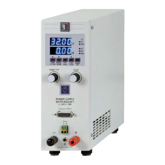
Über das Gerät 3. Gerätebeschreibung 3.1 Front (Bedienung / Ansicht) Beschreibung der Bedien- und Anschlußelemente: Leistungsausgang, gepolt, Sicherheitsbuchsen Die Buchsen können zum Einstecken von 4mm Büschel- steckern oder zum Festklemmen von Gabelkabelschuhen verwendet werden. Achtung! Bei den 1000W und 1500W-Modellen sind die vorde- ren 4mm-Steckanschlüsse der Ausgangsbuchsen nur bis 32A zugelassen! Fernfühlungseingang (Sense), gepolt... -
Seite 8: Weitere Ansichten
Über das Gerät 3.2 Weitere Ansichten Bild 2 1000W / 1500W: © 2006, Elektro-Automatik GmbH & Co. KG Irrtümer und Änderungen vorbehalten Bild 3 Bedienungsanleitung Stand: 10.02.2015 PS 8000 T Serie... -
Seite 9: Lieferumfang
Über das Gerät 3.3 Lieferumfang Bei Leitungen bis 1,5m empfehlen wir: 1 x Netzgerät bis 5A: 0,5mm², bis 10A: 0,75mm² bis 15A: 1,5mm² bis 20A: 2,5mm² 1 x Gedruckte Bedienungsanleitung bei 40A: 6mm², bis 60A: 16mm² 1 x Netzkabel pro Anschlußleitung (Litze, frei verlegt) mindestens zu ver- 4. -
Seite 10: Bedienung Des Gerätes
Nenn werden immer sofort übernommen. Ein dritter Druck auf die Taste beendet den Preset-Modus. Er © 2006, Elektro-Automatik GmbH & Co. KG wird alternativ automatisch beendet, wenn 5s lang kein Sollwert Diese Taste hat zwei Funktionen. Sie wechselt entweder zwi- Irrtümer und Änderungen vorbehalten... -
Seite 11: Taste Lock/Local
Bedienung des Gerätes 6.3 Weitere Bedienelemente b) Bei Ausgang=aus für >3s betätigen --> Geräte-Setup wird angezeigt. Näheres dazu im Abschnitt „8. Geräte-Setup“. Nach- 6.3.1 Taste Standby dem die Geräteeinstellungen getätigt wurden, Betätigung >3s --> Geräte-Setup wird beendet, die Einstellungen gespeichert und die LED über der Taste blinkt dreimal. -
Seite 12: Verhalten Des Gerätes
Ist keine Überspannung mehr vorhanden und soll der Ausgang wieder eingeschaltet werden, muß zuerst der Alarm quittiert werden. Bei manuellem Betrieb geschieht dies mit der Taste © 2006, Elektro-Automatik GmbH & Co. KG Output On, bei analoger Fernsteuerung mit dem Pin „Rem- Irrtümer und Änderungen vorbehalten SB“... -
Seite 13: Netzüber-/Netzunterspannung
Bedienung des Gerätes 7.9 Netzüber-/Netzunterspannung Für alle Schnittstellenkarten folgende Parameter: Die Geräte verfügen über einen Weitbereichseingang. Das Parameter: Standardwert: nodE bedeutet, sie können mit Netzspannungen von etwa 90V bis Wertebereich: 1...30 264V AC betrieben werden. Eingangsspannungen unter 90V Bedeutung: Wählt die Geräteadresse (device node, aus der werden wie ein Ausschalten des Gerätes betrachtet und führen CAN-Terminologie übernommen) für das Gerät. -
Seite 14: Digitale Schnittstellenkarten
USB-Port beinhaltet die komplette Funktionalität 0...5V an den Istwertausgängen. der USB-Schnittstelle IF-U1. Also auch die Verwendung des Einstellung 0-10V: Referenzspannung = 10V, 0...10V Sollwert © 2006, Elektro-Automatik GmbH & Co. KG firmeneigenen, binären Kommunikationsprotokolls. entsprechen 0...100% Nennwert, 0...100% Istwert ensprechen Irrtümer und Änderungen vorbehalten Eine weitere Schnittstellenkarte für Profibusanbindung (IF-PB1) -
Seite 15: Anwendungsbeispiele
Bedienung des Gerätes Bevor Sie beginnen: • Steuern des Gerätes mit externen Sollwerten erfordert die Umschaltung auf Fernsteuerbetrieb mit Pin „Remote“ (5). • Bevor die Hardware, die die analoge Schnittstelle bedienen soll, verbunden wird, sind alle erforderlichen Leitungen zu legen und die Hardware zu prüfen, daß diese keine Span- nungen >12V erzeugen kann. -
Seite 16: Spezifikation Der Anschlüsse
= 20mA +Vcc 11...13V (Bezug: DGND) Kurzschlussfest gegen DGND Output U-Bereich = 0…30V © 2006, Elektro-Automatik GmbH & Co. KG Irrtümer und Änderungen vorbehalten Aus = LOW, U <1V = -1mA bei 5V REM-SB Ausgang aus Ein = HIGH, U >... -
Seite 17: Sonstiges
Bedienung des Gerätes 11. Sonstiges 11.2 Zubehör und Optionen Hinweis: Detaillierte Informationen über Optionen und Zubehör 11.1 Ersatzableitstrommessung nach VDE 0701 sind in separaten Handbüchern bzw. auf Anfrag erhältlich. Die nach DIN VDE 0701-1 durchgeführte Ersatzableitstrom- Folgendes Zubehör ist erhältlich: messung führt unter Umständen zu Ergebnissen, die außerhalb a) USB-zu-Analog-Interface UTA12 der Norm liegen. -
Seite 18: Reihenschaltung
Diese Software und die für das Gerät passende Firmware sind auf der Internetseite des Herstellers zu finden oder werden ggf. auf Anfrage zugeschickt. Das „Update Tool“ führt durch die Aktualisierung, die nahezu automatisch abläuft. © 2006, Elektro-Automatik GmbH & Co. KG Irrtümer und Änderungen vorbehalten Bedienungsanleitung Stand: 10.02.2015... -
Seite 21: Danger To Life
General About Danger to life! Elektro-Automatik GmbH & Co. KG Hazardous voltage Helmholtzstrasse 31-33 The output voltage of some models can rise up to hazar- 41747 Viersen dous levels of >60V Germany All live parts have to be covered. All actions at the out-... - Seite 22 General Page Introduction.....................................23 Technical specifications ................................23 Control panel and display ..............................23 Device specific data ................................24 Device description ..................................25 Front view ..................................25 Other views ..................................26 Scope of delivery ................................27 General....................................27 Prologue / Warning ................................27 Cooling .....................................27 Maintenance / repair .................................27 Installation ....................................27 Visual check..................................27 Mains connection ................................27 DC output terminal ................................27...
-
Seite 23: About The Device
About the device 1. Introduction 2. Technical specifications The laboratory power supplies of the series PS 8000T are 2.1 Control panel and display very compact and rugged devices and incorporate interesting features within small dimensions. Type Apart from standard functions of power supplies the user can define and recall 5 different presets of set values or make use of Display: LED 7 segment display with four... -
Seite 24: Device Specific Data
About the device 2.2 Device specific data Instructions Manual Date: 02-10-2015 PS 8000 T Series... -
Seite 25: Device Description
About the device 3. Device description 3.1 Front view Description of the knobs, buttons and terminals: Power output, safety sockets, poled The sockets can be used to plug 4mm Bueschel plugs or to clamp spade lugs. Attention! With the 1000W and 1500W models, the 4mm front sockets of the DC output connectors are only ap- proved for max. -
Seite 26: Other Views
About the device 3.2 Other views Figure 2 1000W / 1500W: Figure 3 Instructions Manual Date: 02-10-2015 PS 8000 T Series... -
Seite 27: Scope Of Delivery
About the device 3.3 Scope of delivery Attention! 1 x Power supply unit When grounding one of the output poles always check if 1 x Printed user manual one of the poles of the load (eg. electronic load) is also 1 x Mains cord grounded. -
Seite 28: Operating The Device
Operating the device 6. Handling 6.2.2 Pushbutton Memory M1...M5 6.1 The display Figure 4 shows an overview of the LED displays, the LEDs and the control panel. During normal operation, the displays show the actual values of voltage (upper) and current (lower). This pushbutton has two functions: it either selects one of the In preset mode, the displays show the set values of voltage five memory sets with U, I, OVP set values for submission or... -
Seite 29: Pushbutton Lock/Local
Operating the device 6.3 Further control elements b) While the output is off, press button >3s --> device changes to setup mode. For details see section „8. Device setup“. After 6.3.1 Pushbutton Standby all settings are done, press button again for >3s --> device setup will exit, the settings are saved and the LED above the button will flash three times. -
Seite 30: Device Characteristics
Operating the device 7. Device characteristics 7.6 Overtemperature alarms As soon as an overtemperature (OT) alarm occurs due to inter- 7.1 Switching on by power switch nal overheating, the output is switched off and the LED „OT“ is The power switch is located at the rear. After switching the de- lit. -
Seite 31: Mains Undervoltage Or Overvoltage Occurs
Operating the device 7.9 Mains undervoltage or overvoltage occurs For all interface cards applies: The device features an active rectification with PFC and a wide Parameter: Default: nodE range input. This means, it can be operated at input voltages of Settings: 1...30 approx. -
Seite 32: Digital Interface Cards
Operating the device Following setting only for RS232 interface IF-R1: The digital interfaces allow to set voltage and current, as well as the OVP threshold by means of a PC. When changing to remote Parameter: Default: bAud control mode, the device keeps the last set values until they‘re altered. -
Seite 33: Example Applications
Operating the device Please note: • Controlling the device with analogue voltages requires to switch it to remote control with pin „REMOTE“ (5). • Before connecting the application that is used to control the power supply, make sure to wire all leads correctly and check if the application is unable to input voltages higher than specified (max. -
Seite 34: Pin Specification
Operating the device Emulated Master-Slave operation Note True Master-Slave operation is not possible, because the AI Power supplies which are going to be used in parallel connec- does not provide set values outputs. But the actual value out- tion and master-slave control might have an isolated analogue put CMON can be used to control the set values input CSEL interface equipped. -
Seite 35: Miscellaneous
Operating the device 11. Miscellaneous 11.3 Series connection A series connection of power supplies with identical or different 11.1 Accessories and options maximum output voltage and (ideally) identical maximum output current is used to gain a higher total voltage. Note: Details about options and accessories are avaible in seperate user guides. - Seite 38 EA-Elektro-Automatik GmbH & Co. KG Entwicklung - Produktion - Vertrieb Helmholtzstraße 31-33 41747 Viersen Telefon: 02162 / 37 85-0 Telefax: 02162 / 16 230 ea1974@elektroautomatik.de www.elektroautomatik.de...