Elektro-Automatik PS 9000 2U Betriebsanleitung
Inhaltsverzeichnis
Verfügbare Sprachen
Verfügbare Sprachen
Quicklinks
Kapitel
Inhaltsverzeichnis

Verwandte Anleitungen für Elektro-Automatik PS 9000 2U


Inhaltszusammenfassung für Elektro-Automatik PS 9000 2U
- Seite 1 Betriebsanleitung PS 9000 2U DC-Labornetzgerät Doc ID: PS92UDE Revision: 03 Date: 08/2014...
-
Seite 3: Inhaltsverzeichnis
PS 9000 2U Serie INHALT ALLGEMEINES Zu diesem Dokument ........5 2.3.11 Erstinbetriebnahme ........38 1.1.1 Aufbewahrung und Verwendung ....5 2.3.12 Einrichten der Netzwerkverbindung ....38 1.1.2 Urheberschutz (Copyright) ......5 2.3.13 Erneute Inbetriebnahme nach Firmwareup- dates bzw. längerer Nichtbenutzung ...39 1.1.3 Geltungsbereich ..........5 Symbolerläuterungen ........5... - Seite 4 PS 9000 2U Serie ZUBEHÖR UND OPTIONEN Übersicht ............62 SERVICE & SUPPORT Übersicht ............62 Kontaktmöglichkeiten ........62 EA Elektro-Automatik GmbH Telefon: 02162 / 3785-0 www.elektroautomatik.de Seite 4 Helmholtzstr. 31-33 • 41747 Viersen Telefax: 02162 / 16230 ea1974@elektroautomatik.de...
-
Seite 5: Allgemeines
PS 9000 2U Serie Allgemeines Zu diesem Dokument 1.1.1 Aufbewahrung und Verwendung Dieses Dokument ist für den späteren Gebrauch und stets in der Nähe des Gerätes aufzubewahren und dient zur Erläuterung des Gebrauchs des Gerätes. Bei Standortveränderung und/oder Benutzerwechsel ist dieses Dokument mitzuliefern und bestimmungsgemäß... -
Seite 6: Entsorgung Des Gerätes
PS 9000 2U Serie Entsorgung des Gerätes Ein Gerät, das zur Entsorgung vorgesehen ist, muß laut europaweit geltenden Gesetzen und Verordnungen (ElektroG, WEEE) vom Hersteller zurückgenommen und entsorgt werden, sofern der Betreiber des Gerätes oder ein von ihm Beauftragter das nicht selbst erledigt. Unsere Geräte unterliegen diesen Verordnungen und sind dementsprechend mit diesem Symbol gekennzeichnet: Produktschlüssel... -
Seite 7: Sicherheit
PS 9000 2U Serie Sicherheit 1.8.1 Sicherheitshinweise Lebensgefahr - Gefährliche Spannung • Beim Betrieb elektrischer Geräte stehen zwangsweise bestimmte Teile unter teils ge- fährlicher Spannung, mit Ausnahme der 40 V-Modelle gemäß SELV. Daher sind alle spannungsführenden Teile abzudecken! • Alle Arbeiten an den Anschlussklemmen müssen im spannungslosen Zustand des Gerätes erfolgen (DC-Ausgang nicht verbunden mit Last) und dürfen nur von Personen... -
Seite 8: Pflichten Des Betreibers
PS 9000 2U Serie 1.8.3 Pflichten des Betreibers Betreiber ist jede natürliche oder juristische Person, die das Gerät nutzt oder Dritten zur Anwendung überläßt und während der Nutzung für die Sicherheit des Benutzers, des Personals oder Dritter verantwortlich ist. Das Gerät wird im gewerblichen Bereich eingesetzt. Der Betreiber des Gerätes unterliegt daher den gesetzlichen Pflichten zur Arbeitssicherheit. Neben den Warn- und Sicherheitshinweisen in dieser Anleitung müssen die für den... -
Seite 9: Alarmsignale
PS 9000 2U Serie 1.8.5 Alarmsignale Das Gerät bietet diverse Möglichkeiten der Signalisierung von Alarmsituationen, jedoch nicht von Gefahrensitua- tionen. Die Signalisierung kann optisch (auf der Anzeige als Text), akustisch (Piezosummer) oder elektronisch (Pin/Meldeausgang an einer analogen Schnittstelle) erfolgen. Alle diese Alarme bewirken die Abschaltung des DC-Ausgangs. -
Seite 10: Spezifische Technische Daten
PS 9000 2U Serie 1.9.3 Spezifische technische Daten Modell 2U 1000 W PS 9040-40 PS 9080-40 PS 9200-15 AC-Eingang Netzspannung 90...264 V AC 90...264 V AC 90...264 V AC Netzanschluß 1ph,N,PE 1ph,N,PE 1ph,N,PE Netzfrequenz 50/60 Hz 50/60 Hz 50/60 Hz... - Seite 11 PS 9000 2U Serie Modell 2U 1000 W PS 9040-40 PS 9080-40 PS 9200-15 Analoge Schnittstelle Steuereingänge U, I, P U, I, P U, I, P Monitorausgänge U, I U, I U, I DC ein/aus, DC ein/aus, DC ein/aus, Steuersignale Fernst.
- Seite 12 PS 9000 2U Serie Modell 2U 1000 W PS 9360-10 PS 9500-06 PS 9750-04 AC-Eingang Netzspannung 90...264 V AC 90...264 V AC 90...264 V AC Netzanschluß 1ph,N,PE 1ph,N,PE 1ph,N,PE Netzfrequenz 50/60 Hz 50/60 Hz 50/60 Hz Netzsicherung (intern) T16 A...
- Seite 13 PS 9000 2U Serie Modell 2U 1000 W PS 9360-10 PS 9500-06 PS 9750-04 Analoge Schnittstelle Steuereingänge U, I, P U, I, P U, I, P Monitorausgänge U, I U, I U, I DC ein/aus, DC ein/aus, DC ein/aus, Steuersignale Fernst.
- Seite 14 PS 9000 2U Serie Modell 2U 1500 W PS 9040-60 PS 9080-60 PS 9200-25 AC-Eingang Netzspannung 90...264 V AC 90...264 V AC 90...264 V AC - mit zusätzlichem Derating 90...150 V AC 90...150 V AC 90...150 V AC Netzanschluß 1ph,N,PE...
- Seite 15 PS 9000 2U Serie Modell 2U 1500 W PS 9040-60 PS 9080-60 PS 9200-25 Analoge Schnittstelle Steuereingänge U, I, P U, I, P U, I, P Monitorausgänge U, I U, I U, I DC ein/aus, DC ein/aus, DC ein/aus, Steuersignale Fernst.
- Seite 16 PS 9000 2U Serie Modell 2U 1500 W PS 9360-15 PS 9500-10 PS 9750-06 AC-Eingang Netzspannung 90...264 V AC 90...264 V AC 90...264 V AC - mit zusätzlichem Derating 90...150 V AC 90...150 V AC 90...150 V AC Netzanschluß 1ph,N,PE...
- Seite 17 PS 9000 2U Serie Modell 2U 1500 W PS 9360-15 PS 9500-10 PS 9750-06 Analoge Schnittstelle Steuereingänge U, I, P U, I, P U, I, P Monitorausgänge U, I U, I U, I DC ein/aus, DC ein/aus, DC ein/aus, Steuersignale Fernst.
- Seite 18 PS 9000 2U Serie Modell 2U 3000 W PS 9040-120 PS 9080-120 PS 9200-50 AC-Eingang Netzspannung 180...264 V AC 180...264 V AC 180...264 V AC - mit zusätzlichem Derating 180...207 V AC 180...207 V AC 180...207 V AC Netzanschluß 1ph,N,PE...
- Seite 19 PS 9000 2U Serie Modell 2U 3000 W PS 9040-120 PS 9080-120 PS 9200-50 Analoge Schnittstelle Steuereingänge U, I, P U, I, P U, I, P Monitorausgänge U, I U, I U, I DC ein/aus, DC ein/aus, DC ein/aus, Steuersignale Fernst.
- Seite 20 PS 9000 2U Serie Modell 2U 3000 W PS 9360-30 PS 9500-20 PS 9750-12 AC-Eingang Netzspannung 180...264 V AC 180...264 V AC 180...264 V AC - mit zusätzlichem Derating 180...207 V AC 180...207 V AC 180...207 V AC Netzanschluß 1ph,N,PE...
- Seite 21 PS 9000 2U Serie Modell 2U 3000 W PS 9360-30 PS 9500-20 PS 9750-12 Analoge Schnittstelle Steuereingänge U, I, P U, I, P U, I, P Monitorausgänge U, I U, I U, I DC ein/aus, DC ein/aus, DC ein/aus, Steuersignale Fernst.
-
Seite 22: Ansichten
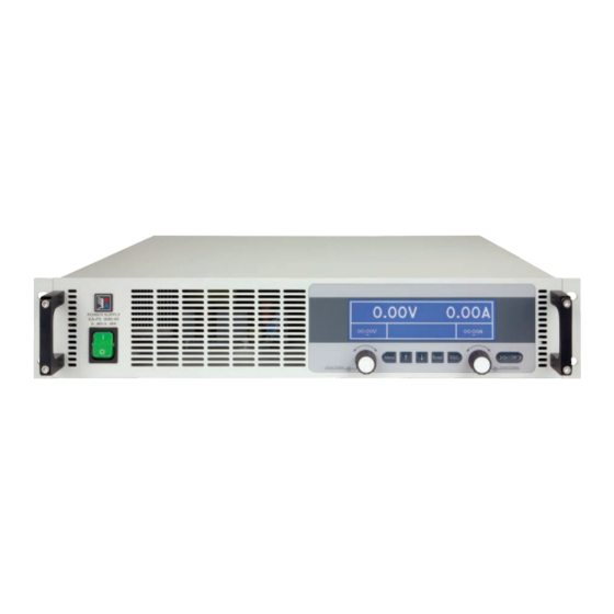
PS 9000 2U Serie 1.9.4 Ansichten Bild 1 - Vorderseite Bild 2 - Rückseite EA Elektro-Automatik GmbH Telefon: 02162 / 3785-0 www.elektroautomatik.de Seite 22 Helmholtzstr. 31-33 • 41747 Viersen Telefax: 02162 / 16230 ea1974@elektroautomatik.de... - Seite 23 PS 9000 2U Serie EA Elektro-Automatik GmbH Telefon: 02162 / 3785-0 www.elektroautomatik.de Seite 23 Helmholtzstr. 31-33 • 41747 Viersen Telefax: 02162 / 16230 ea1974@elektroautomatik.de...
- Seite 24 PS 9000 2U Serie Bild 5 - Ansicht von oben, mit DC-Abdeckung (Klemme Typ 1) EA Elektro-Automatik GmbH Telefon: 02162 / 3785-0 www.elektroautomatik.de Seite 24 Helmholtzstr. 31-33 • 41747 Viersen Telefax: 02162 / 16230 ea1974@elektroautomatik.de...
-
Seite 25: Drehknopf Links, Mit Tastfunktion
PS 9000 2U Serie Bild 6 - Bedienfeld Übersicht der Bedienelemente am Bedienfeld Für eine genaue Erläuterung siehe Abschnitt „1.10.6. Die Bedieneinheit (HMI)“. Anzeige Dient zur Anzeige von Sollwerten, Menüs, Zuständen, sowie Istwerten und Status. Drehknopf links, mit Tastfunktion Drehen: Einstellen von allen Sollwerten, die auf die Ausgangsspannung des Gerätes bezogen sind Drücken: Dezimalstelle eines einzustellenden Wertes wechseln, um diese durch Drehen dann zu verändern... -
Seite 26: Aufbau Und Funktion
1.10.1 Allgemeine Beschreibung Die elektronischen Hochleistungsnetzgeräte der Serie PS 9000 2U sind durch ihre recht kompakten 19“-Einschub- gehäuse mit 2 Höheneinheiten (2HE, 2U) besonders für Prüfsysteme und Industriesteuerungen geeignet. Für die Fernsteuerung per PC oder SPS verfügt das Gerät serienmäßig über eine rückwärtige USB-B-Schnittstelle, eine Ethernetschnittstelle, sowie eine Analogschnittstelle. -
Seite 27: Lieferumfang
PS 9000 2U Serie 1.10.3 Lieferumfang 1 x Netzgerät 1 x Gedruckte Betriebsanleitung 1 x Stecker für Share-Bus (aufgesteckt oder beiliegend) 1 x Stecker für Fernfühlung (aufgesteckt oder beiliegend) 1 x USB-Kabel 1,8 m 1 x CD „Drivers & Tools“... -
Seite 28: Die Bedieneinheit (Hmi)
PS 9000 2U Serie 1.10.6 Die Bedieneinheit (HMI) HMI steht für Human Machine Interface, auf deutsch Mensch-Maschine-Schnittstelle, und besteht hier aus einer Anzeige, zwei Drehknöpfen mit Tastfunktion und sechs Drucktasten. 1.10.6.1 Anzeige Die grafische Anzeige ist in mehrere Bereiche aufgeteilt. Im Normalfall werden im oberen Teil die Istwerte und im unteren Teil die Sollwerte und Statusinformationen angezeigt:... -
Seite 29: Tastfunktion Der Drehknöpfe
PS 9000 2U Serie Dieses Feld zeigt weiterhin diverse Statustexte an: Anzeige Beschreibung Gesperrt Das HMI ist gesperrt Fern Das Gerät befindet sich in Fernsteuerung durch... Analog ...die eingebaute Analogschnittstelle ...die eingebaute USB-Schnittstelle Ethernet ...die eingebaute Ethernet/LAN-Schnittstelle Lokal Das Gerät ist durch Benutzereingabe explizit gegen Fernsteuerung gesperrt worden Alarm: OT usw. -
Seite 30: Usb-Port (Rückseite)
PS 9000 2U Serie 1.10.7 USB-Port (Rückseite) Der USB-Port Typ B auf der Rückseite des Gerätes dient zur Kommunikation mit dem Gerät, sowie zur Firmwareaktualisierung. Über das mitgelieferte USB-Kabel kann das Gerät mit einem PC verbunden werden (USB 2.0, USB 3.0). Der Treiber wird auf CD mitgeliefert bzw. -
Seite 31: 1.10.10 Share-Bus-Anschluß
Parallelschaltung von bis zu 10 gleichartigen Geräten eine gleichmäßigen Laststromaufteilung zu erreichen. Folgende Netzgeräteserien und elektronische Lastserien sind kompatibel: • PS 9000 2U/3U (neu ab 2014) • PSI 9000 2U/3U (neu ab 2014) • ELR 9000 1.10.11 Sense-Anschluß (Fernfühlung) -
Seite 32: Installation & Inbetriebnahme
PS 9000 2U Serie Installation & Inbetriebnahme Transport und Lagerung 2.1.1 Transport • Die Griffe an der Vorderseite des Gerätes dienen nicht zum Tragen! • Das Gerät sollte aufgrund seines Gewichts und je nach Modell möglichst nicht per Hand trans- portiert werden bzw. -
Seite 33: Vorbereitung
2.3.2 Vorbereitung Für den netzseitigen Anschluß des Netzgerätes der Serie PS 9000 2U ist ein 3poliges Netzkabel von 2 m Länge im Lieferumfang enthalten. Soll das Gerät anders verkabelt werden, so ist sicherzustellen, daß der Querschnitt der verwendeten Zuleitung mindestens 3x 2,5 mm² (wie beim Netzkabel) beträgt. -
Seite 34: Anschluß An Das Stromnetz (Ac)
PS 9000 2U Serie 2.3.4 Anschluß an das Stromnetz (AC) • Der Anschluß des Gerätes mittels des mitgelieferten Netzkabels kann an jeder Wandsteckdose bzw. Steckdosenverteilung erfolgen, die über einen Schutzkontakt verfügt und für mindestens 16 A ausgelegt ist. • Bei Verwendung einer Steckdosenverteilung muß die Gesamtleistung aller angeschlossenen Geräte beachtet werden, so daß... -
Seite 35: Kabelzuführung Und Plastikabdeckung
PS 9000 2U Serie 2.3.5.2 Kabelzuführung und Plastikabdeckung Für die DC-Anschlußklemme wird eine Plastikabdeckung (siehe oben) als Berührungsschutz mitgeliefert. Diese sollte immer installiert sein. Beide Abdeckungen werden mit Rändelmuttern an der Anschlußklemme fixiert. Im Gegensatz zum Typ 2 sind in der Abdeckung Typ 1 Ausbrüche (oben, unten) vorhanden, die nach Bedarf ausge- brochen werden können, um Zuleitungen aus verschiedenen Richtungen zu verlegen. -
Seite 36: Anschluß Der Fernfühlung
PS 9000 2U Serie 2.3.7 Anschluß der Fernfühlung Um Spannungsabfälle auf den DC-Zuleitungen bis zu einem gewissen Grad kompensieren zu können, bietet das Gerät einen Fernfühlungsanschluß, der mit der Last verbunden werden kann. Das Gerät erkennt den Fernfüh- lungsbetrieb automatisch und „fühlt“ die Ausgangsspannung (nur im CV-Betrieb möglich) dann an der Last, statt am eigenen DC-Ausgang. -
Seite 37: Anschließen Des „Share-Bus
PS 9000 2U Serie 2.3.8 Anschließen des „Share-Bus“ Die rückseitig am Gerät befindliche Klemme „Share-Bus“ dient bei Parallelbetrieb mehrerer Netzgeräte zur Stromsymmetrierung und Ausregelung bei Funktionsgeneratorbetrieb (Sinus usw.). Der Share-Bus sollte daher verbunden werden. Weitere Information siehe auch „3.8.1 Parallelschaltung mit Share Bus“ auf Seite 56. Für die Verschaltung des Share-Bus‘... -
Seite 38: Erstinbetriebnahme
PS 9000 2U Serie 2.3.11 Erstinbetriebnahme Bei der allerersten Inbetriebnahme nach dem Erwerb des Gerätes und der Erstinstallation sind zusätzliche Maß- nahmen zu ergreifen: • Überprüfen Sie die von Ihnen verwendeten Anschlußkabel für AC und DC auf ausreichenden Querschnitt! • Überprüfen Sie die werkseitigen Einstellungen bezüglich Sollwerte, Sicherheits- und Überwachungsfunktionen sowie Kommunikation daraufhin, daß... -
Seite 39: Erneute Inbetriebnahme Nach Firmwareupdates Bzw. Längerer Nichtbenutzung
PS 9000 2U Serie 2.3.13 Erneute Inbetriebnahme nach Firmwareupdates bzw. längerer Nichtbenutzung Bei der erneuten Inbetriebnahme nach einer Firmwareaktualisierung, Rückerhalt des Gerätes nach einer Reparatur oder nach Positions- bzw. Konfigurationsveränderungen der Umgebung des Gerätes sind ähnliche Maßnahmen zu ergreifen wie bei einer Erstinbetriebnahme. Siehe daher auch „2.3.11. Erstinbetriebnahme“. Erst nach erfolgreicher Überprüfung des Gerätes nach den gelisteten Punkten darf es wie gewohnt in Betrieb genommen werden. -
Seite 40: Bedienung Und Verwendung
PS 9000 2U Serie Bedienung und Verwendung Personenschutz • Um Sicherheit bei der Benutzung des Gerätes zu gewährleisten, darf das Gerät nur von Per- sonen bedient werden, die über die erforderlichen Sicherheitsmaßnahmen im Umgang mit gefährlichen elektrischen Spannungen unterrichtet worden sind • Bei Geräten, die eine berührungsgefährliche Spannung erzeugen können oder an diese... -
Seite 41: Leistungsregelung / Konstantleistung / Leistungsbegrenzung
PS 9000 2U Serie 3.2.3 Leistungsregelung / Konstantleistung / Leistungsbegrenzung Leistungsregelung, auch Leistungsbegrenzung oder Konstantleistung (kurz: CP) genannt, hält die DC-Ausgangsleistung bei Netzgeräten konstant auf dem einge- stellten Wert, wenn der in den Verbraucher fließende Strom in Zusammenhang mit der eingestellten Ausgangsspannung und dem Widerstand des Verbrauchers nach P = U * I bzw. -
Seite 42: Überstrom (Overcurrent)
PS 9000 2U Serie 3.2.4.4 Überstrom (Overcurrent) Ein Überstromalarm (kurz: OCP) führt zur Abschaltung des DC-Ausgangs und kann auftreten , wenn • der aus dem DC-Ausgang fließende Ausgangsstrom die eingestellte OCP-Schwelle überschreitet Diese Schutzfunktion dient nicht dem Schutz des Netzgerätes, sondern dem Schutz der angeschlossenen Last, damit diese nicht durch zu hohen Strom beschädigt oder bei einem Defekt, der überhöhten Strom zur Folge hat, nicht irreparabel zerstört wird. - Seite 43 PS 9000 2U Serie EA Elektro-Automatik GmbH Telefon: 02162 / 3785-0 www.elektroautomatik.de Seite 43 Helmholtzstr. 31-33 • 41747 Viersen Telefax: 02162 / 16230 ea1974@elektroautomatik.de...
-
Seite 44: Beschreibung
PS 9000 2U Serie 3.3.3.1 Menü „Allgemeine Einstellungen“ Element S. Beschreibung Fernsteuerung erlauben Bei Wahl „Nein“ kann das Gerät weder über eine der digitalen, noch über die analoge Schnittstelle fernbedient werden. Der Status, daß die Fernsteuerung gesperrt ist, wird im Statusfeld der Hauptseite mit „Lokal“ angezeigt. Siehe auch Abschnitt 1.10.6.1. - Seite 45 PS 9000 2U Serie 3.3.3.7 Menü „Kommunikation“ Hier werden Einstellungen zum auf der Rückseite des Gerätes befindlichen Ethernet/LAN-Port (Rückseite) getrof- fen. Der USB-Port benötigt keine Einstellungen. Das Gerät hat bei Auslieferung oder nach einer Zurücksetzung folgende Standard-Netzwerkparameter im Untermenü „IP-Einstellungen 1“: • DHCP: aus • IP: 192.168.0.2 • Subnetzmaske: 255.255.255.0 • Gateway: 192.168.0.1 • Port: 5025...
-
Seite 46: Einstellgrenzen (Limits)
PS 9000 2U Serie 3.3.3.8 Menü „HMI-Einstellung“ Diese Einstellungen beziehen sich ausschließlich auf die Bedieneinheit (HMI) und deren Anzeige. In der Tabelle unten werden der Einfachheit halber alle einstellbaren Elemente aufgelistet, egal in welchem der Untermenüs des HMI-Setups diese einsortiert sind:... -
Seite 47: Soll- Und Istwertanzeige Wechseln
PS 9000 2U Serie 3.3.5 Soll- und Istwertanzeige wechseln Standardmäßig zeigt das PS 9000 Gerät in der linken Hälfte der Anzeige den Spannungssollwert und Spannungs- istwert, sowie in der rechten Hälfte den Stromsollwert und Stromistwert. Damit Sie alternativ den Leistungssollwert ständig zur Verfügung haben, kann der Anzeigemodus der Soll- und Istwerte umgeschaltet werden. -
Seite 48: Das Schnellmenü
PS 9000 2U Serie 3.3.7 Das Schnellmenü Das Schnellmenü bietet bei eingeschaltetem Ausgang vier Menüpunkte zur schnellen Auswahl, die über das nor- male Menü auch zu erreichen wäre, aber nur bei ausgeschaltetem Ausgang. Das Schnellmenü kann über Taste erreicht werden und sieht so aus: Naviganion wie sonst auch mit den Pfeiltasten Über das Schnellmenü... -
Seite 49: Fernsteuerung
PS 9000 2U Serie Fernsteuerung 3.4.1 Allgemeines Fernsteuerung ist grundsätzlich über die eingebaute analoge oder eine der eingebauten digitalen Schnittstellen (USB, Ethernet/LAN) möglich. Wichtig ist dabei, daß entweder nur die analoge oder eine digitale im Eingriff sein kann. Das bedeutet, wenn man zum Beispiel versuchen würde bei aktiver analoger Fernsteuerung (Pin Remote = LOW und Status „Fern Analog“... -
Seite 50: Fernsteuerung Über Analogschnittstelle (As)
PS 9000 2U Serie 3.4.4 Fernsteuerung über Analogschnittstelle (AS) 3.4.4.1 Allgemeines Die fest eingebaute, bis 1500 V DC galvanische getrennte, 15-polige analoge Schnittstelle (kurz: AS) befindet sich auf der Rückseite des Gerätes und bietet folgende Möglichkeiten: • Fernsteuerung von Strom, Spannung und Leistung • Fernüberwachung Status (CC/CP, CV) • Fernüberwachung Alarme (OT, OVP) • Fernüberwachung der Istwerte • Ferngesteuertes Ein-/Ausschalten des DC-Ausganges... -
Seite 51: Spezifikation Der Analogschnittstelle
PS 9000 2U Serie 3.4.4.3 Spezifikation der Analogschnittstelle Pin Name Typ* Bezeichnung Pegel Elektrische Eigenschaften 0…10 V bzw. 0...5 V ent- VSEL Sollwert Spannung Genauigkeit < 0,2% sprechen 0..100% von U Nenn 0…10 V bzw. 0...5 V ent- Eingangsimpedanz R >40 k...100 k... -
Seite 52: Prinzipschaltbilder Der Pins
PS 9000 2U Serie 3.4.4.5 Prinzipschaltbilder der Pins Digitaler Eingang (DI) Analoger Eingang (AI) Die innere Beschaltung gibt vor, daß ein Hochohmiger Eingang (Impedanz: möglichst niederohmiger Schalter zu >40 k...100 kΩ) einer OP-Schaltung. V~0.5 verwenden ist (Relaiskontakt, Schalter, Schütz o.ä.), um das Signal sauber nach DGND zu schalten. -
Seite 53: Alarme Und Überwachung
PS 9000 2U Serie Alarme und Überwachung 3.5.1 Begriffsdefinition Grundsätzlich ist bei Gerätealarmen (siehe „3.2.4. Alarmzustände“) nur von gemeldeten Zuständen wie Über- spannung oder Übertemperatur die Rede, die im Zusammenhang mit teils einstellbaren Überwachungsgrenzen auftreten können. Diese Alarme werden immer mindestens als ablesbare Meldung in der Anzeige, sowie also abfragbarer Status bei der digitalen Fernsteuerung bzw. -
Seite 54: Bedieneinheit (Hmi) Sperren
PS 9000 2U Serie ► So konfigurieren Sie die Gerätealarme OVP, OCP und OPP Schalten Sie den DC-Ausgang aus und betätigen Sie Taste , um das Menü aufzurufen. Navigieren Sie im Menü zu „Einstellungen“ und betätigen Sie . Dann weiter zu „Schutz-Einstellungen“... -
Seite 55: Nutzerprofile Laden Und Speichern
PS 9000 2U Serie Nutzerprofile laden und speichern Das Menü „Profile“ dient zur Auswahl eines Profils, um es zu Laden, bzw. zum Wechsel zwischen einem Stan- dardprofil und fünf Nutzerprofilen. Ein Profil ist eine Sammlung aller Einstellungen und aller Sollwerte. Bei Auslie- ferung des Gerätes bzw. nach einem Zurücksetzungsvorgangs haben alle sechs Profile dieselben Einstellungen und sämtliche Sollwerte sind auf 0. Werden vom Anwender dann Einstellungen getroffen und Werte verändert, so geschieht das in einem Arbeitsprofil, das auch über das Ausschalten hinweg gespeichert wird. Dieses Arbeitsprofil kann in eins der fünf Nutzerprofile gespeichert bzw. aus diesen fünf Nutzerprofilen oder aus dem Standardprofil heraus geladen werden. Das Standardprofil selbst kann nur geladen werden. Wenn das Arbeitsprofil aus dem Standardprofil heraus geladen und überschrieben wird, entspricht das dem Zurücksetzen des Gerätes. Der Sinn von Profilen ist es, z. B. einen Satz von Sollwerten, Einstellgrenzen und Überwachungsgrenzen schnell zu laden, ohne diese alle jeweils immer neu einstellen zu müssen. Da sämtliche Einstellungen zum HMI mit im Profil gespeichert werden, also auch die Sprache, wäre beim Wechsel von einem Profil zum anderen auch ein... -
Seite 56: Weitere Anwendungen
PS 9000 2U Serie Weitere Anwendungen 3.8.1 Parallelschaltung mit Share Bus Mehrere Geräte gleicher Art und gleichen Modells können zu einer Parallelschaltung verbunden werden, um eine höhere Gesamtleistung zu erzielen. Dabei werden alle Netzgeräte an ihren DC-Ausgängen verbunden, sowie zusätzlich über den Share-Bus. Der Share-Bus dient zur Ausregelung des Ausgangsspannung und daher auch des Ausgangsstromes, damit eine gleichmäßige Lastaufteilung erreicht wird. -
Seite 57: Alarm- Und Andere Problemsituationen
PS 9000 2U Serie 3.8.1.5 Alarm- und andere Problemsituationen Beim Share-Bus-Betrieb können, durch die Verbindung mehrerer Geräte und deren Zusammenarbeit, zusätzliche Problemsituationen entstehen, die beim Betrieb einzelner Geräte nicht auftreten würden. Es wurden für solche Fälle folgende Festlegungen getroffen: • Falls ein oder mehrere Slave-Geräte AC-seitig ausfallen (ausgeschaltet am Netzschalter, Netzunterspannung) arbeiten sie nach der Wiederkehr automatisch wieder als Slaves weiter. -
Seite 58: Instandhaltung & Wartung
PS 9000 2U Serie Instandhaltung & Wartung Wartung / Reinigung Die Gerät erfordern keine Wartung. Reinigung kann, jenachdem in welcher Umgebung sie betrieben werden, frü- her oder später für die internen Lüfter nötig sein. Diese dienen zur Kühlung der internen Komponenten, die durch die zwangsweise entstehende, jedoch geringe Verlustleistung erhitzt werden. -
Seite 59: Firmwareaktualisierung (Updates)
PS 9000 2U Serie Firmwareaktualisierung (Updates) 4.3.1 Aktualisierung der Bedieneinheit (HMI) Die Bedieneinheit (HMI) kann nur über einen PC und eine kleine Hilfssoftware, ein „Update Tool“, aktualisiert wer- den. Dieses Tool ist entweder auf der beiliegenden CD oder auf der Webseite des Geräteherstellers zu finden bzw. auf Anfrage erhältlich, ebenso wie dazu benötigte Firmware-Datei. Weitere Instruktion sind in der Dokumentation des Update Tools zu finden. -
Seite 60: Gerät Abgleichen (Nachjustierung)
PS 9000 2U Serie Gerät abgleichen (Nachjustierung) 4.4.1 Einleitung Die Geräte der Serie PS 9000 verfügen über eine Nachjustierungsfunktion, die im Rahmen einer Kalibrierung dazu dient, Abweichungen zwischen den Stellwerten und tatsächlichen Werten bis zu einem gewissen Grad zu kompensieren. Gründe, die eine Nachjustierung der Gerätestellwerte nötig machen, gibt es einige: Bauteilalterung, Bauteilverschleiß, extreme Umgebungsbedingungen, häufige Benutzung. - Seite 61 PS 9000 2U Serie ► So gleichen Sie die Spannung ab Spannungsmeßgerät am DC-Ausgang anschließen. Die Last auf etwas unter 5% des Nennstromes des Netzgerätes, hier z. B. 5 A, einstellen. In der Anzeige des PS in das wechseln, dann Taste bestätigen.
-
Seite 62: Service & Support
PS 9000 2U Serie Zum Schluß kann noch über den Menüpunkt „Abgleichdatum eingeben“ das Datum des Abgleichs im Format JJJJ / MM / TT eingegeben und mit Taste übernommen, oder auch nur abgerufen werden. Danach sollten die Abgleichwerte unbedingt noch über den Menüpunkt „Speichern und beenden“ + speichert werden. - Seite 64 EA-Elektro-Automatik GmbH & Co. KG Entwicklung - Produktion - Vertrieb Helmholtzstraße 31-33 41747 Viersen Telefon: 02162 / 37 85-0 Telefax: 02162 / 16 230 ea1974@elektroautomatik.de www.elektroautomatik.de...
- Seite 128 EA-Elektro-Automatik GmbH & Co. KG Entwicklung - Produktion - Vertrieb Helmholtzstraße 31-33 41747 Viersen Telefon: 02162 / 37 85-0 Telefax: 02162 / 16 230 ea1974@elektroautomatik.de www.elektroautomatik.de...