Elektro-Automatik PS 8000 2U Bedienungsanleitung
Vorschau ausblenden
Andere Handbücher für PS 8000 2U:
- Bedienungsanleitung (48 Seiten) ,
- Bedienungsanleitung (40 Seiten)
Inhaltsverzeichnis
Werbung
Verfügbare Sprachen
Verfügbare Sprachen
Quicklinks
Bedienungsanleitung
PS 8000 2U
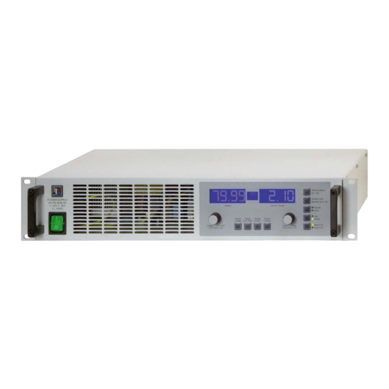
Laboratory Power Supply
Abbildung zeigt Standardgerät 2HE / Picture shows standard 2U version
Instruction Manual
PS 8032-20 2U:
PS 8065-10 2U:
PS 8160-05 2U:
PS 8080-40 2U:
PS 8080-60 2U:
PS 8080-120 2U:
PS 8160-60 2U:
09 230 130
PS 8360-15 2U:
09 230 131
PS 8360-30 2U:
09 230 132
PS 8720-15 2U:
09 230 133
PS 8040-60 2U:
09 230 134
PS 8040-120 2U:
09 230 135
09 230 136
09 230 137
09 230 138
09 230 139
09 230 144
09 230 145
Werbung
Kapitel
Inhaltsverzeichnis

Verwandte Anleitungen für Elektro-Automatik PS 8000 2U


Inhaltszusammenfassung für Elektro-Automatik PS 8000 2U
- Seite 1 Bedienungsanleitung Instruction Manual PS 8000 2U Laboratory Power Supply Abbildung zeigt Standardgerät 2HE / Picture shows standard 2U version PS 8032-20 2U: 09 230 130 PS 8360-15 2U: 09 230 137 PS 8065-10 2U: 09 230 131 PS 8360-30 2U:...
- Seite 3 Allgemeines Impressum Lebensgefahr! Elektro-Automatik GmbH & Co. KG Gefährliche Ausgangsspannung Helmholtzstrasse 31-33 Bei manchen Modelle kann die Ausgangsspannung be- 41747 Viersen rührungsgefährliche Werte von >60V erreichen! Germany Alle spannungsführenden Teile sind abzudecken. Alle Telefon: 02162 / 37850 Arbeiten an den Anschlussklemmen müssen im span- nungslosen Zustand des Gerätes erfolgen (Netzschalter...
-
Seite 4: Inhaltsverzeichnis
10.1 Allgemeines ..................................19 10.2 Anwendungsbeispiele..............................19 10.3 Spezifikation der Anschlüsse ............................21 11. Weitere Anwendungen ................................22 11.1 Funktionen der Klemme System Bus ..........................22 © 2006, Elektro-Automatik GmbH & Co. KG Irrtümer und Änderungen vorbehalten 11.1.1 Reihenschaltung als Master-Slave ...........................22 11.1.2 Parallelschaltung im Share-Bus-Betrieb ........................23 11.1.3... -
Seite 5: Über Das Gerät
Über das Gerät Einleitung Technische Daten Die Labornetzgeräte der Serie PS 8000 2U sind durch ihr Bedien- und Anzeigeeinheit 19“-Einschubgehäuse besonders für Prüfsysteme und Indu- striesteuerungen geeignet. Ausführung Über die gängigen Funktionen von Netzgeräten hinaus können 5 verschiedene Sollwertvorgabesätze eingestellt, gespeichert und... -
Seite 6: Gerätespezifische Daten
EN 60950, EN 61326, EN 55022 Klasse B Überspannungskategorie Schutzklasse Verschmutzungsgrad Betriebshöhe <2000m Reihenschaltung 600V max. Reihenschaltungsspannung © 2006, Elektro-Automatik GmbH & Co. KG nein Master-Slave Irrtümer und Änderungen vorbehalten Parallelschaltung max. Parallelschaltungsspannung 720V ja, über Sharebus Master-Slave Analoge Programmierung Eingangsbereich 0…5V oder 0…10V, umschaltbar... - Seite 7 * Bezogen auf den Nennwert definiert die Genauigkeit die maximale Abweichung zwischen Sollwert und Istwert. Beispiel: ein 80V-Gerät hat min. 0,2% Spannungsgenauigkeit, das sind 160mV. Bei einem Sollwert von 5V dürfte der Istwert also max. 160mV abweichen, sprich er dürfte 4,84V...5,16V betragen. Bedienungsanleitung Stand: 09.02.2012 PS 8000 2U Serie...
- Seite 8 EN 60950, EN 61326, EN 55022 Klasse B Überspannungskategorie Schutzklasse Verschmutzungsgrad <2000m Betriebshöhe Reihenschaltung 600V max. Reihenschaltungsspannung © 2006, Elektro-Automatik GmbH & Co. KG Master-Slave nein Irrtümer und Änderungen vorbehalten Parallelschaltung 720V max. Parallelschaltungsspannung Master-Slave ja, über Sharebus Analoge Programmierung Eingangsbereich 0…5V oder 0…10V, umschaltbar...
-
Seite 9: Gerätebeschreibung
Über das Gerät Gerätebeschreibung Ansichten Bedienungsanleitung Stand: 09.02.2012 PS 8000 2U Serie... -
Seite 10: Lieferumfang
H - Leistungsausgang, M8-Schrauben 8 - Masse J - Netzsicherungen (Wert siehe „2. Technische Daten“) K - Netzanschluß (siehe Abschnitt 5.3) © 2006, Elektro-Automatik GmbH & Co. KG L - Bedienfeld ZH-Option Irrtümer und Änderungen vorbehalten Lieferumfang 1 x Netzgerät 1 x Gedruckte Bedienungsanleitung(en) 1 x Netzkabel (nur bei 2HE-Geräten) -
Seite 11: Allgemeines Zum Gerät
Das Gerät kann optional mit einer Steckkarte ausgestattet wer- den. Der Anschluß hierfür befindet sich auf der Rückseite des Gerätes. Weitere Informationen über die Erweiterungskarten, hier auch Schnittstellenkarten genannt, sind im Abschnitt „9. Digitale Schnittstellenkarten“ zu finden. Bedienungsanleitung Stand: 09.02.2012 PS 8000 2U Serie... -
Seite 12: Bedienung
Sollwertsatz gehörigen Spannungssollwert Fine - Feineinstellmodus für beide Drehknöpfe aktiv umgeschaltet, aber der hier eingestellte Wert wird nicht sofort © 2006, Elektro-Automatik GmbH & Co. KG übernommen. Die Anzeige sieht dann so aus: PF - Power fail (Netzunterspannungsfehler, ab Firmware 6) Irrtümer und Änderungen vorbehalten... -
Seite 13: Bedienung Des Gerätes
Hinweistext wird stattdessen angezeigt. Bei Geräten ab 1000W ändert sich die Darstellung rechts in: Mit dem Drehknopf rechts (Current / Power) kann der Sollwert von 0...100% P eingestellt werden. Der eingestellte Wert Nenn wird sofort übernommen. Bedienungsanleitung Stand: 09.02.2012 PS 8000 2U Serie... -
Seite 14: Taste Memory Select M1-M5
Ausgang aus, einen oder mehrere Sollwertsätze anwählen, eingeschaltetem Ausgang wird die aktuelle Regelungsart CC, © 2006, Elektro-Automatik GmbH & Co. KG Sollwerte einstellen, dann Druck auf die Taste >3s --> alle CV oder CP (nur bei Geräten mit Leistungsregelung, ab 1kW) Irrtümer und Änderungen vorbehalten... -
Seite 15: Weitere Bedienelemente
Nennwert Grob Fein 0,2V 0,01V 0,05A 0,001A 0,25V 0,01V 0,1A 0,01A 0,5V 0,01V 0,1A 0,01A 0,5V 0,01V 0,2A 0,01A 160V 0,1V 0,2A 0,01A 360V 0,1V 0,5A 0,01A 720V 0,1V 0,5A 0,01A 120A 0,1A Bedienungsanleitung Stand: 09.02.2012 PS 8000 2U Serie... -
Seite 16: Verhalten Des Gerätes
Leistung begrenzt, also Leistungsregelbetrieb. Anzeige „OV“ und das Signal am Pin „OVP“ erlöschen dann. © 2006, Elektro-Automatik GmbH & Co. KG Damit sinken Ausgangsstrom und -spannung auf die sich Ist der Alarm weiterhin vorhanden, kann der Ausgang nicht Irrtümer und Änderungen vorbehalten... -
Seite 17: Fernfühlungsbetrieb
Adresse nur einmal vergeben werden. restwelligkeit oder andere, unerwünschte Effekte bewirken. Ohmsche Lasten verhalten sich dagegen nahezu neutral. Das Verhalten der Lasten ist daher stets im Betriebskonzept der Anwendung zu berücksichtigen. Bild 6. Verdrahtung Fernfühlung (Sense) Bedienungsanleitung Stand: 09.02.2012 PS 8000 2U Serie... -
Seite 18: Digitale Schnittstellenkarten
Spannungssteuerung durch Vorgabe von Spannungssollwerten möglich, wenn die anderen Sollwerte Das andere System ist mit drei CAN-IDs kompatibel zu z. © 2006, Elektro-Automatik GmbH & Co. KG unverändert blieben. Irrtümer und Änderungen vorbehalten B. Software der Firma Vector Informatik und ermöglicht die Verwendung von sog. -
Seite 19: Die Analogschnittstelle
„aus“ vorgibt, es sein denn, LOCAL-Modus ist aktiv. Dieser sperrt alle Schnittstellen vor Zugriff auf das Gerät. Siehe auch „6.2.7 Taste Local“. • Die Massen der AS sind bezogen auf Minus Ausgang. Bild 8 Bedienungsanleitung Stand: 09.02.2012 PS 8000 2U Serie... - Seite 20 10kOhm benutzt werden. Der Leistungssollwert wird hier, für Geräte mit Leistungseinstel- lung, fest auf VREF gelegt und somit mit 100% vorgegeben. oder © 2006, Elektro-Automatik GmbH & Co. KG Irrtümer und Änderungen vorbehalten Bedienungsanleitung Stand: 09.02.2012 PS 8000 2U Serie...
-
Seite 21: Spezifikation Der Anschlüsse
AI = Analoger Eingang, AO = Analoger Ausgang, DI = Digitaler Eingang, DO = Digitaler Ausgang, POT = Potential Interne Vcc, ca. 14,3V Nur bei Modellen ab 1kW Nennleistung Ausfall Netz oder PFC (wird gemeldet ab Firmware 6.01) Bedienungsanleitung Stand: 09.02.2012 PS 8000 2U Serie... -
Seite 22: Weitere Anwendungen
Potential zu erden, in dem Fall Minus (-) vom henschaltung. Ein Gerät ist dabei stets der Master des nächsten Master. Gerätes (Slaves) und so weiter. © 2006, Elektro-Automatik GmbH & Co. KG Irrtümer und Änderungen vorbehalten Bild 9. Reihenschaltung Master-Slave Bedienungsanleitung Stand: 09.02.2012... -
Seite 23: Parallelschaltung Im Share-Bus-Betrieb
Parallelschaltung. Der Strom-Istwert wird nicht automatisch summiert und muß daher vom Anwender mit der Anzahl der Geräte multipliziert werden. Alternativ können natürlich auch alle Einzelgeräte analog oder digital überwacht werden, um alle Istwerte zu erfassen. Bild 10. Parallel-Share-Bus-Betrieb Bedienungsanleitung Stand: 09.02.2012 PS 8000 2U Serie... -
Seite 24: Gemischte Verschaltungen
Busteilnehmern verbunden und durch Device Node und RID (siehe „Geräte-Setup) integriert werden können. Bei GPIB besteht lediglich die Beschränkung auf max. 15 Geräte am Bus. © 2006, Elektro-Automatik GmbH & Co. KG Irrtümer und Änderungen vorbehalten Bedienungsanleitung Stand: 09.02.2012... -
Seite 25: Sonstiges
„…Bei Geräten mit zweipoliger Abschaltung und symmetrischer auf Anfrage zugeschickt. Das „Update Tool“ führt durch die kapazitiver Schaltung darf der Meßwert bei diesem Verfahren Aktualisierung, die nahezu automatisch abläuft. halbiert werden...“ Grafische Verdeutlichung der symmetrischen Schaltung: Bedienungsanleitung Stand: 09.02.2012 PS 8000 2U Serie... -
Seite 27: Danger To Life
General About Danger to life! Elektro-Automatik GmbH & Co. KG Hazardous voltage Helmholtzstrasse 31-33 The output voltage of some models can rise up to ha- 41747 Viersen zardous levels of >60V Germany All live parts have to be covered. All actions at the out-... - Seite 28 10.1 General ....................................43 10.2 Application examples...............................43 10.3 Pin specification................................45 11. Other applications ...................................46 11.1 Functions of terminal System Bus ...........................46 © 2006, Elektro-Automatik GmbH & Co. KG Irrtümer und Änderungen vorbehalten 11.1.1 Series connection in Master-Slave mode .........................46 11.1.2 Parallel connection (Share Bus) ..........................47 11.1.3...
-
Seite 29: About The Device
About the device Introduction Technical specifications The laboratory power supplies of the series PS 8000 2U are Control panel and display ideally suited for test systems and industrial control facilities by their 19“ draw-out case. Apart from standard functions of power supplies the user can... -
Seite 30: Technical Specifications
Overvoltage class Protection class Pollution degree Operation altitude < 2000m Series connection 600V max. series connection voltage © 2006, Elektro-Automatik GmbH & Co. KG Master-Slave Irrtümer und Änderungen vorbehalten Parallel connection 720V max. parallel connection voltage yes, via Share bus Master-Slave... - Seite 31 Example: a 80V model has min. 0.2% voltage accuracy. This is 160mV. When setting a voltage of 5V and with an allowed maximum deviation of 160mV, the resulting actual value could be between 4.84V and 5.16V. Instruction Manual Date: 02-09-2012 PS 8000 2U Series...
- Seite 32 Overvoltage class Protection class Pollution degree Operation altitude < 2000m Series connection max. series connection voltage 600V © 2006, Elektro-Automatik GmbH & Co. KG Master-Slave Irrtümer und Änderungen vorbehalten Parallel connection 720V max. parallel connection voltage Master-Slave yes, via Share bus...
-
Seite 33: Device Description
About the device Device description Views Instruction Manual Date: 02-09-2012 PS 8000 2U Series... -
Seite 34: Scope Of Delivery
8 - Ground J - Input fuses (for value see „2. Technical specifications“) K - Power input terminal (see section 5.3) © 2006, Elektro-Automatik GmbH & Co. KG Irrtümer und Änderungen vorbehalten L - Control panel of ZH option Scope of delivery... -
Seite 35: General
The unit can be equipped with an optional interface card. The slot to insert the card is located at the rear side. Further infor- mation about the interface cards can be found in section „9. Digital interface cards“. Instruction Manual Date: 02-09-2012 PS 8000 2U Series... -
Seite 36: Handling
(6) - Preset buttons: Switching to set value display (7) - Rotary knob left: Set value adjustment of U, UVL, OVP, as © 2006, Elektro-Automatik GmbH & Co. KG well as parameters in the device setup Irrtümer und Änderungen vorbehalten... -
Seite 37: Operating The Device
A second push leaves the preset mode instantly or it ends automatically, if no preset button is pushed or any set value is altered within 5 seconds. The button might be locked by the condition LOCK. See 6.2.8. Instruction Manual Date: 02-09-2012 PS 8000 2U Series... -
Seite 38: Pushbutton Memory Select M1-M5
1kW) in the status area in the middle of the display. none is submitted to the output. The output remains off, the The button might be locked by the condition LOCK. See 6.2.8. © 2006, Elektro-Automatik GmbH & Co. KG memory mode exits after saving. Irrtümer und Änderungen vorbehalten... -
Seite 39: Other Control Elements
Nom. val. Coarse Fine 0.2V 0.01V 0.05A 0.001A 0.25V 0.01V 0.1A 0.01A 0.5V 0.01V 0.1A 0.01A 0.5V 0.01V 0.2A 0.01A 160V 0.1V 0.2A 0.01A 360V 0.1V 0.5A 0.01A 720V 0.1V 0.5A 0.01A 120A 0.1A Instruction Manual Date: 02-09-2012 PS 8000 2U Series... -
Seite 40: Device Characteristics
The status of an OV alarm has priority over the status of an © 2006, Elektro-Automatik GmbH & Co. KG power limit and the device would change from constant power OT alarm and will overwrite the status text „OT“... -
Seite 41: Remote Sense Operation
Ohmic loads are almost 100% neutral. It is recommen- ded to consider the load situation when planning applications. Figure 6. Wiring the sense Instruction Manual Date: 02-09-2012 PS 8000 2U Series... -
Seite 42: Digital Interface Cards
CAN IDs, plus a broadcast ID (if used). Set values given by the digital interface (except GPIB) are al- © 2006, Elektro-Automatik GmbH & Co. KG ways percentage and correspond at 100% (hex: 0x6400), resp. Irrtümer und Änderungen vorbehalten at 110% (hex: 0x6E00) for the OVP threshold, to the nominal values of the device. -
Seite 43: Analogue Interface
, except LOCAL mode is active. This mode locks all interface from access to the device. Also see „6.2.7 Pushbutton Local“. • The grounds of the analogue interface are related to minus output. Figure 8 Instruction Manual Date: 02-09-2012 PS 8000 2U Series... - Seite 44 VREF output, potentiometers with at least 10kOhm have to be used. The power set value is here, for models with power regulation feature, tied to VREF and thus 100%. © 2006, Elektro-Automatik GmbH & Co. KG Irrtümer und Änderungen vorbehalten Instruction Manual Date: 02-09-2012...
-
Seite 45: Pin Specification
AI = Analogue input, AO = Analogue output, DI = Digital input, DO = Digital output, POT = Potential Internal Vcc, approx. 14.3V Only with models from 1kW Power fail = input failure or PFC (reported only since firmware 6.01) Instruction Manual Date: 02-09-2012 PS 8000 2U Series... -
Seite 46: Other Applications
(-) output of the master. output current will define the maximum current of the system. © 2006, Elektro-Automatik GmbH & Co. KG Irrtümer und Änderungen vorbehalten Figure 9. Series connection in Master-Slave... -
Seite 47: Parallel Connection (Share Bus)
(only applicable if all have the same no- minal output current) or all units will have to be read seperately. Figure 10. Parallel connection with Share Bus Instruction Manual Date: 02-09-2012 PS 8000 2U Series... -
Seite 48: Mixed Connections
With GPIB there is a limitation of max. 15 units on one bus, con- trolled by a GPIB master. Multiple GPIB masters can be installed in a PC in order to increase the number of addressable units. © 2006, Elektro-Automatik GmbH & Co. KG Irrtümer und Änderungen vorbehalten Instruction Manual... -
Seite 49: Miscellaneous
The update tool and the particular firmware file for your device are obtainable from the website of the device manufacturer, or are mailed upod request. The update too will guide the user through the semi-automatic update process. Instruction Manual Date: 02-09-2012 PS 8000 2U Series... - Seite 52 EA-Elektro-Automatik GmbH & Co. KG Entwicklung - Produktion - Vertrieb Development - Production - Sales Helmholtzstraße 31-33 41747 Viersen Germany Telefon: +49 (0)2162 / 37 85-0 Telefax: +49 (0)2162 / 16 230 ea1974@elektroautomatik.de www.elektroautomatik.de...