KEB COMBICONTROL C5 Compact Betriebsanleitung
Inhaltsverzeichnis
Verfügbare Sprachen
Verfügbare Sprachen
Quicklinks
Inhaltsverzeichnis

Verwandte Anleitungen für KEB COMBICONTROL C5 Compact


Inhaltszusammenfassung für KEB COMBICONTROL C5 Compact
- Seite 1 COMBICONTROL C5 Compact Betriebsanleitung GB Instruction Manual Mat.No. Rev. 00C5C1B-K140...
- Seite 2 Die in dieser Anleitung aufgeführten Sicherheits- und Warnhinweise erheben keinen Anspruch auf Vollständigkeit. Die Betriebsanleitung und die darin enthaltenen Informationen wurden mit der gebotenen Sorgfalt zusammengestellt, KEB übernimmt jedoch keine Gewähr für Druckfehler oder andere Fehler oder daraus entstehende Schäden.
-
Seite 3: Inhaltsverzeichnis
Inhalt Beschreibung des Gerätes..............4 Verwendungszweck ....................4 Aufbau ........................4 1.3 CE-Zertifizierung ....................4 1.4 Geräteidentifikation ....................4 Technische Daten ....................5 Zubehör ........................6 Funktionsbeschreibung ................7 Echtzeituhr ......................7 HSP5/485-Schnittstellen zu den Umrichter-/Servoachsen .........7 2.2.1 Ansicht der Umrichterschnittstellen X1A...X1D für die Achsen 1..4 ......8 2.2.2 Belegung der HSP5/485-Schnittstellen ..............8 2.2.3 HSP5-Operator mit Schraubklemme (00F5060-9001) ..........9 2.2.4 HSP5-Operator mit RJ45-Buchse (00F5060-9002) ..........9... -
Seite 4: Beschreibung Des Gerätes
Verwendungszweck KEB COMBICONTROL C5 ist eine programmierbare Steuerung mit direkter Anbindung an bis zu vier KEB Frequenzumrichter-/ Servoachsen der Baureihe F5. Die Verbindung zu den Achsen ist als HSP5/485 ausgeführt. Mit dieser schnellen, störsicheren Verbindung können alle Achsen mittels eines preiswerten Operators direkt und synchron betrieben werden. Dabei sind Zykluszeiten bis herab zu einer Millisekunde realisierbar. -
Seite 5: Technische Daten
IEC 61131-2 Typ 1 Achsenschnittstelle HSP5/485 Stecker RJ-45, 8-polig, geschirmt Kabel Cat5, max. 100 m Geschwindigkeit 38,4…250 kBaud Verwendung Anschluss an einen KEB F5 Umrichter/Servo, Prozessdatenübertragung, Kommunikations- kanal Ethernetschnittstellen IEEE802.3 10/100BaseTx 2-Port Switch Stecker RJ-45, 8-polig, geschirmt Geschwindigkeit 10/100 MBaud... -
Seite 6: Zubehör
COMBICONTROL Verwendung Verbindung zu CoDeSys (Programmiersystem, Debugging, Visualisierung). Verbindung zu COMBIVIS (Steuerungs- und Achseneinstellung, Scope). Verbindung zu beliebigen Teilnehmern (So- cket-APi). Serielle Schnittstelle DIN66019II, RS232, RS485 voll-/halbduplex Stecker D-Sub 9 female Geschwindigkeit 9,6…115,2 kBaud Verwendung Verbindung zu COMBIVIS (Steuerungs- und Achseneinstellung, Scope). -
Seite 7: Funktionsbeschreibung
HSP5/485-Schnittstellen zu den Umrichter-/Servoachsen Bis zu vier KEB COMBIVERT F5 können über die Klemmen X1A bis X1D angeschlossen werden. Die Verbindung erfolgt über störsichere RS485-Leitungen, die bis zu 100 m lang sein können. Dabei wird ein geschirmtes Standardkabel mit RJ-45 Stecker auf der Steu- erungsseite und entsprechendem Operator auf dem Umrichter/Servo verwendet. -
Seite 8: Ansicht Der Umrichterschnittstellen X1A
COMBICONTROL 2.2.1 Ansicht der Umrichterschnittstellen X1A...X1D für die Achsen 1..4 X1B (Achse 2) —— —— X1A (Achse 1) X1D (Achse 4) —— —— X1C (Achse 3) 2.2.2 Belegung der HSP5/485-Schnittstellen X1A…D Name Beschreibung Buchse (Draufsicht) TXD+ Sendesignal+ TXD- Sendesignal- Bezugspotential RXD+ Empfangssignal+ RXD- Empfangssignal-... -
Seite 9: Hsp5-Operator Mit Schraubklemme (00F5060-9001)
COMBICONTROL 2.2.3 HSP5-Operator mit Schraubklemme (00F5060-9001) X6E Name Beschreibung TxD- Sendesignal - TxD+ Sendesignal + RxD- Empfangssignal - An der Klemme VCC darf keine RxD+ Empfangssignal + Leitung angeschlossen werden. EnTxD- Handshake Sendesignal - Die hohe Spannung kann die EnTxD+ Handshake Sendesignal + Schnittstelle in der Steuerung EnRxD- Handshake Empfangssignal- zerstören. -
Seite 10: Verbindungskabel Hsp5-Schnittstelle - Operator
COMBICONTROL 2.2.5 Verbindungskabel HSP5-Schnittstelle - Operator Schraubanschluss: Color siehe unten C5 PCC Signal TxD+ TxD- GND RxD+ RxD- GND EnTxD+ EnTxD- X1A…H Operator Signal RxD+ RxD- GND TxD+ TxD- GND EnRxD+ EnRxD- Color siehe unten RJ45 Anschluss: Color siehe unten C5 PCC Signal TxD+ TxD- GND RxD+ RxD- GND EnTxD+ EnTxD- X1A...H... -
Seite 11: Spannungsversorgung Und Digitale Ein-/Ausgänge
COMBICONTROL Spannungsversorgung und digitale Ein-/Ausgänge Bild 2.3 Buchse X2 Spannungsversorgung Digitale Ein- und Ausgänge Digitaleingang 0 Digitaleingang 1 + Spannungseingänge (UM) (intern verbunden) Digitaleingang 2 Digitaleingang 3 Digitalausgang 0 Digitalausgang 1 - Spannungseingänge (UM) (intern verbunden) Digitalausgang 2 Digitalausgang 3 + Spannungseingang (US) - Spannungseingang (US) 2.3.1 Montage der Anschlusslitzen... -
Seite 12: Spannungsversorgung Der Steuerung
COMBICONTROL 3. Kabel in die runde Öffnung stecken, sodass keine Litzen von außen zu sehen sind. 4. Schraubendreher entfernen und prüfen ob Kabel fest sitzt. 2.3.2 Spannungsversorgung der Steuerung Die Spannung zur Versorgung der Steuerung (US) erfolgt über die Klemmen X2.9 und X2.10 gemäß... -
Seite 13: Digitale Eingänge (X2.11
COMBICONTROL Bild 2.3.3 Spannungseingang zur Versorgung der Ein- und Ausgänge X2.1...4 U = 18…30 V DC ±0 % F2 = 6,3 A Typ gG X2.5...8 2.3.4 Digitale Eingänge (X2.11…14) Die digitalen Eingänge sind potentialfrei zur Steuerspannung US. 4 Digitaleingänge 0...3 %IX0.0…%IX0.3 %IW0 Zustand der digitalen Eingänge 0…3 nicht belegt... -
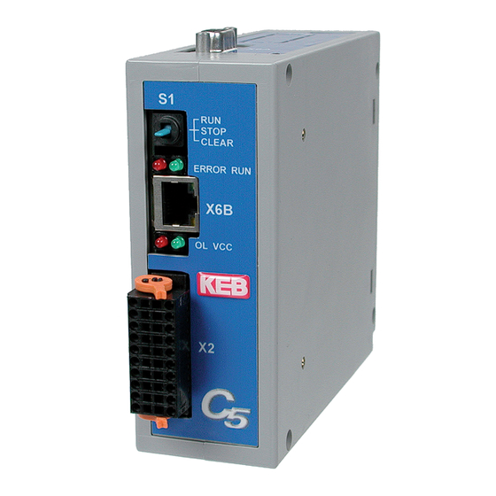
Seite 14: Das Bedienteil
COMBICONTROL Das Bedienteil Ansicht Front Name Funktion Zusatz Ansicht unten Multifunktionsschalter/ -taster RUN-LED grün ERROR ERROR-LED Überlastung Versorgungsspannung (US) grün Serielle Schnittstelle COMBIVIS Ethernet-Schnittstelle COMBIVIS/ CoDeSys Ethernet-Schnittstelle X1A…D Achsschnittstellen Serielle Schnittstelle (X6A) Die Buchse X6A ist eine serielle RS232/485-Schnittstelle. Sie dient zur Verbindung der Steu- erung mit einem PC oder anderen Bedieneinheiten über das Protokoll DIN66019II. -
Seite 15: Ethernet-Schnittstelle (X6B/X6C)
COMBICONTROL Ethernet-Schnittstelle (X6B/X6C) Die standardisierte 10/100 BaseTx Schnittstelle unterstützt die Protokolle TCP/IP und UDP/ IP. Die beiden Schnittstellen sind intern als Switch verbunden. Folgende Ports haben dabei diese Funktionen: Der CoDeSys-Port ist standardmäßig auf 1200 eingestellt. Der Port kann über den Parameter Et.03 verändert werden. -
Seite 16: Multifunktionschalter/-Taster S1
COMBICONTROL Multifunktionschalter/-taster S1 Der Multifunktionsschalter/-taster ist wie folgt aufgebaut: run (Schalter) stop/reset clear (Taster) Der Taster S1 ist mit folgenden Funktionen belegt: Aktion Funktion Stop --> Run Programm wird gestartet Run --> Stop Programm wird gestoppt, alle Variablen werden zurückgesetzt (Reset Warm) Stop -->... -
Seite 17: Software
Die Achssteuerung wird mit dem Programmiersystem CoDeSys der Firma 3S-Software pro- grammiert (www.3s-software.com). Diese Programmiersoftware ist frei im Internet erhältlich. Als Zubehör ist ein Target Information File (TNF) von KEB für die Steuerung verfügbar, das alle nötigen Hardwarefestlegungen enthält. Weiterhin enthalten ist eine Bibliothek mit Firm- ware-Funktionsbausteinen zum Zugriff auf die Peripherie (Achsen, Echtzeituhr, Schalter, LEDs , Dateisystem). -
Seite 18: Parameterbeschreibung
COMBICONTROL Parameterbeschreibung 3.3.1 Laufzeit- und Fehlerüberwachung Die ru-Parameter dienen zur Überwachnung des Programablaufes. ru.00 Status Adresse 0200h Progammstatus no prog kein Progamm geladen prog OK Programm geladen prog corrupt Programm-Checksummenfehler Steuerungsstatus Programm läuft stop Programm gestoppt breakpoint Programm steht auf Überwachungspunkt Fehlerstatus err_cyctime Die eingestellte Zykluszeit wurde überschritten... -
Seite 19: Ethernetparameter
COMBICONTROL 3.3.2 Ethernetparameter Die folgenden Parameter enthalten die Werte, die zur Kommunikation über die Ethernet- Schnittstelle benötigt werden. et.00 MAC Adresse Adresse 0300h Die MAC-Adresse (Media Access Control) wird aus 6 Byte gebildet. Die ersten drei Bytes enthalten den Herstellercode (00-08-FA). Angezeigt werden hier nur die untersten 4 Bytes „FAxxxxxx“. -
Seite 20: Gateway Adresse
COMBICONTROL Datenport Passwort et.09 Adresse 0309h Dieser Parameter legt das Schreibschutzpasswort für den COMBIVIS Datenport fest. Die Programmierung des Passwortes erfolgt nur über die serielle Schnittstelle, dann ist für einen Schreibzugriff über den Datenport hier dieses Passwortes erneut einzugeben. Bei gesperrtem Datenportschreibzugriff wird die Fehlermeldung „Operation nicht möglich“... -
Seite 21: Prozessabbild
COMBICONTROL Sekunden rc.01 Adresse 0401h Dieser Parameter zeigt die Sekunden im Bereich von 0...59 an. Schreiben auf diesen Parmeter stellt die Sekunden ein. Datum rc.02 Adresse 0402h Dieser Parameter zeigt das Datum im Format TT-MM an. Schreiben auf diesen Parmeter stellt das Datum ein. -
Seite 22: Bedienoberfläche
COMBICONTROL pi.06 Achs-Eingangsdaten 3 Adresse 0506h Zeigt den Wert des 3.Prozess-Eingangsdatums (16 Bit) der Achsen an. Satz 0 ist für die Daten der Achse 1, Satz 1 für die Achse 2, etc. pi.07 Achs-Ausgangsdaten 3 Adresse 0507h Zeigt den Wert des 3.Prozess-Ausgangsdatums (16 Bit) der Achsen an. Satz 0 ist für die Daten der Achse 1, Satz 1 für die Achse 2, etc. -
Seite 23: Systemparameter
COMBICONTROL ud.05 Rx-Fehlerzähler Adresse 0805h Dieser Parameter zählt die Empfangsfehler bei der Kommunikation mit den Achsen. Da- bei zeigt Satz 0 die Fehler der Achse 1, Satz 1 die der Achse 2 usw. an. ud.06 Tx-Fehlerzähler Adresse 0806h Dieser Parameter zählt die Fehler beim Senden zu den einzelnen Achsen. Dabei zeigt Satz 0 die Fehler der Achse 1, Satz 1 die der Achse 2 usw. -
Seite 24: Debugging
Dieser Parameter legt die Feldbus-Geräteadresse fest. sy.07 Baudrate 66019II Adresse 0007h Mit diesem Parameter wird die Baudrate für das KEB DIN 66019II Protokoll eingestellt. sy.10 Adresse 000Ah Anzeige des Gerätetyps. Die folgenden Parameter dienen zum Betrieb des Inverter-Scope-Teils von COMBIVIS. -
Seite 25: Systemvariablen
COMBICONTROL Systemvariablen Folgende Systemvariablen sind im SPS-Programm verfügbar: SYSAXISMODE Zeigt die über den Funktionsbaustein ‚tSetModes‘ eingestellte Achsenbetriebsarten an. SYSERRORAXIS Zeigt die ausgefallenen überwachten oder zyklisch/synchron betriebenen Achsen an. Bei Ausfall einer Achse wird die rote Fehler-LED am Bedienteil eingeschaltet und der Event „excpt_axis_error“... - Seite 26 Notizen D - 26...
- Seite 50 Notes GB - 26...
- Seite 51 Notes GB - 27...
- Seite 52 +39 02 33535311 • fax: +39 02 33500790 net: www.keb.it • mail: kebitalia@keb.it KEB Power Transmission Technology (Shanghai) Co.,Ltd. No. 435 QianPu Road, Songjiang East Industrial Zone, KEB Japan Ltd. CHN-201611 Shanghai, P.R. China 15–16, 2–Chome, Takanawa Minato-ku fon: +86 21 37746688 • fax: +86 21 37746600 J–Tokyo 108-0074...