Sentiotec Pro D Montage- Und Gebrauchsanweisungen
Saunasteuerung
Inhaltsverzeichnis
Verfügbare Sprachen
Verfügbare Sprachen
Quicklinks
Sauna control unit
Pro D
INSTRUCTIONS FOR INSTALLATION AND USE
English
Pro D2
Pro D2 white
Pro D2i
Pro D2i white
Pro D3
D3 white
Pro D3i
D3i white
Version 12/20
1-041-288/PRO-D2
1-041-290/PRO-D2W
1-041-291/PRO-D2I
1-041-292/PRO-D2IW
1-041-293/PRO-D3
1-041-294/PRO-D3W
1-041-295/PRO-D3I
1-041-296/PRO-D2IW
Ident-Nr. 1-041-284
EN
DE
FR
IT
NL
SV
FI
RU
Kapitel
Inhaltsverzeichnis
Fehlerbehebung

Verwandte Anleitungen für Sentiotec Pro D


Inhaltszusammenfassung für Sentiotec Pro D
-
Seite 71: Saunasteuerung
Saunasteuerung Pro D MONTAGE- UND GEBRAUCHSANWEISUNG Deutsch Pro D2 1-041-288 / PRO-D2 Pro D2 white 1-041-290 / PRO-D2W Pro D2i 1-041-291 / PRO-D2I Pro D2i white 1-041-292 / PRO-D2IW Pro D3 1-041-293 / PRO-D3 Pro D3 white 1-041-294 / PRO-D3W... - Seite 72 Inhaltsverzeichnis 1. Zu dieser Anleitung 2. Wichtige Hinweise zu Ihrer Sicherheit 2.1. Bestimmungsgemäßer Gebrauch 2.2. Sicherheitshinweise für den Monteur 2.3. Sicherheitshinweise für den Anwender 3. Produktbeschreibung 3.1. Lieferumfang 3.2. Optionales Zubehör 3.3. Produktfunktionen 3.4. Sauna-Betriebsarten 3.5. Fühler-Betriebsarten 4. Montage 4.1. Leistungsteil montieren 4.2.
- Seite 73 Bedienteil Pro D2i 9.3. Bedienteil Pro D3 9.4. Bedienteil Pro D3i 9.5. Zusatzausgang Bedienteil Pro D (optional) 9.6. Leistungsteil 10. Bedienung 10.1. Licht am Leistungsteil einschalten (Reinigungsbeleuchtung) 10.2. Leistungsteil einschalten 10.3. Bedienteil aktivieren 10.4. Zusatzausgang Bedienteil Pro D (optional) 10.5. Sauna-Betrieb starten...
- Seite 74 10.6. Sauna-Betrieb ausschalten 10.7. Kombi-Betrieb starten (nur Pro D3 / Pro D3i) 10.8. Kombi-Betrieb ausschalten (nur Pro D3 / Pro D3i) 10.9. Zusatzausgang starten (nur Pro D2i / Pro D3i) 10.10. Zusatzausgang ausschalten (nur Pro D2i / Pro D3i) 10.11. Licht einschalten 10.12.
- Seite 75 14. Entsorgung 15. Problemlösung 15.1. Fehlermeldungen 15.2. Wassermangelanzeige (nur Pro D3 / Pro D3i) 15.3. Sicherungen 16. Technische Daten 16.1. Leistungsteil 16.2. Bedienteil Pro D2 / Pro D2i / Pro D3 / Pro D3i 16.3. Zusatzausgang Bedienteil Pro D (optional)
-
Seite 76: Zu Dieser Anleitung
Nähe der Saunasteuerung auf. So können Sie jederzeit Informationen zu Ihrer Sicherheit und zur Bedienung nachlesen. Sie finden diese Montage- und Gebrauchsanweisung auch im Download- bereich unserer Webseite auf www.sentiotec.com/downloads. Symbole in Warnhinweisen In dieser Montage- und Gebrauchsanweisung ist vor Tätigkeiten, von denen eine Gefahr ausgeht, ein Warnhinweis angebracht. -
Seite 77: Wichtige Hinweise Zu Ihrer Sicherheit
Die Saunasteuerungen der Pro D Serie dienen ausschließlich zum Steuern und Regeln der Funktionen gemäß den technischen Daten. Die Saunasteuerungen der Pro D Serie dürfen nur zum Steuern und Regeln eines Saunaofens, der die Abdeckprüfung nach Absatz 19.101 der EN 60335-2-53 besteht, verwendet werden. Erfüllt der Ofen diese Voraussetzung nicht, muss eine entsprechende Sicher- heitsvorkehrung getroffen werden (z. Bsp.: Sicherheitsabschaltung... -
Seite 78: Sicherheitshinweise Für Den Monteur
Montage- und Gebrauchsanweisung S. 8/37 2.2. Sicherheitshinweise für den Monteur ● Die Montage darf nur durch eine Elektrofachkraft oder eine ver- gleichsweise qualifizierte Person ausgeführt werden. ● Arbeiten an der Saunasteuerung dürfen nur im spannungsfreien Zustand durchgeführt werden. ● Es ist bauseits eine allpolige Trennvorrichtung mit voller Abschal- tung entsprechend der Überspannungskategorie III vorzusehen. -
Seite 79: Sicherheitshinweise Für Den Anwender
Montage- und Gebrauchsanweisung S. 9/37 2.3. Sicherheitshinweise für den Anwender ● Die Saunasteuerung darf nicht von Kindern unter 8 Jahren ver- wendet werden. ● Die Saunasteuerung darf von Kindern über 8 Jahren, von Perso- nen mit verringerten psychischen, sensorischen oder mentalen Fähigkeiten und von Personen mit Mangel an Erfahrung und Wissen unter folgenden Bedingungen verwendet werden: –... -
Seite 80: Produktbeschreibung
● Bedienteil Pro D3i (1-1040-173 / PRO-D3I-CU) ● Bedienteil Pro D3i white (1-1-040-173 / PRO-D3IW-CU) ● Zusatzausgang Bedienteil Pro D (1-040-174 / PRO-DA-CU) ● Zusatzausgang Bedienteil Pro D white (1-040-175 / PRO-DAW-CU) ● Pro D BUS-Converter RS485 (1-045-317 / PRO-D-CON) ● Webserver ProNet (1-017-521 / PRO-NET) ●... -
Seite 81: Produktfunktionen
Montage- und Gebrauchsanweisung S. 11/37 3.3. Produktfunktionen Pro D2 / Pro D2 white Die Saunasteuerung Pro D2 / Pro D2 white verfügt über folgende Funktionen: ● Regeln von Saunaöfen mit einer Heizleistung bis 10,5 kW im Temperaturbe- reich von 30 °C bis 110 °C. ●... - Seite 82 Montage- und Gebrauchsanweisung S. 12/37 Pro D2i / Pro D2i white Funktionsumfang wie Pro D2 / Pro D2 white jedoch zusätzlich: ● Zusatzausgang Wahlweise Dimmen (bis 500 W), Schalten (bis 3,5 kW) oder Regeln der Kabinentemperatur über den Zusatzausgang. Zusatzausgang hat keine Übertemperatursicherung. Deshalb dürfen am Zusatzausgang nur eigensichere Geräte betrieben werden.
- Seite 83 Montage- und Gebrauchsanweisung S. 13/37 Pro D3 / Pro D3 white Die Saunasteuerung Pro D3 / Pro D3 white verfügt über folgende Funktionen: ● Regeln von Kombi-Saunaöfen mit einer Heizleistung bis 10,5 kW und einer- Verdampferleistung bis 3,5 kW im Temperaturbereich von 30 °C bis 110 °C und einem Feuchtebereich von 0 bis 100 %.
- Seite 84 ● 1-027-785 / ECO-350-R, 1-027-784 / ECO-350-G, 1-027-788 / ECO-500-R, 1-027-787 / ECO-500-G, 1-027-790 / ECO-750-R – Wenn an den Zusatzausgang eine der folgenden Infrarot-Wärmeplatten Pro D2 (white) Pro D2i (white) Pro D3 (white) Pro D3i (white) Abb.1 Funktionsübersicht Pro D...
-
Seite 85: Sauna-Betriebsarten
Montage- und Gebrauchsanweisung S. 15/37 angeschlossen wird, muss der Folienfühler 1-014-445 / P-ISX-FF verwendet werden und im Technikermenü aktiviert werden (siehe „Folienfühler aktivieren/deaktivieren (nur Pro D2i/Pro D3i)“ auf Seite 39): ● 1-028-348 / IR-WP-100, 1-028-343 / IR-WP-175, 1-028-784 / IR-WP-390, 1-028-938 / IR-WP-510 ●... -
Seite 86: Fühler-Betriebsarten
Montage- und Gebrauchsanweisung S. 16/37 3.5. Fühler-Betriebsarten Die Saunasteuerungen der Pro D Serie können mit einem oder mit zwei Fühlern betrieben werden. Als zweiter Fühler kann ein Temperaturfühler (Bankfühler F2) oder ein Feuchte-Temperaturfühler (FTS2, nur Pro D3 / Pro D3i) verwendet werden. - Seite 87 Montage- und Gebrauchsanweisung S. 17/37 Zweifühler-Betrieb mit Bankfühler (F2) Der Zwei-Fühlerbetrieb muss mittels Funktionswahlschalter aktiviert werden (siehe „Zwei-Fühlerbetrieb aktivieren“ auf Seite 36). Im Zwei-Fühlerbetrieb mit Bankfühler wird ein zweiter Temperaturfühler (Bank- fühler) oberhalb der hinteren Saunabank montiert. Die Saunasteuerung zeigt als Ist-Temperatur jene Temperatur an, die vom Bankfühler gemessen wird.
-
Seite 88: Montage
Montageanweisung – nur für Fachpersonal S. 18/37 4. Montage 4.1. Leistungsteil montieren ACHTUNG! Schäden am Gerät Die Saunasteuerung ist spritzwassergeschützt, trotzdem kann direkter Kontakt mit Wasser das Gerät beschädigen. ● Montieren Sie die Saunasteuerung an einem trockenen Ort, an dem eine maximale Luftfeuchte von 95% nicht überschritten wird. - Seite 89 Montageanweisung – nur für Fachpersonal S. 19/37 Zur Montage der Saunasteuerung führen Sie folgende Schritte durch: 1. Drehen Sie zwei Kreuzschlitzschrauben (16 mm) in ca. 1,70 m Höhe bis zu einem Abstand von 7 mm in die Saunawand ein. Die beiden Schrauben müssen einen Abstand von 145 mm zueinander haben (siehe Abb.2).
-
Seite 90: Bedienteil Montieren
Montageanweisung – nur für Fachpersonal S. 20/37 4.2. Bedienteil montieren Das Bedienteil 2 wird an der Kabinenwand im maximalen Abstand von 10 Metern zum Leistungsteil 1 montiert (siehe Abb.4). Für die Montage wird beispielsweise eine handelsübliche Stichsäge benötigt um die Ausnehmung für das Bedienteil zu schneiden. Das Bedienteil kann sowohl in der Kabine als auch außerhalb der Kabine montiert werden. - Seite 91 1. Mit beispielsweise einer Stichsäge die Ausnehmung 70 x 65 oder 60 x 48 mm schneiden (siehe Abb.5 und Abb.6). 2. Leitungsführungen für die Verbindungsleitungen vorsehen. 3. Gehäuse durch die Bohrung mit den 4 oder 2 beiligenden Holzschrauben an die Kabinenwand schrauben. Abb.5 Montage Bedienteil Pro D Abb.6 Montage Zusatzausgang Bedienteil (optional)
- Seite 92 Montageanweisung – nur für Fachpersonal S. 22/37 4. Die Frontplatte des Bedienteils wird mit leichtem Druck in das Gehäuse eingesteckt. Achten Sie darauf, dass der untere Befestigungshaken spürbar einrastet. Abb.7 Montage Bedienteil 5. Verbinden Sie den 4-poligen Stecker mit der RJ11 Buchse des Bedienteils.
-
Seite 93: Ofenfühler F1 Mit Übertemperatur-Sicherung Montieren
Montageanweisung – nur für Fachpersonal S. 23/37 4.3. Ofenfühler F1 mit Übertemperatur-Sicherung montieren Beachten Sie bei der Montage des Ofenfühlers folgende Punkte: ● Der Ofenfühler ist an der Ofen-Rückwand oberhalb der Mitte des Saunaofens zu montieren. Dabei ist ein Abstand von zirka 15 cm zur Kabinendecke ein- zuhalten. -
Seite 94: Bankfühler F2 Montieren (Optional)
Montageanweisung – nur für Fachpersonal S. 24/37 4.4. Bankfühler F2 montieren (optional) Der Bankfühler ist an der Kabinenwand oberhalb der hinteren Sitzbank zu mon- tieren. Dabei ist ein Abstand von zirka 15 cm zur Kabinendecke einzuhalten. Zur Montage des Bankfühlers führen Sie folgende Schritte durch: 1. -
Seite 95: Folien-Fühler Montieren (Optional, Nur Pro D2I / Pro D3I) Montieren
Montageanweisung – nur für Fachpersonal S. 25/37 4.6. Folien-Fühler montieren (optional, nur Pro D2i / Pro D3i) montieren Wenn an den Zusatzausgang eine der folgenden Infrarot-Wärmeplatten ange- schlossen wird, muss der Folienfühler 1-014-445 / P-ISX-FF verwendet werden: ● 1-028-348 / IR-WP-100 ●... -
Seite 96: Elektrischer Anschluss
Montageanweisung – nur für Fachpersonal S. 26/37 5. Elektrischer Anschluss ACHTUNG! Schäden am Gerät ● Die Saunasteuerung darf nur zum Steuern und Regeln von 3 Heizkreisen mit einer Heizleistung von max. 3,5 kW pro Heizkreis eingesetzt werden. Die maximale Verdampferleistung (nur Pro D3 / Pro D3i) beträgt 3,5 kW. Die ma- ximale Leistung des Zusatzausgangs (nur Pro D2i / Pro D3i) beträgt 3,5 kW. -
Seite 97: Versorgungsleitung, Ofen Und Verdampfer Anschließen
Montageanweisung – nur für Fachpersonal S. 27/37 Beachten Sie beim elektrischen Anschluss der Saunasteuerung folgende Punkte: ● Die Montage darf nur durch eine Elektrofachkraft oder eine vergleichsweise qualifizierte Person ausgeführt werden. Bitte beachten Sie, dass im Falle eines Garantieanspruches eine Kopie der Rechnung des ausführenden Elektrofachbetriebes vorzulegen ist. ●... -
Seite 98: Bedienteil Anschließen
4 in den Anschlussbereich für Kleinspannung 1. 2. Stecken Sie den Stecker des RJ-10-Kabels in die Anschlussbuchse h. Die Saunasteuerungen der Pro D Serie ermöglichen den Betrieb von bis zu 2 Pro D Bedienteilen und einem Zusatzausgang Bedienteil, an einem Leistungsteil. -
Seite 99: Licht Anschließen
Montageanweisung – nur für Fachpersonal S. 29/37 5.3. Licht anschließen 1. Führen Sie die Lichtleitung durch die Kabeldurchführung b in den An- schlussbereich für 230 V / 400 V f. 2. Schließen Sie die Lichtleitung gemäß dem Anschlussplan an die Klemmleis- te d an. -
Seite 100: Leistungserweiterung (Optional) Anschließen
Montageanweisung – nur für Fachpersonal S. 30/37 5.6. Leistungserweiterung (optional) anschließen 1. Führen Sie die Leitung der Leistungserweiterung durch die Kabeldurchfüh- rung a in den Anschlussbereich für 230 V / 400 V f. 2. Schließen Sie die Leitung der Leistungserweiterung gemäß dem An- schlussplan an die Klemmleiste e an. -
Seite 101: Folienfühler (Optional, Nur Pro D2I / Pro D3I) Anschließen
Montageanweisung – nur für Fachpersonal S. 31/37 5.10. Folienfühler (optional, nur Pro D2i / Pro D3i) anschließen 1. Führen Sie die Fühlerleitungen durch die Kabeldurchführung 4 in den Anschlussbereich für Kleinspannung 1. 2. Schließen Sie die Fühlerleitungen an die Klemmen mit der Beschriftung "FF" in der Klemmleiste 2 an. -
Seite 102: Statusausgang
Montageanweisung – nur für Fachpersonal S. 32/37 5.13. Statusausgang An der Klemme für den Statusausgang kann jeder Verbraucher angeschlossen werden, der für eine Spannung von 24 Volt DC geeignet ist und nicht mehr als 200 mA Strom bezieht. Achten Sie beim Anschluss auf die richtige Polung. Bei der Verwendung von LEDs muss ein geeigneter Vorwiderstand verwendet werden. - Seite 103 Montageanweisung – nur für Fachpersonal S. 33/37 Schalten Sie die Saunasteuerung ein. ► Ein wiederkehrender Warnton ertönt, im Display wird "4F1" angezeigt. ► Die Steuerung schaltet den Ofen ab. g. Schalten Sie die Sauansteuerung aus. h. Klemmen Sie die weiße Ofenfühler-Leitung wieder an. 3.
-
Seite 104: Anschlussplan
Montageanweisung – nur für Fachpersonal S. 34/37 7. Anschlussplan... -
Seite 105: Inbetriebnahme
Montageanweisung – nur für Fachpersonal S. 35/37 8. Inbetriebnahme 8.1. Einstellung der Funktionswahlschalter Über die Funktionswahlschalter im Anschlussbereich für Kleinspannung können verschiedene Produktfunk- tionen aktiviert werden. Die Abbil- dung rechts zeigt die Standardein- stellung der Funktionswahlschalter. Beachten Sie, dass nach Ände- rungen die Steuerung für 10 Sek. -
Seite 106: Phasenrollierung Aktivieren/Deaktivieren
Montageanweisung – nur für Fachpersonal S. 36/37 Phasenrollierung aktivieren/deaktivieren Die Phasenrollierung wird mit dem Funktionswahlschalter 3 aktiviert bzw. de- aktiviert. ● Standardmäßig befindet sich der Funktionswahlschalter 3 in ON-Position. Die Phasenrollierung ist damit aktiviert. ● Wenn Sie die Phasenrollierung deaktivieren möchten, bringen Sie den Funk- tionswahlschalter 3 in die OFF-Position. - Seite 107 Montageanweisung – nur für Fachpersonal S. 37/37 Fühler für Raumtemperaturregelung mit Zusatzausgang auswählen (nur Pro D2i / Pro D3i) Bei Raumtemperaturregelgung mittels Zusatzausgang (siehe „Raumtempera- turregelung des Zusatzausgangs“ auf Seite 53) kann mit dem Funktions- wahlschalter 6 der Fühler, für die Regelung, ausgewählt werden. ●...
-
Seite 108: Einstellungen Im Technikermenü
Montageanweisung – nur für Fachpersonal S. 38/42 8.2. Einstellungen im Technikermenü Techniker-Menü aufrufen Im Techniker-Menü können weitere Einstellungen vorgenommen werden. Um ins Technikermenü zu gelangen, führen Sie folgende Schritte aus: 1. Schalten Sie das Leistungsteil ein. Drücken Sie dazu den Ein/Aus-Schalter F. ►... - Seite 109 Montageanweisung – nur für Fachpersonal S. 39/42 Verdampfer-Single-Betrieb aktivieren (nur Pro D3 / Pro D3i) Werkseitig lässt sich der Verdampfer nur gemeinsam mit dem Heizsystem in Be- trieb nehmen. Um den Verdampfer alleine ohne Heizsystem betreiben zu können, muss diese Funktion aktiviert werden. Führen Sie dazu folgende Schritte durch: 1.
-
Seite 110: Licht-Betriebsmodus Einstellen
Montageanweisung – nur für Fachpersonal S. 40/42 Licht-Dimmkurve ändern Da Glühbirnen und LEDs unterschiedlich auf die Dimmfunktion reagieren, besteht die Möglichkeit die Dimmkurve entsprechend dem verwendeten Lichtsystem auszuwählen. Führen Sie folgende Schritte durch: 1. Rufen Sie das Techniker-Menü auf (siehe Seite 38). 2. - Seite 111 Montageanweisung – nur für Fachpersonal S. 41/42 Lüfter-Betriebsmodus einstellen Der Lüfter ist wahlweise dimmbar oder schaltbar. Standardmäßig ist die Dimm- funktion des Lüfters aktiviert. Wenn Sie die Dimmfunktion des Lüfters deaktivieren möchten, führen Sie folgende Schritte durch: 1. Rufen Sie das Techniker-Menü auf (siehe Seite 38). 2.
- Seite 112 Montageanweisung – nur für Fachpersonal S. 42/42 Gleichzeitige Anzeige der Temperatur und des Feuchtewertes aktivieren (nur Pro D3 / Pro D3i) Um die gleichzeitige (automatischer Wechsel zwischen Anzeige der Temperatur und Feuchte) Anzeige von Temperatur und Feuchte zu aktivieren, führen Sie folgende Schritte durch: 1.
- Seite 113 Montageanweisung – nur für Fachpersonal S. 43/70 Betriebsart des Zusatzausgangs einstellen (nur Pro D2i/Pro D3i) Für den Zusatzausgang stehen zwei verschiedene Betriebsarten zur Verfügung: 1. Intensitätsregelung 2. Raumtemperaturregelung Um zwischen den beiden Betriebsarten zu wechseln, führen Sie folgende Schritte durch: 1.
- Seite 114 Montageanweisung – nur für Fachpersonal S. 44/70 Betriebsart Folienbetrieb mit Temperaturregelung einstellen (nur Pro D2i/Pro D3i) Hier kann festgelegt werden, dass der Zusatzausgang bei eingestellter Tem- peraturregelung (siehe „Betreibsart des Zusatzausgangs einstellen-Ir“ auf Seite 43) auch bei Zuschalten des Saunaofens im Betrieb Temperaturrege- lung bleibt.
-
Seite 115: Bedienelemente
Gebrauchsanweisung für den Anwender S. 45/70 9. Bedienelemente 9.1. Bedienteil Pro D2 9.2. Bedienteil Pro D2i... -
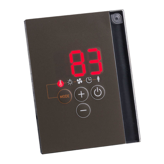
Seite 116: Bedienteil Pro D3
Gebrauchsanweisung für den Anwender S. 46/70 9.3. Bedienteil Pro D3 9.4. Bedienteil Pro D3i Anzeige Temperatur Lüfter Feuchte (nur Pro D3 / Pro D3i) Vorwahlzeit Zusatzausgang (nur Pro D2i / Pro D3i) Benutzerprogramme Licht Ein/Aus-Taste Minus-Taste Plus-Taste Mode-Taste... -
Seite 117: Zusatzausgang Bedienteil Pro D (Optional)
Gebrauchsanweisung für den Anwender S. 47/70 9.5. Zusatzausgang Bedienteil Pro D (optional) Ein/Aus-Taste Anzeige Standby für Fernwirken Plus-Taste Intensitätsanzeige Minus-Taste 9.6. Leistungsteil F Ein/Aus-Schalter E Lichtschalter... -
Seite 118: Bedienung
Gebrauchsanweisung für den Anwender S. 48/70 10. Bedienung 10.1. Licht am Leistungsteil einschalten (Reinigungsbeleuchtung) Das Licht in der Saunakabine kann am Leistungsteil unabhängig vom Ein/Aus- Schalter F eingeschaltet und ausgeschaltet werden. ● Um das Licht am Leistungsteil einzuschalten bzw. auszuschalten, drücken Sie den Lichtschalter E. -
Seite 119: Bedienteil Aktivieren
Wenn die Steuerung wie in 10.3. Bedienteil aktivieren beschrieben aktiviert wurde, kann bei den Modellen Pro D2i und Pro D3i, die Funktion 7 (Zusatz- ausgang) auch mit „Zusatzausgang Bedienteil Pro D“ aktiviert werden. ● Drücken Sie für eine Sekunde die Ein/Aus-Taste A des Zusatzausgang Be- dienteils. -
Seite 120: Sauna-Betrieb Starten
Gebrauchsanweisung für den Anwender S. 50/70 10.5. Sauna-Betrieb starten 1. Wählen Sie durch drücken der Mode-Taste D das Temperatur-Symbol 5 aus. Drücken Sie anschließend kurz die Ein/Aus-Taste A. ► Der Saunaofen wird eingeschaltet. 2. Stellen Sie mit der Plus-Taste B und Minus-Taste C die gewünschte Tem- peratur ein. -
Seite 121: Kombi-Betrieb Starten (Nur Pro D3 / Pro D3I)
Gebrauchsanweisung für den Anwender S. 51/70 10.7. Kombi-Betrieb starten (nur Pro D3 / Pro D3i) 1. Wählen Sie durch drücken der Mode-Taste D das Temperatur-Symbol 5 aus. Drücken Sie anschließend kurz die Ein/Aus-Taste A. ► Der Saunaofen wird eingeschaltet. 2. Stellen Sie mit der Plus-Taste B und Minus-Taste C die gewünschte Tem- peratur ein. -
Seite 122: Zusatzausgang Starten (Nur Pro D2I / Pro D3I)
Gebrauchsanweisung für den Anwender S. 52/70 Der Verdampfer (Feuchtefunktion 6) lässt sich nur starten, wenn der Saunaofen (Temperaturfunktion 5) eingeschaltet ist. Dabei ist die ma- ximal einstellbare Soll-Feuchte von der Saunatemperatur abhängig. Je höher die Saunatemperatur, desto niedriger ist der maximal einstellbare Feuchtewert. - Seite 123 Gebrauchsanweisung für den Anwender S. 53/70 Intensitätsregelung bei aktivierter Dimmfunktion Wenn die Dimmfunktion des Zusatzausgangs aktiviert ist, können Sie die Leistung des Zusatzgeräts auf einer Skala von 1 bis 7 einstellen. Der Wert 7 entspricht der vollen Leistung. 1. Wählen Sie durch drücken der Mode-Taste D das Zusatzausgang-Symbol 7 aus.
-
Seite 124: Intensität
Gebrauchsanweisung für den Anwender S. 54/70 Verwenden des optionalen Bedienteils „Zusatzausgang Bedienteil Pro D“ Das optionale Bedienteil ermöglicht das Ein- und Ausschalten des Zusatzaugangs sowie das Dimmen oder die Änderung der Temperatur. Der Zusatzaugsgang kann nur aktiviert werden, wenn die Steuerung bereits eingeschalten ist. -
Seite 125: Licht Einschalten
Gebrauchsanweisung für den Anwender S. 55/70 10.11. Licht einschalten Bei aktivierter Dimmfunktion Wenn die Dimmfunktion des Lichts aktiviert ist, können Sie die Leistung des Lichts von Stufe 0 bis Stufe 100 einstellen. Beim Wert 0 ist das Licht ausgeschaltet. Der Wert 100 entspricht der vollen Leistung. 1. -
Seite 126: Lüfter Starten
Gebrauchsanweisung für den Anwender S. 56/70 10.13. Lüfter starten Bei aktivierter Dimmfunktion Wenn die Dimmfunktion des Lüfters aktiviert ist, können Sie die Leistung des Lüfters auf einer Skala von 0 bis 100 einstellen. Der Wert 100 entspricht der vollen Leistung. 1. -
Seite 127: Vorwahlzeit Einstellen
Gebrauchsanweisung für den Anwender S. 57/70 10.15. Vorwahlzeit einstellen Sie können die Vorwahlzeit minutengenau einstellen. Die maximale Vorwahlzeit beträgt 6 Stunden. WARNUNG! Brandgefahr Brennbare Gegenstände, die auf dem heißen Saunaofen liegen, entzün- den sich und verursachen Brände. ● Legen Sie NIEMALS brennbare Gegenstände auf den Saunaofen. ●... -
Seite 128: Vorwahlzeit-Funktion Abbrechen
Gebrauchsanweisung für den Anwender S. 58/70 10.16. Vorwahlzeit-Funktion abbrechen ● Drücken Sie die Ein/Aus-Taste A, um die Vorwahlzeit-Funktion abzubrechen. ► Das Ablaufen der Vorwahlzeit wird abgebrochen. ► Die Steuerung startet sofort mit den zuvor eingestellten Funktionen. 10.17. Laufzeit einstellen Sie können bereits beim Starten der Sauna bestimmen, wie lange die Sauna in Betrieb sein soll. -
Seite 129: Standby Für Fernwirken Aktivieren
Gebrauchsanweisung für den Anwender S. 59/70 10.18. Standby für Fernwirken aktivieren Laut EN 60335-2-53 müssen Saunasteuerungen mit Fernstartfunktion manuell auf die Betriebsart „Standby für Fernwirken“ gestellt werden. Diese Aktivierung muss nach jedem Fernstart- und Fernstopp-Vorgang neu erfolgen. Führen Sie dazu folgende Schritte durch: 1. -
Seite 130: Nachtrockenprogramm Abrechen (Nur Pro D3 / Prod3I)
Gebrauchsanweisung für den Anwender S. 60/70 10.20. Nachtrockenprogramm abrechen (nur Pro D3 / ProD3i) Nach dem Kombi-Betrieb wird automatisch das Nachtrockenprogramm gestartet. Dabei wird die Saunakabine bei eingeschaltetem Lüfter für 30 Minuten auf 80 °C aufgeheizt. In der Anzeige 1 wird der Text "dry" angezeigt und das Temperatur- Symbol blinkt. -
Seite 131: Benutzerprogramme
Gebrauchsanweisung für den Anwender S. 61/70 11. Benutzerprogramme Mit Hilfe der Benutzerprogramme können bevorzugte Sauna-Einstellungen gespeichert und wieder abgerufen werden. Es stehen 5 voreingestellte Be- nutzerprogramme zur Verfügung, die nach den Vorstellungen der Anwender abgeändert werden können. Die Einstellungen folgender Funktionen werden in den Benutzerprogrammen abgespeichert: ●... -
Seite 132: Benutzerprogramme Aufrufen
Gebrauchsanweisung für den Anwender S. 62/70 11.2. Benutzerprogramme aufrufen 1. Wählen Sie durch drücken der Mode-Taste D das Benutzerprogramme- Symbol 4 aus. ► Das Benutzerprogramme-Symbol leuchtet. 2. Wählen Sie mit der Plus-Taste B und Minus-Taste C das gewünschte Be- nutzerprogramm (1 - 5) aus. 3. - Seite 133 Gebrauchsanweisung für den Anwender S. 63/70 Führen Sie folgende Schritte durch, um die Einstellungen in der Tabelle oben im Benutzerprogramm 2 zu speichern: 1. Wählen Sie durch drücken der Mode-Taste D das Temperatur-Symbol 5 aus. Drücken Sie anschließend kurz die Taste Ein/Aus-Taste A. ►...
-
Seite 134: Die Eco-Funktion
Gebrauchsanweisung für den Anwender S. 64/70 12. Die Eco-Funktion Die Eco-Funktion ermöglicht Ihnen, in den Pausen zwischen den Saunagängen Energie zu sparen. Die angeschlossenen Geräte laufen bei aktivierter Eco-Funktion mit reduzierter Leistung. Sie können zwischen einer 20-, 40-, oder 60-minütigen Saunapause wählen. -
Seite 135: Reinigung Und Wartung
Gebrauchsanweisung für den Anwender S. 65/70 13. Reinigung und Wartung 13.1. Reinigung ACHTUNG! Schäden am Gerät Die Saunasteuerung ist spritzwassergeschützt, trotzdem kann direkter Kontakt mit Wasser das Gerät beschädigen. ● Tauchen Sie das Gerät NIEMALS in Wasser. ● Übergießen Sie das Gerät nicht mit Wasser. ●... -
Seite 136: Problemlösung
Montageanweisung – nur für Fachpersonal S. 66/70 15. Problemlösung 15.1. Fehlermeldungen Die Saunasteuerung ist mit einer Diagnosesoftware ausgestattet, die beim Einschalten und im Betrieb die Systemzustände überprüft. Sobald die Diagno- sesoftware einen Fehler erkennt, schaltet die Saunasteuerung den Saunaofen ab. Fehler werden durch einen wiederkehrenden Warnton und das Blinken der Sym- bole 2 bis 8 angezeigt. -
Seite 137: Wassermangelanzeige (Nur Pro D3 / Pro D3I)
Gebrauchsanweisung für den Anwender S. 67/70 15.2. Wassermangelanzeige (nur Pro D3 / Pro D3i) Die Saunasteuerung verfügt im Kombi-Betrieb über eine automatische Wasser- mangel-Abschaltung, sofern Ihr Kombi-Ofen dies unterstützt. Ist der Wassertank des Verdampfers leer, wird dies durch einen wiederkehrenden Warnton und dem Text "FIL"... -
Seite 138: Technische Daten
Montage- und Gebrauchsanweisung S. 68/70 16. Technische Daten 16.1. Leistungsteil Umgebungsbedingungen Lagertemperatur: -25 °C bis +70 °C Umgebungstemperatur: -10 °C bis +40 °C Luftfeuchtigkeit: max. 95% Saunasteuerung Abmessungen (B x H x T): 307 x 175 x 57 mm Schaltspannung / dreiphasig 3N: 400 V AC Frequenz: 50 Hz... - Seite 139 Montage- und Gebrauchsanweisung S. 69/70 Einstellbereiche Temperatur: 30 °C bis 110 °C Feuchte: 0 % bis 100 % Dabei ist die maximal einstellbare Feuchte von der Saunatemperatur abhängig. Je höher die Saunatemperatur, desto niedriger ist der maximal einstellbare Feuchtewert. Thermische Sicherheit Ofenfühler mit Übertemperatur-Sicherung (139 °C Abschalttemperatur) Automatische Heizzeitbegrenzung einstellbar (6 h, 12 h, 18 h, 24 h)* Wahlweise Ein-Fühlerbetrieb oder Zwei-Fühlerbetrieb...
-
Seite 140: Bedienteil Pro D2 / Pro D2I / Pro D3 / Pro D3I
Abmessungen (B x H x T): 80 x 104 x 38 mm Montageausschnitt (B x H): 65 x 70 mm Schutzart (spritzwassergeschützt): IPX4 16.3. Zusatzausgang Bedienteil Pro D (optional) Umgebungsbedingungen Lagertemperatur: -25 °C bis +70 °C Umgebungstemperatur: 0 °C bis +100 °C Luftfeuchtigkeit: max. - Seite 141 NOTIZEN / APPUNTI / NOTES / NOTE / NOTITIES ………………………………………………….....………………………………………………………………... ……………………………………………………………..……………………………………………………………... …………………………………………………………….....………………………………………………………... …………………………………………………….....………………………………………………………………... ……………………………………………………………..……………………………………………………………... ……………………………………………………………..……………………………………………………………... ……………………………………………………………..…………………………………………………………... …………………………………………………………….....………………………………………………………... …………………………………………………………….....………………………………………………………... …………………………………………………………….....………………………………………………………... …………………………………………………………….....………………………………………………………... …………………………………………………………….....………………………………………………………..…………………………………………………………….....………………………………………………………... …………………………………………………………….....………………………………………………………... …………………………………………………………….....………………………………………………………... …………………………………………………………….....………………………………………………………... …………………………………………………………….....………………………………………………………... …………………………………………………………….....………………………………………………………... …………………………………………………………….....………………………………………………………...
- Seite 142 GmbH | Division of Harvia Group | Wartenburger Straße 31, A-4840 Vöcklabruck T +43 (0) 7672/22 900-50 | F -80 | info@sentiotec.com | www.sentiotec.com...