Seite 1
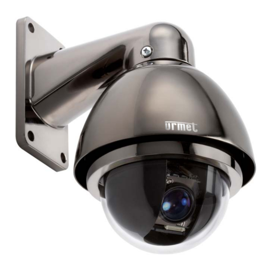
THERA 5 MINIDOME P/T/Z ANTIVANDALO DA ESTERNO CON ZOOM 10X THERA 5 P/T/Z VANDAL-PROOF OUTDOOR MINIDOME WITH 10X ZOOM THERA 5 P/T/Z VANDALENSICHER AUSSEN MINIDOME KAMERA MIT 10X ZOOM Sch./Ref./Typ 1092/602 MANUALE DI INSTALLAZIONE ED USO INSTALLATION AND USER MANUAL BEDIENUNGSANLEITUNG...
ITALIANO INDICE Informazioni generali ..........................3 Descrizione del prodotto......................3 Apertura della confezione....................... 3 1.2.1 Contenuto della confezione ........................3 Organizzazione del documento....................3 Importanti norme di sicurezza ......................4 Procedure di installazione........................6 Configurazione di un sistema minimale per l’uso di THERA 5..........6 Tipologie di installazione ......................
DESCRIZIONE DEL PRODOTTO La minidome Sch.1092/602 offre elevate prestazioni in termini di qualità video e di manovrabilità, con la possibilità di riprendere immagini a colori ad alta qualità durante il giorno ed in bianco e nero durante la notte.
Sono qui riportate importanti norme da seguirsi scrupolosamente per operare la telecamere Sch.1092/602 e relativi accessori in condizioni di completa sicurezza. Nel seguito con il termine “sistema video” si intende una minidome Sch.1092/602 comprendente tutto quanto possa servire per renderla operativa (ad esempio, alimentazione, cavi, supporti, tastiera di controllo, od altro ancora).
Seite 5
TV o simili, le immagini potrebbero presentare delle interferenze. In tal caso spostare i cavi o reinstallare l'apparecchio. Privacy e Copyright La minidome 1092/602 è un dispositivo per sistemi TVCC. La registrazione delle immagini è subordinata alle leggi vigenti nel paese di utilizzo. È inoltre vietata la registrazione di immagini protette da Copyright.
PROCEDURE DI INSTALLAZIONE Questa sezione fornisce istruzioni dettagliate per l’installazione delle minidome THERA 5 Urmet Domus. Le istruzioni presuppongono da parte dell’installatore una buona conoscenza delle tecniche di installazione e l’adozione di metodi d’installazione sicuri. CONFIGURAZIONE DI UN SISTEMA MINIMALE PER L’USO DI THERA 5 La minidome THERA 5 contiene un ricevitore incorporato che decodifica i comandi provenienti dalla tastiera di comando Sch.1092/620 (fare riferimento al capitolo 4.2);...
3.2.1 INSTALLAZIONE A PARETE. • Prima d’iniziare l’installazione, assicurarsi che tutte le unità da collegare non siano alimentate. • Posizionare sulla staffa da parete l’anello di tenuta in gomma (oring), a corredo, nella apposita sede. • Inserire il cavo di collegamento della dome, in dotazione, all’interno della staffa fino a farlo fuoriuscire dalla parte opposta.
Seite 8
• Bloccare la staffa alla dome utilizzando le viti con la rondella in gomma, a testa bombata a corredo avvitandole saldamente nei fori presenti ai lati della staffa. • Posizionare la dome nel punto prescelto della parete avendo cura di far passare il cavo attraverso l’asola situata nella staffa o praticare un ulteriore foro sulla parete in corrispondenza del cavo in uscita dalla staffa di diametro sufficiente al passaggio del cavo intestato).
Seite 9
INSTALLAZIONE A PARETE CON POWER BOX SCH.1092/628 (Non a corredo) • Prima d’iniziare l’installazione, assicurarsi che tutte le unità da collegare non siano alimentate. • Eseguire i fori sulla superficie di appoggio prevista e fissare il Power Box utilizzando i 4 fori presenti alle estremità...
• Eseguire il collegamento dell’alimentazione a 230 Vca inserendo il cavo di sezione e lunghezza adeguata allo scopo (vedi Requisiti per i cavi di collegamento) nel foro più piccolo corredato di pressa cavo presente nel lato inferiore del Box e collegandolo ai morsetti presenti sulla scheda dopo aver rimosso il coperchio di protezione.
Seite 11
• Posizionare l’anello di raccordo, in dotazione, nella sede superiore della dome avendo cura di allineare i due fori presenti sulla dome ai due fori presenti sull’anello aiutandosi con i riferimenti presenti su entrambe le parti. • Collegare la morsettiera del cavo alla morsettiera della dome come indicato in figura. •...
COLLEGAMENTI • Collegare il cavo in dotazione alla dome per mezzo delle morsettiere. • Collegare la seconda estremità del cavo al dispositivo video per mezzo del connettore BNC maschio. • Collegare i due fili della RS485 per mezzo di morsettiera o eseguendo una saldatura alla borchia della tastiera (Sch.1092/620) rispettando le polarità...
3.2.2 REQUISITI DEI CAVI PER IL COLLEGAMENTO Sono richiesti tre tipi di cavo: 1. Il cavo video, che trasporta il segnale video composito standard alla postazione di osservazione remota. Normalmente si utilizza un cavo coassiale da 75 Ohm. 2. Il cavo di alimentazione per la minidome THERA 5 (alimentatore da 24Vca). Per determinare le dimensioni del cavo, vedere la sezione “Dimensioni dei cavi d’alimentazione”...
MODALITÀ DI FUNZIONAMENTO FUNZIONAMENTO ALL’ACCENSIONE Alla prima accensione, la dome utilizza le impostazioni di default di fabbrica. Le impostazioni, se variate, vengono memorizzate in maniera permanente e sono disponibili anche alle successive accensioni della dome. Da notare che in qualsiasi momento si possono riportare le impostazioni al loro valore di default di fabbrica agendo sulla voce di menu opportuna.
4.2.1 SINTASSI DEI COMANDI ESEGUIBILI DA TASTIERA SCH.1092/620 È possibile dare comandi da tastiera usando tasti singoli, oppure una combinazione di tasti. La sintassi di descrizione del comando formato da tasti è la seguente. Sintassi di comandi formati da tasti La sintassi usata in questo manuale per i comandi formati da tasti consiste in una serie di elementi che possono essere parole oppure numeri a tre cifre decimali.
SELEZIONE DELLA DOME Prima di poter eseguire qualunque comando, si rende necessario selezionare la dome su cui si vuole agire. Ad esempio, per selezionare la dome numero 1 si usa il seguente comando: CAM + 1 + ENTER A completamento dell’operazione il display della tastiera indica : A001. OPERAZIONI DI MANOVRA DELLA DOME Una volta selezionata, la dome può...
La funzione di AUTO FLIP consente di seguire un soggetto che arrivando da una direzione passa sotto la dome e prosegue in linea retta. Per fare questo, basta mantenere premuto il tasto DOWN seguendo il movimento dell’oggetto. 4.4.2 FUNZIONI DI MODIFICA INGRANDIMENTO (ZOOM) L’ingrandimento della dome può...
4.4.5 IMPOSTAZIONE E RICHIAMO DI POSIZIONI PREIMPOSTATE (PRESET) La minidome THERA 5 memorizza fino a 128 configurazioni di pan, tilt e zoom (dette posizioni preimpostate oppure preset) in modo tale da permettere il richiamo di una di queste posizioni in un qualsiasi momento. Nota Bene Nella memorizzazione dei preset occorre tenere in considerazione che alcuni sono riservati e che non possono essere ne memorizzati ne utilizzati per posizionare la dome.
Opzione Valore Spiegazione I menu sono solo in lingua inglese. Language ENGLISH Menu relativo alle informazioni sul prodotto (vedi par. 4.5.1 ). Dome Information Menu relativo alle visualizzazioni (vedi par. 4.5.2 ). Display Informations Menu relativo alle programmazioni principali (vedi par. 4.5.3 ). Control Options Menu relativo alle programmazioni secondarie (vedi par.
4.5.3 Impostazioni da menu relative alle programmazioni principali (Control Options) Dal menu di primo livello, scegliendo <CONTROL OPTIONS> e relativi sotto menu si ottiene l’accesso ai principali menu per la programmazione di THERA 5 CONTROL OPTIONS >1 Auto Flip ON 2 Proportional Speed ON 3 Pan Reverse OFF 4 Tilt Reverse OFF...
4.5.4 IMPOSTAZIONI DA MENU RELATIVE ALLE PROGRAMMAZIONI PRINCIPALI (DIAGNOSTIC OPTIONS) Dal menu di primo livello, scegliendo <DIAGNOSTIC OPTIONS> e relativi sotto menu si ottiene l’accesso ai principali menu per la gestione e la diagnostica di THERA 5 Diagnostic Options >1 Clear Memory 2 Restore Def Setting 3 Color System 4 Dome Reset...
Opzione Valore Spiegazione Questa opzione permette di nominare la dome ON ÷ OFF CAM TITLE utilizzando fino massimo caratteri. (Vedi oltre) Questa opzione consente di selezionare la MANUAL ÷ AWC-SET WHITE BAL modalità di bilanciamento del bianco. (Vedi ÷ ATW oltre) Questa opzione consente di selezionare il ÷...
Seite 23
Questa funzione consente di selezionare la modalità del bilanciamento del bianco. Selezionando questa voce di menu è possibile scegliere fra le opzioni MANUAL, AWC-SET e ATW. Opzione Valore Spiegazione Questa opzione consente regolare MANUAL RED ÷ BLUE manualmente il bilanciamento del bianco. Auto White Balance: regolazione automatica per interni da utilizzare in ambienti con AWC-SET...
4.5.7.3 Backlight – BLC – compensazione controluce Un oggetto inquadrato con forte luce proveniente da dietro solitamente appare scuro e poco visibile rispetto al resto dell’immagine. La funzione BLC permette di ovviare a questo inconveniente ed ottenere una buona compensazione. Selezionando questa voce di menu è...
MODE Selezionando MODE è possibile scegliere fra le opzioni MANUAL (manuale), AUTO (automatica) e ONE- PUSH (una pressione). Selezionando MANUAL e premendo OPEN si accede al seguente sottomenu: ZOOM/FOCUS POS SETUP :TELE :WIDE :NEAR :FAR Press SET to Return Utilizzando I tasti “FOCUS” e “ZOOM” è possibile eseguire le regolazioni desiderate. TELE (avvicina l’immagine);...
D-ZOOM Selezionando D-ZOOM è possibile scegliere fra le opzioni ON (attivo) e OFF (disattivo). Selezionando ON e premendo OPEN si accede al seguente sottomenu: D-ZOOM LIMIT SETUP LIMIT Press SET to Return Selezionando LIMIT è possibile variare la percentuale di ingrandimento potendo scegliere fra i valori compresi tra X2 fino a X10.
Seite 27
IRIS - IRIDE Selezionando IRIS è possibile scegliere fra le opzioni MANUAL (manuale) e AUTO (automatico). Selezionando MANUAL e premendo OPEN si accede al seguente sottomenu: IRIS MANUAL SETUP IRIS VAL 85 ■■■■■■■█■■■ Selezionando IRIS VAL e premendo i tasti “freccia” è possibile variare la percentuale di apertura dell’iride della dome scegliere fra i valori compresi tra 1 a 100.
SENS-UP (DSS) – VARIAZIONE DELLA SENSIBILITA’ DELLA DOME IN FUNZIONE DELLA VARIAZIONE DI LUCE Questo dispositivo consente di effettuare riprese di scene in condizioni di scarsa luminosità. Alla graduale diminuzione della luminosità, corrisponde una diminuzione dei frame per secondo (numero di immagini/secondo) aumentando la sensibilità...
Seite 29
DAY/NIGHT - VARIAZIONE DEL FUNZIONAMENTO DELLA DOME IN FUNZIONE DELLA VARIAZIONE DI LUCE PRESENTE SULLA SCENA La dome, che normalmente riprende le immagini a colori, in condizioni di scarsa illuminazione, commuta automaticamente il suo funzionamento da “colore” a “bianco/nero”, in questo modo viene ottimizzata la qualità...
Selezionando LEVEL e premendo i tasti “freccia” è possibile variare la definizione delle immagini potendo scegliere fra valori che variano fra 0 fino a 31. Selezionare END e premere CLOSE per tornare al menu precedente. 4.5.8 IMPOSTAZIONI DA MENU RELATIVE ALLE PROGRAMMAZIONI (FUNCTION PROGRAMMING) Dal menu di primo livello, scegliendo <FUNCTION PROGRAMMING>...
4.5.8.1 Preset - memorizzazione della posizione e dello zoom della dome Selezionando PRESET e premendo OPEN si accede al seguente sottomenu: Preset >1 Number 2 Set Preset 3 Call Preset 4 Delete Preset 5 Name ------------- 6 AlaName Display OFF IRIS CLOSE to Exit Opzione Valore...
Seite 32
Opzione Valore Spiegazione Questa opzione consente di identificare i VectorScan Number 1 ÷ 6 che si vogliono memorizzare. E’ possibile selezionare un massimo di 6 VectorScan Questa opzione consente di definire le operazioni che devono essere eseguite dal VectrorScan selezionato Program a VectorScan (max 16).
Dwell – è il tempo di sosta prima che venga attivata la successiva azione; è possibile scegliere fra valori di 1 a 9; premere il tasto OPEN per selezionare il tempo di sosta desiderato. Nota Bene Affinché il numero di azione sia attiva è necessario inserire tutti i parametri richiesti e precedentemente elencati.
NAME Selezionando NAME e premendo OPEN si accede al seguente sottomenu nel quale è possibile nominare il preset : - - - - - - - - - - - - - - - - 0123456789ABCDEFRGHIJKLMN OPQRSTUVWXYZ- IRIS CLOSE When Done Utilizzare i tasti freccia per spostarsi nella posizione nella quale si vuole inserire il carattere.
Seite 35
Questa opzione consente di memorizzare le coordinate finali del settore relative al PAN. Premendo OPEN e posizionandosi per mezzo dei tasti freccia sulla inquadratura fine settore da Pan End POS 0,0 ÷ 359,9 ÷ 0,0 ÷ 90,0 memorizzare, è possibile vedere a monitor anche le coordinate relative alla inquadratura visualizzata.
4.5.8.5 Masking zone- zona di mascheramento Permette di escludere all’operatore la visione di parti delle immagini riprese e visualizzate a monitor. Selezionando MASKING ZONE e premendo OPEN si accede al seguente sottomenu: Masking Zone >1 Number 2 Mask Edit 3 Mask Display IRIS CLOSE to Exit Opzione Valore...
Seite 37
PARK ACTION La PARK ACTION è l’azione che viene eseguita automaticamente dopo un periodo (PARK TIME) di inattività della Dome. Selezionando PARK ACTION e premendo IL TASTO FRECCIA DESTRA si accede al seguente sottomenu: Park Action >1Action _________ 2 Number _________ 3 Park Time _________...
Seite 38
Opzione Valore Spiegazione Questa opzione consente di selezionare una delle azioni descritte nella tabella precedente. None ÷ Preset ÷ NOTA: se l’opzione selezionata sarà None, nel momento Action VectorScan ÷ Pattern dell’accensione verrà eseguita l’ultima funzione svolta ÷ PanScan ÷ AutoScan dalla dome prima dello spegnimento, o il Park Time nel caso in cui prima dello spegnimento non fossero state richieste alla dome funzioni programmate).
4.5.8.7 Alarm in programming – azioni collegate agli allarmi QUESTA FUZIONE E’ DISPONIBILE SOLO SE SONO PRESENTI IL POWER BOX 1092/628 E/O LE SCHEDE ALLARME SUPPLEMENTARI 1092/685 Selezionando ALARM IN PROGRAMMING e premendo OPEN si accede al seguente sottomenu: Alarm In Programming >1Channel Number 2 Label Edit ____...
Seite 40
Opzione Valore Spiegazione Preset÷VectorScan÷ Questa opzione consente di selezionare una delle azioni Action Patter÷PanScan÷ descritte nella tabella delle PARK ACTION. AutoScan Questa opzione consente di definire specificatamente quale singola azione si vuole attivare. Il numero selezionabile della singola azione varia in funzione della azione precedentemente selezionata (da 1 a 165 Number 1 ÷...
IMPOSTAZIONI HARDWARE (DIP-SWITCH) 4.6.1 IMPOSTAZIONE DELLA DOME Per eseguire le impostazioni di indirizzo,di baud rate e protocollo di comunicazione è necessario rimuovere la cupola estera e la cupola interna della dome procedendo nel seguente modo: Ruotare in senso antiorario la cupola esterna per circa ¼ di giro per sbloccarla dalla sede. Ruotare in senso antiorario la cupola interna per circa ¼...
Seite 42
Assegnazione dell’indirizzo della dome con protocollo pelco D A ciascuna dome si può assegnare uno fra 255 indirizzi possibili agendo sugli 8 interruttori del dip-switch della Serie 2. L’indirizzo assegnato può essere determinato dalla tabella seguente. DIP-SWITCH SERIE 2 INDIRIZZO 0 (NON USARE) DS1092-090...
BAUD RATE PROTOCOLLO PELCO D PELCO P NOTA BENE Si consiglia la selezione del protocollo PELCO D alla baud-rate di 9600 bps per garantire il corretto funzionamento dei prodotti della famiglia THERA con i prodotti compatibili del catalogo Urmet Domus DS1092-090...
COMANDI SPECIALI I comandi speciali, eseguibili da tastiera sotto descritti, possono essere realizzati inviando il comando CALL o PRESET seguito dai numeri che ne identificano l’azione. COMANDO DA TASTIERA FUNZIONE CALL 51 Memorizza la velocità del Panscan PRESET 51 Avvia il Preset Tour di default CALL 52 Abilita il PanScan PRESET 52...
CARATTERISTICHE TECNICHE Sono qui riassunte le principali caratteristiche tecniche della telecamere Sch.1092/602. Caratteristiche generali Valore Peso 1000 g. Dimensioni ∅ x H 122 x193 mm Tensione d’alimentazione 24VAC Consumo massimo Grado di protezione IP66 -25 ÷ +60°C Temperatura di utilizzo...
Seite 46
Caratteristiche meccaniche Valore Velocità manuale di spostamento orizzontale 0.1 ÷ 240°/s Velocità manuale di spostamento verticale 0.1 ÷ 120°/s Velocità in preset 300°/s Controllo remoto Valore Interfaccia RS485 Protocollo Pelco-D Data rate 2400bps, 4800bps, 9600bps (selezionabili tramite dip-switch) NOTA BENE •...
Seite 47
ENGLISH INDEX GENERAL INFORMATION ..............Fehler! Textmarke nicht definiert. Product Description ............Fehler! Textmarke nicht definiert. Package Opening ............Fehler! Textmarke nicht definiert. 1.2.1 Package Contents ................Fehler! Textmarke nicht definiert. Structure of this manual ..........Fehler! Textmarke nicht definiert. IMPORTANT SAFETY NOTES .............Fehler! Textmarke nicht definiert. INSTALLATION PROCEDURES............Fehler! Textmarke nicht definiert.
Dear Customer, Thank your for purchasing this product. This document shows how to install and use the URMET Domus THERA 5 Ref.1092/602. Read this manual which contains information for correct, safe use carefully. Keep this manual at hand so that you can refer to it when needed.
IMPORTANT SAFETY NOTES The following important notes must be followed carefully to work the Thera 5 Ref.1092/602 camera and respective accessories in total safety. The term “video system” here means a camera and all components needed for its operation (e.g., power, leads, supports, control board and more).
Seite 50
Privacy and Copyright The 1092/602 camera a CCTV system devices. Recording of imagines is subject to the laws in force in your country. Recording of images protected by copyright is forbidden. Product users shall be responsible for checking and respecting all local rules and regulations concerning monitoring and recording video signals.
INSTALLATION PROCEDURES This section contain detailed instructions for installing Urmet Domus 1092/602 camera. These instructions assume that the installer has a good knowledge of installation techniques and is capable of adopting safe installation methods. BASIC SYSTEM CONFIGURATION FOR THE USE OF THERA 5 The minidome THERA 5 has an embedded receiver which decodes the commands coming from the control keypad Ref.
9.2.1 WALL MOUNTING • Before starting installation, check that all devices to be connected are not powered. • Place on the wall mounting bracket the provided o-ring, in the suitable seat. • Fit the dome connection cable, provided, into the bracket, until it comes out on the opposite side. •...
Seite 53
• Fix the bracket to the dome using the provided round head screws with the rubber washer, by screwing them tightly in the holes on the bracket sides. • Fix the dome to the wall, taking care that the cable goes through the slot in the bracket, or make another hole on the wall, in order to allow the passage of the cable.
Seite 54
WALL MOUNTING WITH POWER BOX REF. 1092/628 (not provided) • Before starting installation, check that all devices to be connected are not powered. • Make the holes on the support base and fix the Power Box using the 4 holes on the device ends. •...
• Connect 230Vac power supply by putting the cable of suitable length and type (see Requirements for connection cables) in the smallest hole provided with grommet, present on the lower side of the Power Box and connect it to the terminal pins on the card, after removing the protection lid. •...
Seite 56
• Put the provided junction ring in the upper seat of the dome, taking care that the two holes on the dome match the two holes on the ring, using the references on both the sides. • Connect the cable terminal block to the dome terminal block, as shown in the figure. •...
CONNECTIONS • Connect the provided cable to the dome using terminal blocks. • Connect the second end of the cable to the video device, using the BNC male connector. • Connect the two wires of RS485 with a terminal block or welding them to the keypad (Ref. 1092/620) wiring junction box, observing polarity: ORANGE + (positive) - YELLOW –...
Seite 58
9.2.2 REQUIREMENTS FOR CONNECTION CABLES Three types of cables are required: 1. The video cable, used to bring a standard composite video signal to the remote surveillance station. Usually a 75 Ohm coax cable is used. 2. The power supply cable for the minidome THERA 5 (24Vac power supply unit). To define cable dimensions, see “Power supply cables dimensions”...
10 OPERATING MODE 10.1 OPERATION AT POWER-UP At the first power-up, the dome operates with the factory default configurations. If settings are changed, they are permanently stored and will be available also for future dome power-up. Notice that at any time settings can be restored to default values using the suitable menu item.
Seite 60
10.2.1 KEYPAD REF. 1092/620 COMMAND SYNTAX Commands can be sent by the keypad using single buttons or several buttons. The command syntax is the following. Multiple buttons command syntax The command syntax described in this manual consists in elements which can be words or 3-decimal digits numbers.
Seite 61
10.3 DOME SELECTION Before activating any command, the dome must be selected. For example, use the following command to select the dome number 1: CAM + 1 + ENTER After this operation, the keypad display shows: A001. 10.4 DOME MOVEMENT OPERATIONS Once the camera has been selected, the operator can directly perform on the keypad the following operations (described below): −...
Seite 62
The AUTO FLIP function allows to follow an object which moves under the dome and goes straight. To do this, keep the DOWN button pressed following the movement of the object. 10.4.2 ZOOM FUNCTIONS The dome zoom can be changed using the commands TELE and WIDE. Use TELE command to zoom in the image and WIDE command to zoom out the image.
Seite 63
10.4.5 SETTING AND RECALL OF PRESETS The minidome THERA 5 stores up to 128 pan, tilt and zoom configurations (called presets), therefore these positions can be recalled at any moment. Note When storing presets, consider that some positions are reserved and can neither be stored nor used to set the dome position.
Option Value Description Menus are only in English. Language ENGLISH Product information menu (see par. 4.5.1 ). Dome Information Display menu (see par. 4.5.2 ). Display Informations Main programming menu (see par. 4.5.3 ). Control Options Secondary programming menu (see par. 4.5.4 ). Diagnostic Options Menu used to configure the text associated to the dome (see par.
10.5.3 Settings of main programming procedures via the menu (Control Options) From the first level menu, select <CONTROL OPTIONS> and its submenus to access the main menus for programming THERA 5. CONTROL OPTIONS >1 Auto Flip ON 2 Proportional Speed ON 3 Pan Reverse OFF 4 Tilt Reverse OFF 5 Vector Scan Still OFF...
10.5.4 SETTINGS OF MAIN PROGRAMMING VIA THE MENU (DIAGNOSTIC OPTIONS) From the first level menu, select <DIAGNOSTIC OPTIONS> and its submenus to access the main menus for THERA 5 management and diagnostics. Diagnostic Options >1 Clear Memory 2 Restore Def Setting 3 Color System 4 Dome Reset IRIS CLOSE to Exit...
Seite 67
Option Value Description This option allows to give a name to the ON ÷ OFF CAM TITLE dome, using up to 20 characters max. (see below). MANUAL ÷ AWC-SET This option allows select white WHITE BAL balancing mode (see below). ÷...
Seite 68
10.5.7.2 White bal – white balancing This function allows to select the white balancing mode. Select this menu item to choose MANUAL, AWC-SET and ATW options. Option Value Description This option allows to manually adjust the MANUAL RED ÷ BLUE white balancing.
Seite 69
10.5.7.4 Focus– zoom adjustment This function allows to access the submenu used to set dome adjustments. Select this item and press OPEN to access the following submenu: FOCUS SETUP MODE MANUAL ZOOM TRK ZOOM SPEED FAST D-ZOOM DISP ZOOM MAG ZOOM POS INIT LENS INIT Option...
MODE Select MODE to choose among MANUAL, AUTO (automatic) and ONE-PUSH options. Select MANUAL and press OPEN to access the following submenu: ZOOM/FOCUS POS SETUP :TELE :WIDE :NEAR :FAR Press SET to Return Use the buttons “FOCUS” and “ZOOM” to perform the desired adjustments. TELE (zoom in);...
Seite 71
D-ZOOM Select D-ZOOM to choose between ON (active) and OFF (not active) options. Select ON and press OPEN to access the following submenu: D-ZOOM LIMIT SETUP LIMIT Press SET to Return Select LIMIT to change the percentage of zoom, choosing among values from X2 to X10. Select END and press CLOSE to go back to the previous menu.
Seite 72
IRIS Select IRIS and choose between MANUAL and AUTO (automatic) options. Select MANUAL and press the button OPEN to access the following submenu: IRIS MANUAL SETUP IRIS VAL 85 ■■■■■■■█■■■ Select IRIS VAL and press the arrow buttons to change the iris opening and choose values from 1 to 100. This adjustment must be changed only when the dome is used in extreme conditions.
Seite 73
SENS-UP (DSS) – DOME SENSITIVITY ADJUSTMENT ACCORDING TO LIGHT CHANGE This device allows to shoot scenes in low-light conditions. When the brightness gradually decreases, also the frame per second is reduced (number of images/second), increasing the dome sensitivity. Select SENS-UP to choose between AUTO (automatic) and OFF (disabled). Select AUTO and press OPEN to access the following menu: SENS-UP LIMIT SETUP LIMIT...
Seite 74
DAY/NIGHT – DOME OPERATION CHANGE ACCORDING TO VARIATION OF LIGHT PRESENT IN THE SCENE The dome usually captures colour images, but under low-light conditions it automatically switches its operation mode from “colour” to “black/white”. In this way the quality of the captured image is optimized. Select DAY/NIGHT to choose among AUTO1 (automatic), AUTO2 (automatic), EXT, COLOR and B/W (black/white) options.
10.5.8 MENU SETTINGS CONCERNING PROGRAMMING (FUNCTION PROGRAMMING) In the first level menu, select <FUNCTION PROGRAMMING> and its submenus to gain access to the next menu levels for programming THERA 5. FUNCTION PROGRAMMING >1 Preset 2 Program VectorScan 3 Pattern 4 Sector Setup 5 Masking Zone 5 Motion 6 Alarm In Programming...
Seite 76
10.5.8.1 Preset – storage of dome position and zoom Select PRESET and press OPEN to access the following submenu: Preset >1 Number 2 Set Preset 3 Call Preset 4 Delete Preset 5 Name ------------- 6 AlaName Display OFF IRIS CLOSE to Exit Option Value Description...
Seite 77
10.5.8.2 Program vectorscan – definition of a path made by preset, pattern and vectorscan Select PROGRAM VECTORSCAN and press OPEN to access the following submenu: Opzione Valore Spiegazione This option allows to identify VectorScan to be stored. Number 1 ÷ 6 Up to 6 VectorScan max.
Seite 78
Dwell – is the dwell time before the next action is activated; values from 1 to 9 can be selected; press the button OPEN to select the desired dwell time. Note In order to ensure that the action number is active, enter all the required parameters listed before. 10.5.8.3 Pattern –...
Seite 79
NAME Select NAME and press OPEN to access the following sub menu, where to give a name to the preset: - - - - - - - - - - - - - - - - 0123456789ABCDEFRGHIJKLMN OPQRSTUVWXYZ- IRIS CLOSE When Done Use the arrow buttons to move the cursor on the position where the character must be entered.
Seite 80
This option allows to store the TILT start coordinates of the sector. Press OPEN and with the arrow buttons move the dome to the starting Tilt Start POS 0,0 ÷ 359,9 ÷ 0,0 ÷ 90,0 shot to be stored. The user can see on the display the coordinates of the displayed shot.
Seite 81
10.5.8.5 Masking zone It allows to hide from the operator certain parts of the images captured and displayed on the monitor. Select MASKING ZONE and press OPEN to access the following submenu: Masking Zone >1 Number 2 Mask Edit 3 Mask Display IRIS CLOSE to Exit Option Value...
Seite 82
PARK ACTION The PARK ACTION is the action which is automatically executed after an inactivity time (PARK TIME) of the Dome. Select PARK ACTION and press the right arrow button to access the following submenu: Park Action >1Action _________ 2 Number _________ 3 Park Time _________...
Seite 83
Option Value Description This option allows to select one of the actions described in the previous table. None ÷ Preset ÷ NOTE: If the selected option is None, the function Action VectorScan ÷ Pattern performed by the dome at power-up will be the one in ÷...
10.5.8.7 Alarm in programming – actions associated to alarms THIS FUNCTION IS AVAILABLE ONLY IN PRESENCE OF POWER BOX 1092/628 AND/OR ADDITIONAL ALARM CARDS 1092/685. Select ALARM IN PROGRAMMING and press OPEN to access the following submenu: Alarm In Programming >1Channel Number 2 Label Edit ____...
10.6 HARDWARE SETTINGS (DIP-SWITCH) 10.6.1 DOME SETTING To set address, baud rate and communication protocol, remove the external and internal cover of the dome as follows: Rotate the external cover about ¼ turn counterclockwise to unlock it. Rotate the internal cover about ¼ turn counterclockwise to unlock it. After the two covers have been removed, it is possible to gain access to the dip-switches inside the dome.
Seite 86
pelco D protocol Dome address assignment with One of the 255 available addresses can be assigned to each dome, setting the 8 switches of the dip-switch of Series 2. The assigned address is defined by the following table. DIP-SWITCH SERIES 2 ADDRESS 0 (DO NOT USE) DS1092-090...
4) on the electronic card of the dome, following the positions indicated below: BAUD RATE PROTOCOL PELCO D PELCO P NOTE It is suggested to select PELCO D protocol at 9600 bps baud-rate to ensure the correct operation of THERA products with compatible products of Urmet Domus catalogue. DS1092-090...
Seite 88
11 SPECIAL COMMANDS The below described special commands, sent by the keypad, can be executed sending the command CALL or PRESET, followed by the numbers which identify the respective action. KEYPAD COMMAND FUNCTION CALL 51 Stores Panscan speed PRESET 51 Starts the default Preset Tour CALL 52 Enables PanScan...
12 TECHNICAL SPECIFICATIONS The main technical characteristics of cameras Ref.1092/602 are the following: General characteristics Value Weight 1000 g. Dimensions ∅ x H 122 x193 mm Power supply voltage 24VAC Max. power consumption Protection grade IP66 -25 ÷ +60°C Working temperature range...
Seite 90
DEUTSCH INHALTSVERZECIHNIS Allgemeine Hinweise..........................91 Produktbeschreibung......................91 Öffnen der Verpackung ......................91 1.2.1 Verpackungsinhalt..........................91 Aufbau der Bedienungsanleitung ..................91 Wichtige Sicherheitshinweise......................92 Vertraulichkeit und Copyright ........................... 93 Installation............................. 94 Basis System Konfiguration zur Nutzung der Thera 5 ............94 Installationsmöglichkeiten ....................
ALLGEMEINE HINWEISE Lieber Kunde, wir danken Ihnen für den Kauf dieses Produkts. In dieser Bedienungsanleitung finden Sie Beschreibungen über die Aufstellung und den Gebrauch der PTZ Kamera 1093/602 Lesen Sie diese Unterlagen sorgfältig durch, damit Sie das Gerät richtig und sicher einsetzen können. Halten Sie die Bedienungsanleitung griffbereit, so dass Sie im Zweifelsfall immer nachschauen können.
Wichtige Sicherheitshinweise Die folgenden wichtigen Hinweise sollten beachtet werden, damit die Kamera Thera 5 Typ 1092/602 und entsprechend auch das Zubehör mit Sicherheit perfekt funktioniert. Der nachfolgend benutzte Ausdruck “Videosystem” benennt die Kamera und alle Komponenten (z. B. Einspeisung, Leitungen, Halter, Steuerpult und anderes.)die für die ordnungsgemäße Funktion der Kamera eingesetzt werden.
Reparaturen Keinesfalls sollte bei einem Defekt versucht werden die Kamera (oder irgendein anderer Teil des Videosystems) selbst zu reparieren. Es könnte beim Versuch der Reparatur zu Stromschlägen kommen. Nehmen Sie in jedem Fall Kontakt mit einer Fachfirma auf, um das Gerät reparieren zu lassen. Beschädigungen die eine professionelle Hilfe benötigen Trennen der Spannungsversorgung (Schutz- oder Trennschalter ausschalten) und den Servicetechniker in den unten Fällen anrufen:...
INSTALLATION Dieser Abschnitt behandelt die detaillierte Vorgehensweise bei der Installation der Minidome PTZ Kamera 1092/602. Diese Vorgehensweise setzen beim Installateur die Kenntnisse von Installationstechniken und die Anwendung von Sicherheitsmaßnahmen im Umgang mit elektrischen Betriebsmitteln voraus. BASIS SYSTEM KONFIGURATION ZUR NUTZUNG DER THERA 5 Die Minidome PTZ Kamera THERA 5 verfügt über einen integrierten Empfänger welcher die Befehle des...
3.2.1 WANDMONTAGE MIT STANDARDHALTER • Vor der Installation sicherstellen, dass alle anzuschließenden Einheiten von der Versorgung getrennt sind. • Positionierung des im Lieferumfang enthaltenen Dichtungsrings in der dafür vorgesehen Aussparung des Wandhalters. • • Das vorkonfektionierte Kabel in die zentrale Öffnung der Wandhalterung einführen, um es am Ende des Rohrs austreten zu lassen.
Seite 96
• Das Anschlussrohr am Dome-Gehäuse mit den im Lieferumfang enthaltenen Rundkopf-Schrauben inklusiv Dichtungsring befestigen. • Den Dome an der zuvor ausgewählten Stelle an der Wand montieren und dabei darauf achten, das Anschlusskabel über die Aussparung oder durch ein entsprechend größeres Loch in der Wand zu führen.
Wandmontage mit Power Box. Typ 1092/628 (nicht im Lieferumfang) Vor der Installation sicherstellen, dass alle anzuschließenden Einheiten von der Versorgung getrennt sind. Nach Ermittlung der Stelle, an der die Kamera zu installieren ist, wie folgt vorgehen: Die Bohrungen zur Befestigung je nach Wandtyp (Zement, Holz, etc.) und der verwendeten Vorrichtung zur Befestigung anbringen.
Seite 98
• Das Kabel (Anforderungen siehe hierzu Kapitel 3.2.2) für die Spannungsversorgung durch den kleinen Kabelstutzen führen und die Adern des Kabels, nach abnehmen der Schutzkappe, an die Klemmen L, N щ anschließen. • Die Schutzkappe wieder befestigen!!! • Die Power Box wieder schließen, dabei darauf achten das keine Kabel oder Adern eingequetscht werden.
Seite 99
• Einsetzen des im Lieferumfang enthaltenen Gewinderings im Dome-Gehäuse. Beim Einsetzen des Gewinderings darauf achten, dass die im Gewindering befindlichen Löcher auf beiden Seiten deckungsgleich denen die im Dome-Gehäuse sind. • Das Ende des vorkonfektionierten Kabels greifen und an dem im Dome befindlichen Steckkontakt anschließen, wie in der Abbildung dargestellt.
ANSCHLÜSSE • Das Anschlusskabel mit dem Steckkontakt im Dome-Gehäuse verbinden. • Anschließen des anderen Endes des Anschlusskabels mittels des BNC-Steckers an ein Videogerät. • Die beiden Adern des RS485 Datenbus mit dem Steuerpult (z. B Typ 1092/620) verbinden, hierbei die Polarität beachten: ORANGE + (Positiv) / GELB –...
3.2.2 VORAUSSETZUNGEN DER KABEL FÜR DEN ANSCHLUSS Es sind drei Kabeltypen erforderlich: 1. Das Videokabel, das das zusammengesetzte Standard-Videosignal zur Station der Fernbeobachtung transportiert. Normalerweise wird ein Koaxialkabel mit 75 Ohm verwendet. 2. Das Versorgungskabel für die Kamera THERA 5 // (Netzgerät mit 24 V AC). Um die Dimensionierung des Kabels festzustellen, siehe Kapitel 3.2.3.
BETRIEBSARTEN FUNKTIONSWEISE BEIM EINSCHALTEN Beim ersten Einschalten verwendet die Kamera die werkseitigen Standardeinstellungen. Die Einstellungen werden, sollten sie geändert werden, dauerhaft gespeichert und bleiben auch beim nächsten Einschalten der Kamera erhalten. Es ist darauf hinzuweisen, dass die Einstellungen jederzeit wieder auf den werkseitigen Standardwert geändert werden können, indem der entsprechende Menüpunkt betätigt wird.
4.2.1 STEUERPULT TYP 1092/620 BEFEHLSZUORDNUNG Befehle können durch das Steuerpult durch Nutzung von nur einer oder mehreren Tasten versendet werden. Befehlszuordnung mehrer Tasten Die in diesem Handbuch für die aus Tasten bestehenden Befehle verwendete Befehlszuordnung umfasst eine Reihe von Elementen, die Wörter oder Zahlen mit drei Dezimalstellen sein können. Jeder Befehl wird stets durch geschweifte Klammern begrenzt und jedes Element durch Komma getrennt.
DOME AUSWAHL Bevor jegliche Befehle ausgeführt werden können, ist die Auswahl der Kamera, auf der dies geschehen soll, erforderlich. Zum Beispiel wird für die Auswahl der Kamera Nummer 1 der folgende Befehl verwendet: CAM + 1 + ENTER Beim Abschluss des Vorgangs zeigt das Display der Tastatur A001 an. DOME BEWEGUNGEN Sobald sie ausgewählt ist, kann die Kamera, was die folgenden, im Anschluss beschriebenen Vorgänge betrifft, direkt von der Tastatur aus bedient werden.
− Bei deaktivierten AUTO FLIP stoppt die Kamera, bei Betätigung der Pfeiltaste „Runter“, in vollkommen vertikaler Position und dreht sich nicht weiter. − Bei aktivierten AUTO FLIP fährt die Kamera auch über die Vertikalachse, bei Betätigung der Pfeiltaste „Runter“. Dies geschieht, weil die Kamera, sobald sie die Vertikalachse erreicht, automatisch eine horizontale Rotation um 180 Grad durchführt und die Ausgangsbahn wieder aufnimmt.
4.4.5 EINSTELLUNG UND AUFRUF DER VOREINGESTELLTEN POSITIONEN (PRESETS) Die Minidoem Kamera THERA 5speichert bis zu 128 Konfigurationen Pan, Tilt und Zoom (als voreingestellte oder Preset-Positionen bezeichnet), so dass eine dieser Positionen in jedem beliebigen Moment aufgerufen werden kann. Beachten Bei der Speicherung der Presets muss berücksichtigt werden, dass die Nummern 51 bis 63 und die Nummern 78 bis 101 reserviert und nicht gespeichert werden können.
Um in das vorherige Menü zu gelangen, die Taste CLOSE betätigen. Um das Menü zu verlassen, die Taste CLOSE betätigen. Option Wert Beschreibung Die Menüpunkte erscheinen nur in englischer Sprache. Language ENGLISH Menü Produktinformationen (siehe Abs. 4.5.1 ). Dome Information Menü...
4.5.3 HAUPT-PROGRAMMIERMENÜ KONTROLLOPTIONEN(CONTROL OPTIONS) Aus dem Menü der ersten Ebene und Auswahl <CONTROL erfolgt die Auswahl des OPTIONS> Anzeigemodus und der Bewegung der THERA 5. CONTROL OPTIONS >1 Auto Flip ON 2 Proportional Speed ON 3 Pan Reverse OFF 4 Tilt Reverse OFF 5 Vector Scan Still OFF 6 Auto Focus PTZ 7 Auto AE PTZ...
4.5.4 ZWEITES HAUPTMENÜ, DIAGNOSTIKOPTIONEN (DIAGNOSTIC OPTIONS) Aus dem Menü der ersten Ebene und Auswahl <DIAGNOSTIC OPTIONS > erfolgen die Änderungen der THERA 5 Verwaltung und Diagnostik. Diagnostic Options >1 Clear Memory 2 Restore Def Setting 3 Color System 4 Dome Reset IRIS CLOSE to Exit Option Wert...
Option Wert Beschreibung Diese Option erlaubt die Vergabe eines Namens mit max. ON ÷ OFF CAM TITLE 20 Zeichen für den Minidome (siehe Kapitel 4.5.7.1). MANUAL ÷ AWC-SET Diese Option erlaubt die Auswahl des Weißabgleichs für WHITE BAL ÷ ATW den Minidome (siehe Kapitel 4.5.7.2).
4.5.7.2 Weißabgleich (White Bal) Diese Funktion erlaubt die Auswahl des Modus für den Weißabgleich. Folgende Optionen steht nach Anwahl des Menüpunkts zur Verfügung: Option Wert Beschreibung Diese Option erlaubt den manuellen Weißabgleich. MANUAL RED ÷ BLUE Auto White Balance: Automatischer Abgleich für den Einsatz der Kamera im Innenbereich, unter Schwachlicht AWC-SET Bedingungen oder im Falle von floureszierender Be-...
4.5.7.4 Einstellungen Fokus und Zoom (Focus) Diese Funktion erlaubt den Zugriff auf das Untermenü der Einstellungen des Fokus und des Zooms. Auswahl FOCUS und Betätigen der Taste OPEN um ins folgende Untermenü zu gelangen: FOCUS SETUP MODE MANUAL ZOOM TRK ZOOM SPEED FAST D-ZOOM...
Seite 113
MODE Diese Option erlaubt die Auswahl des Schärfemodus mit den Optionen Manuell, Auto und One-Push. Auswahl MODE , dann MANUAL und Betätigen der Taste OPEN um ins folgende Untermenü zu gelangen: ZOOM/FOCUS POS SETUP :TELE :WIDE :NEAR :FAR Press SET to Return Mit den Tasten FOCUS und ZOOM die gewünschte Einstellung vornehmen.
D-ZOOM Auswahl D-ZOOM um zwischen ON (Aktiv) und OFF (nicht Aktiv) auszuwählen. Auswahl ON und Betätigen der Taste OPEN um ins folgende Untermenü zu gelangen: D-ZOOM LIMIT SETUP LIMIT Press SET to Return In der Auswahl LIMIT die Änderung des prozentualen Zoomwertes, von X2 bis X10, ändern. Auswahl END und Betätigen der Taste CLOSE um den Menüpunkt zu verlassen.
Seite 115
Helligkeit Auswahl BRIGHTNESS und Betätigen der Pfeiltasten um den Wert der Helligkeit zu ändern. Blende Auswahl IRIS und Auswahl zwischen den Optionen MANUAL and AUTO (automatisch). Auswahl MANUAL und Betätigen der Taste OPEN um ins folgende Untermenü zu gelangen: IRIS MANUAL SETUP IRIS VAL 85 ■■■■■■■█■■■...
SENS-UP (DSS) – DOME SENSITIVITY ADJUSTMENT ACCORDING TO LIGHT CHANGE Der DSS (Digital Slow Shutter) bietet bei sehr schlechten Lichtbedingen eine optimale Leistung. Die graduelle Verringerung der Helligkeit entspricht die Verringerung der Anzahl der Bilder pro Sekunde. Auswahl SENS-UP um zwischen AUTO (automatisch) und OFF (nicht aktiviert). Auswahl AUTO und Betätigen der Taste OPEN um ins folgende Untermenü...
Seite 117
TAG&NACHT (DAY/NIGHT) – Kamera-Betriebsmodus in Abhängigkeit der Lichtbedingungen Die Minidome Kamera erfasst normalerweise Farbbilder, aber unter schlechten Lichtbedingungen schaltet die Kamera automatisch von „Farbe“ auf „Schwarz-Weiß“ um. Mit dieser Umschaltung wird die Qualität der dargestellten Bilder optimiert. Auswahl DAY/NIGHT um zwischen den Optionen AUTO1 (automatisch), AUTO2 (automatisch), EXT, COLOR und B/W (Schwarz/Weiß) zu wählen.
4.5.8 FUNKTIONSPROGRAMMIERUNG (FUNCTION PROGRAMMING) ersten Ebene, Auswahl Untermenü <FUNCTION PROGRAMMING> Funktionsprogrammierung für die Minidome Kamera zu gelangen: FUNCTION PROGRAMMING >1 Preset 2 Program VectorScan 3 Pattern 4 Sector Setup 5 Masking Zone 5 Motion 6 Alarm In Programming IRIS CLOSE to Exit Option Wert Beschreibung...
4.5.8.1 Preset – Definierte Haltepunkte der Kamera Auswahl PRESET und Betätigen der Taste OPEN um ins folgende Untermenü zu gelangen: Preset >1 Number 2 Set Preset 3 Call Preset 4 Delete Preset 5 Name ------------- 6 AlaName Display OFF IRIS CLOSE to Exit Option Wert Beschreibung...
4.5.8.2 VectorScan – Zusammenstellung einer Tour aus verschiedenen Presets oder Pattern Select PROGRAM VECTORSCAN and press OPEN to access the following submenu: Option Wert Beschreibung Diese Option erlaubt die Auswahl des VectorScan. Es stehen maximal 6 Number 1 ÷ 6 VectroScans zur Verfügung.
Dwell – Ist die Verzögerungszeit bevor die nächste Aktion ausgeführt wird. Auswahl von Werten zwischen 1 bis 9, Betätigen der Taste OPEN um die gewünschte Verzögerungszeit auszuwählen. Beachten Bitte vorher alle Parameter für eine Aktionsnummer eingeben, bevor diese ausgewählt wird. 4.5.8.3 Pattern –...
NAME Auswahl NAME und Betätigen der Taste OPEN um ins folgende Untermenü zu gelangen: - - - - - - - - - - - - - - - - 0123456789ABCDEFRGHIJKLMN OPQRSTUVWXYZ- IRIS CLOSE When Done Über die Pfeiltasten zur gewünschten Position bewegen. Betätigen der Taste OPEN um das Feld auszuwählen.
Seite 123
Diese Option erlaubt die Festlegung der Neige-Endposition in dem festgelegten Sektor. Betätigen der Taste OPEN und mit den Pfeiltasten die Endposition festlegen. In der Anzeige werden die Tilt End POS 0,0 ÷ 359,9 ÷ 0,0 ÷ 90,0 Koordinaten dem Benutzer angezeigt. Nochmaliges Betätigen der Taste um den Endpunkt zu speichern.
4.5.8.5 Bereichsmaskierung (Masking Zone) Die Minidome Kamera gestattet die Festlegung von bis zu 4 vorbehaltenen Bereichen (Privatzone), die bestimmte Bereiche der Aufnahme der Ansicht des Betrachters entziehen. Auswahl MASKING ZONE und Betätigen der Taste OPEN um ins folgende Untermenü zu gelangen: Masking Zone >1 Number 2 Mask Edit...
Seite 125
PARK ACTION Die PARK ACTION ist die Aktion die von der Minidome Kamera automatisch nach einer inaktiven Zeit (PARK TIME) ausgeführt wird. Auswahl PARK ACTION und Betätigen der Pfeiltasten um ins folgende Untermenü zu gelangen: Park Action >1Action _________ 2 Number _________ 3 Park Time _________...
Seite 126
Option Wert Beschreibung Bei Auswahl dieser Funktion, wird der Aktion ein Vorgang zugewiesen. None ÷ Preset ÷ Action BEACHTEN: Ist die Funktion NONE ausgewählt, wird nach Einschaltung VectorScan ÷ Pattern ÷ PanScan ÷ AutoScan der Minidome dieselbe Aktion wie beim Ausschalten ausgeführt. Die Option erlaubt die detaillierte Definierung der Einzelaktion.
4.5.8.7 Alarmprogrammierung (Alarm in programming) – Zuordnung der Aktion zu den Alarmen. DIESE FUNKTION STEHT NUR BEI EINSATZ DER POWER BOX 1092/628 UND/ODER DER ZUSÄTZLICHEN ALARMKARTE 1092/685 ZUR VERFÜGUNG. Auswahl ALARM IN PROGRAMMING und Betätigen der Taste OPEN um ins folgende Untermenü zu gelangen: Alarm In Programming >1Channel Number...
HARDWARE KONFIGURATION (DIP-SWITCH) 4.6.1 EINSTELLUNG MINIDOME Einstellen der Adresse, der Baud Rate und des Kommunikationsprotokolls, dafür wie unten beschrieben die externe und interne Kuppel entfernen: Die externe Kuppel entgegen des Uhrzeigersinns um eine ¼ Umdrehung drehen um die Kuppel abzunehmen. Die interne Kuppel entgegen des Uhrzeigersinns um eine ¼...
Seite 129
Zuweisung der Adresse der Minidome Kamera mit Pelco D-Protokoll. Jeder Kamera kann eine unter 255 möglichen Adressen zugewiesen werden, indem die 8 Dip-Schalter der Reihe 2 betätigt werden. Die zugewiesene Adresse kann anhand der folgenden Tabelle bestimmt werden: DIP-SWITCH SERIES 2 ADDRESS 0 (Nicht Verwenden!)
Das Kommunikationsprotokoll (Protokoll) wird über die DIP-Schalter Nummer 3 und 4 eingestellt. Die nachfolgende Übersicht zeigt die DIP-Schalter Stellungen der einzelnen Kommunikationsprotokolle: BAUD RATE PROTOKOLL PELCO D PELCO P BEACHTEN Es wird empfohlen bei kompatiblen Urmet Produkten, das Übertragungsprotokoll PelcoD und die Geschwindigkeit von 9600bps, zu wählen. DS1092-090...
SPEZIELLE BEFEHLE Die Programmierung und Bedienung der Minidome Kamera THERA 5 findet über das Steuerpult statt. Die zugewiesenen Befehle können, über die Tasten CALL oder PRESET, anhand der folgenden Tabelle ausgeführt werden. KEYPAD COMMAND FUNCTION CALL 51 Speichert die Panscan Geschwindigkeit PRESET 51 Startet die vom Werk voreingestellte Preset Tour (Zusammengesetzt aus den ersten 16 Presets)
TECHNISCHE EIGENSCHAFTEN Nachfolgend eine Zusammenfassung der wichtigsten technischen Eigenschaften der Kamera THERA 5; Typ 1092/602: Allgemeine Merkmale Wert Gewicht 1000 g. Abmessungen ∅ x H 122 x193 mm Spannungsversorgung 24V AC Max. Stromverbrauch Schutzart IP66 -25 ÷ +60°C Betriebstemperatur Minidome Merkmale...
Seite 133
BEACHTEN • Das THERA 5 Kameramodul arbeit mit einem Digital Slow Shutter (DSS) Technologie. In diesem Modul (Sens-Up) wird die Ansprechempfindlichkeit (Verringerung der Bildwiederholrate und Erhöhung der Sensibilität) der Kamera, in Abhängigkeit der Lichtverhältnisse eingestellt. • Die technischen Charakteristiken können Änderungen ohne Vorankündigung unterliegen. DS1092-090...
Seite 134
NOTE ................................................................................................................................................................................................................................................................................................................................................................................................................................................................................................................................................................................................................................................................................................................................................................................................................................................................................................................................................................................................................................................................................................DS1092-090...
Seite 136
Prodotto in Cina su specifica URMET Domus DS1092-090 Made in China to URMET Domus specification SEDE FILIALI URMET DOMUS S.p.A. 20151 MILANO – V. Gallarate 218 10154 TORINO (ITALY) Tel. 02.380.111.75 - Fax 02.380.111.80 VIA BOLOGNA 188/C 00043 CIAMPINO (ROMA) V. L.Einaudi 17/19A Telef.