Werbung
Quicklinks
Swiss manufacturer of precision measuring instruments since 1969
Conversión del módulo de sensores Sylvac
D302 / D302a
D304 / D304a
Conversion module for Sylvac probes
Module de conversion pour palpeurs Sylvac
Wandler-Einheit für Sylvac Messtaster
Modulo di conversione per sensori Sylvac
OPERATING INSTRUCTIONS
MANUEL D'UTILISATION
BEDIENUNGS-ANLEITUNG
MANUALE D'UTILIZZO
MANUAL D'UTILIZACIÓN
E
E
F
D
I
S
A
Werbung
Kapitel

Verwandte Anleitungen für sylvac D302


Inhaltszusammenfassung für sylvac D302
- Seite 1 Swiss manufacturer of precision measuring instruments since 1969 Conversion module for Sylvac probes Module de conversion pour palpeurs Sylvac Wandler-Einheit für Sylvac Messtaster Modulo di conversione per sensori Sylvac Conversión del módulo de sensores Sylvac D302 / D302a D304 / D304a OPERATING INSTRUCTIONS MANUEL D’UTILISATION...
-
Seite 3: Inhaltsverzeichnis
Index General description Front Back Thermal stabilisation Signalling Power LED Probe LEDs Rx/Tx LEDs Calibration Calibration of module Calibration procedure Diameter measurement calibration Pairing a probe and a conversion module Analogue module calibration (D302a only) Tolerance function Min/Max/Delta function Customised read out Analogue outputs (D302a module only) Analogue output configuration (D302a) Remote controls... -
Seite 4: General Description
1. General description The D302 module is used to read and convert the value of the position of the two Sylvac probes up to a resolution of 0.1µm. The results are available on a USB port and on a MODBUS RS485 port. -
Seite 5: Thermal Stabilisation
2. Thermal stabilisation D30Xy modules have an internal temperature mesurement function. When the module is turned on the probe LEDS flash until the temperature is stabilised (about 10 minutes from a cold power up). Although the module is ready for measuring from the time it is powered up it is advisable to redo a preset after the stabilisation period. -
Seite 6: Diameter Measurement Calibration
Calibration procedure (cont.) • For calibration using a 25 mm gauge height, send the CALi remote command (i= the number of channel 1 to 4) • For calibration using any two gauge heights send the CALi remote command: Ref0, Ref1 (i = number of canal 1to 4 ;... - Seite 7 Example of correction 1) Probe P25 with D30Xy without correction -> maximum error of 1.4µm 2) Same instrument with a correction over 10 points (every 2.5mm) -> maximum error of 0.7µm The points are inserted or modified by remote commands (see COR, LCOR and NCOR). Active point par point correction is shown by very rapid flashing of the corresponding sensor LED during power-up.
-
Seite 8: Analogue Module Calibration (D302A Only)
Procedure for inserting a point by point correction (The remote commands are given in brackets) 1. Prepare a set of standard gauge heights or a suitable calibration instrument. 2. Set the module to the following modes: Maximum resolution (RES1) Positive measuring direction (CHA+) 3. -
Seite 9: Min/Max/Delta Function
Status * < > Measurement [mm] 0.95 * If tolerance A is lower than the inserted tolerance B (internal diameter measurements) then the signs > and < are reversed. If one of the Min/Max/Delta functions is activated, the sign corresponds to the extrema measured since the last reset (the reject sign takes precedence over the rerun sign which itself has prec- edence over the OK tolerance sign). -
Seite 10: Analogue Outputs (D302A Module Only)
The D30Xa modules are fitted with an independent analogue output for each of the channels. The output voltage range may be adjusted to between -10V and +10V for any probe in the Sylvac range (from 2 - 50mm) with a resolution of 0.025mV. -
Seite 11: Architecture
11. Module power supply The Sylvac 904.4000 charger is used to supply power to up to 4 modules connected by the bus. If +24VDC is available on the power supply connector, 8 modules can be connected to the bus. In... -
Seite 12: Technical Module Specifications
IP 40 (in accordance with IEC 60529 specifications) Weight of D302y 0.3 kg Weight of D304y 0.45kg Consumption of D302y <150mA on Sylvac charging unit (<1.5W) Consumption of D304y <250mA on Sylvac charging unit (<2.5W) Storage temperature From –20°C - +45°C Operating temperature From +5°C - +40°C... - Seite 13 Index Description générale Face avant Face arrière Stabilisation thermique Signalisations Led Power Leds Palpeurs Leds Rx / Tx Etalonnages Calibration du module Procédure de calibration Calibration pour mesure de diamètres Appairage d’un palpeur et d’un module de conversion Calibration du module analogique (D302a seulement) Fonction tolérances Fonction Min/Max/Delta Lecture personnalisée...
-
Seite 14: Description Générale
1. Description générale Le module D302 permet la lecture et la conversion de la valeur de la position de deux palpeurs Sylvac jusqu’à une résolution de 0.1µm. Les résultats sont disponibles sur un port USB et sur un port MODBUS RS485. De nombreuses autres fonctions intégrées permettent de résoudre la plupart des problèmes de mesures rencontrés. -
Seite 15: Stabilisation Thermique
2. Stabilisation thermique Les modules D30Xy sont pourvus d’une mesure interne de température. Lors de la mise sous tension, les LEDs des palpeurs clignotent tant que la température n’est pas stabilisée (environ 10 minutes à partir d’une mise sous tension à froid). Bien que le module soit apte à mesurer dès la mise sous tension, il est recommandé... -
Seite 16: Calibration Pour Mesure De Diamètres
Procédure calibration (suite) • Pour une calibration à l’aide d’une cale de 25mm, envoyer la rétro-commande CALi (i = numéro du canal 1 à 4) • Pour une calibration à l’aide de deux cales quelconques, envoyer la rétro-commande CALi : Ref0, Ref1 (i = numéro du canal 1à... - Seite 17 Exemple de correction 1) Palpeur P25 avec D30Xy sans correction -> erreur maximale de 1.4µm 2) Même instrument avec une correction sur 10 points (tous les 2.5mm) -> erreur maximale de 0.7µm L ’introduction ou la modification des points est faite par rétro-commandes (voir COR, LCOR et NCOR).
-
Seite 18: Calibration Du Module Analogique (D302A Seulement)
Procédure d’introduction d’une correction point par point (Les rétro-commandes sont données entre parenthèses) 1. Préparer un jeu de cales étalons ou un instrument d’étalonnage approprié. 2. Mettre le module dans les modes suivants : Résolution maximale (RES1) Direction de mesure positive (CHA+) 3. -
Seite 19: Fonction Min/Max/Delta
Statut * < > Mesure [mm] 0.95 * Si la tolérance A est inférieure à la tolérance B introduite (mesure de diamètres intérieurs), alors les signes > et < sont inversés. Si l’une des 3 fonctions Min/Max/Delta est activée, le signe correspond alors à l’extrema mesuré depuis la dernière remise à... -
Seite 20: Sorties Analogiques (Module D302A Seulement)
Les modules D30Xa sont équipés d’une sortie analogique indépendante pour chacun des canaux. La plage de tension de sortie peut être ajustée entre -10V et +10V pour n’importe quel palpeur de la gamme Sylvac (de 2 à 50mm) avec une résolution de 0.025mV. 8.1 Configuration des sorties analogiques (D30Xa) A l’aide de la rétro-commande AREF, définir la tension de référence correspondant à... -
Seite 21: Architecture
10.1 Architecture 10.2 Protocole Modbus L ’échange de données entre le maître et les modules D302 esclaves est défini par le protocole MODBUS. Voir la table des transactions Modbus et adresses des variables en annexe. 10.3 Configuration d’adresse Modbus du module D’usine les modules D30Xy n’ont pas d’adresse prédéfinie. -
Seite 22: Spécifications Techniques Du Module
0.1μm : 25/s (1 canal), 12/s (n canaux) 1μm : 35/s (1 canal), 20/s (n canaux) Mode de lecture personnalisé Jusqu’à 100/s (1 canal), 80/s (n canaux) Résolution des sorties analo- 0.025mV giques (D30Xa seulement) 13. Détail du packaging Voir notre catalogue ou site internet www.sylvac.ch... - Seite 23 Inhalt Allgemeines Vorderseite Rückseite Thermische Stabilisierung Anzeigen LED Power LEDs Messtaster LEDs Rx / Tx Kalibrierung Kalibrierung des Moduls Kalibrierungsverfahren Kalibrierung für die Messung von Durchmessern Verbindung eines Messtasters mit einem Umwandlungsmodul Kalibrierung eines analogen Moduls (nur D302a) Funktion Toleranzen Funktion Min/Max/Delta Benutzerdefinierte Ausgabe Analoge Ausgänge (nur Modul D302a)
-
Seite 24: Allgemeines
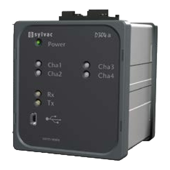
Messtasterpositionen geliefert werden können, mit einem Messbereich von +/-10V und einer Auflösung von bis zu 0,025mV. Die Module D304 und D304a verfügen über eine Erweiterung mit 4 Messtastern Im Folgenden bezeichnet D30Xy in der vorliegenden Anleitung immer ein Modul D302 oder D304 oder D302a oder D304a. 1.1 Vorderseite... -
Seite 25: Thermische Stabilisierung
2. Thermische Stabilisierung Die Module D30Xy sind mit einer internen Temperaturmessung ausgestattet. Beim Einschalten blinken die LEDs der Messtaster so lange, bis die Temperatur stabilisiert ist (ca. 10 Minuten ab einer Einschaltung des kalten Geräts). Mit dem Modul kann zwar direkt nach dem Einschalten gemessen werden, es wird jedoch empfohlen, nach der Stabilisierungsphase ein Preset vorzu- nehmen. -
Seite 26: Kalibrierung Für Die Messung Von Durchmessern
Kalibrierungsverfahren (Fortsetzung) • Für eine Kalibrierung mithilfe eines Endmaßes von 25mm senden Sie den Remote-Befehl CALi (i = Kanalnummer 1 bis4) • Für eine Kalibrierung mithilfe zweier beliebiger Endmasse senden Sie den Remote-Befehl CALi: Ref0, Ref1 (i = Kanalnummer 1bis 4; Ref0, Ref1 = Höhe der Endmasse, normalerwei- se Ref0 <... - Seite 27 Korrekturbeispiel 1) Taster P25 mit D30Xy ohne Korrektur -> maximale Abweichung von 1,4µm 2) Dasselbe Gerät mit einer Korrektur an 10 Punkten (alle 2,5mm) -> maximale Abweichung von 0,7µm Die Eingabe oder Änderung von Punkten erfolgt über Remote-Befehle (siehe COR, LCOR et NCOR).
-
Seite 28: Kalibrierung Eines Analogen Moduls (Nur D302A)
Verfahren zur Eingabe einer Punkt-für-Punkt-Korrektur (Die Remote-Befehle sind in Klammern angegeben) 1. Vorbereiten eines Satzes Endmasse oder eines geeigneten Kalibrierungsgeräts. 2. Setzen Sie das Modul in folgende Modi: Maximale Auflösung (RES1) Positive Messrichtung (CHA+) 3. Positionieren Sie den Taster auf ein Referenzmass und führen Sie eine Nullstellung durch (PRE). -
Seite 29: Funktion Min/Max/Delta
Status * < > Messung [mm] 0,95 * Ist Toleranz A geringer als die eingegebene Toleranz B (Messung des Innendurchmessers), so werden die Zeichen > und < umgekehrt. Wenn eine der 3 Funktionen Min/Max/Delta aktiv ist, entspricht die Anzeige also dem seit der letz- ten Nullstellung gemessenen Extremwert (die Ablehnungsanzeige hat Priorität vor der Wiederauf- nahmeanzeige, die ihrerseits Priorität vor der Toleranzanzeige OK hat). -
Seite 30: Analoge Ausgänge (Nur Modul D302A)
Die Module D30Xa verfügen für jeden der zwei Kanäle über je einen unabhängigen analogen Aus- gang.. Der Ausgangsspannungsbereich ist einstellbar zwischen -10V und +10V für beliebige Taster aus der Sylvac-Produktpalette (von 2 bis 50mm) mit einer Auflösung von 0,025mV. 8.1 Konfiguration der analogen Ausgänge (D30Xa) Mithilfe des Remote-Befehls AREF kann die Referenzspannung der für die Preset-Position des... -
Seite 31: Architektur
Adresse befinden. 11. Einspeisung der Module Das Ladegerät Sylvac 904.4000 ermöglicht die Versorgung von bis zu 4 über den Bus verbun- denen Modulen. Wenn +24VDC am Netzstecker verfügbar sind, können 8 Module an den Bus angeschlossen werden. Prüfen Sie immer, ob die Power-LED an allen Modulen grün leuchtet. -
Seite 32: Technische Spezifikation Des Moduls
0,1μm : 25/s (1 Kanal), 12/s (n Kanäle) 1μm : 35/s (1 Kanal), 20/s (n Kanäle) Personalisierter Ablesemodus bis zu 100/s (1 Kanal), 80/s (n Kanäle) Auflösung der analogen Ausgän- 0,025mV ge (nur D30Xa ) 13. Verpackungseinheit Siehe unser Katalog oder Website www.sylvac.ch... - Seite 33 Índice Descripción general Cara frontal Cara posterior Estabilización térmica Señalizaciones Indicador luminoso de Encendido Indicadores luminosos Palpadores Indicadores luminosos Rx / Tx Calibraciones Calibración del módulo Procedimiento de calibración Calibración para medición de diámetros Emparejamiento de un palpador y un módulo de conversión Calibración del módulo analógico (sólo D302a) Función tolerancias Función Mín./Máx./Delta...
-
Seite 34: Descripción General
1. Descripción general El módulo D302 permite la lectura y la conversión del valor de la posición de dos palpadores Sylvac con una resolución de hasta 0,1 µm. Los resultados están disponibles en un puerto USB y en un puerto MODBUS RS485. Sus numerosas funciones integradas permiten, además, resolver la mayor parte de los problemas de mediciones encontrados. -
Seite 35: Estabilización Térmica
2. Estabilización térmica Los módulos D30Xy están dotados de una medición interna de temperatura. Al encenderlo, los indicadores luminosos de los palpadores parpadean hasta que la temperatura se ha estabilizado (unos 10 minutos cuando se trata de encendido en frío). Si bien el módulo es apto para medir desde el momento en que es encendido, se recomienda hacer un Preset tras el período de esta- bilización. -
Seite 36: Calibración Para Medición De Diámetros
Procedimiento de calibración (continuación) • Para realizar una calibración mediante un calzo de 25 mm, enviar el mando remoto CALi (i = número del canal 1al 4) • Para realizar una calibración mediante dos calzos sea cuál sea su altura, enviar el mando remoto CALi: Ref0, Ref1 (i = número del canal 1 al 4;... - Seite 37 Ejemplo de corrección 1) Palpador P25 con D30Xy sin corrección -> error máximo de 1,4 µm 2) Mismo instrumento con una corrección en 10 puntos (cada 2,5 mm) -> error máximo de 0,7 µm La introducción o la modificación de los puntos se ha llevado a cabo mediante mandos remotos (véanse COR, LCOR y NCOR).
-
Seite 38: Calibración Del Módulo Analógico (Sólo D302A)
Procedimiento de introducción de una corrección punto por punto (Se detallan entre paréntesis los mandos remotos) 1. Preparar un juego de calzos de referencia o un instrumento de calibración apropiado. 2. Configurar el módulo de la forma siguiente: Resolución máxima (RES1) Dirección de medición positiva (CHA+) 3. -
Seite 39: Función Mín./Máx./Delta
Estatus * < > Medición [mm] 0,95 * Si la tolerancia A es inferior a la tolerancia B introducida (medición de diámetros interiores), entonces los signos > y < se invierten. Si una de las tres funciones Mín./Máx./Delta está activada, el signo corresponde al extremo que medir desde la última puesta a cero (el signo de rechazo tiene prioridad por encima del signo de recogida que, al su vez, tiene prioridad por encima del signo de tolerancia Bien). -
Seite 40: Salidas Analógicas (Sólo Módulo D302A)
El rango de tensión de salida puede ajustarse entre -10 V y +10 V para cualquier palpador de la gama Sylvac (de 2 a 50 mm) con una resolución de 0,025 mV. 8.1 Configuración de las salidas analógicas (D302a) Mediante el mando remoto AREF, definir la tensión de referencia correspondiente a la posición... -
Seite 41: Arquitectura
10.1 Arquitectura 10.2 Protocolo Modbus El protocolo MODBUS define el intercambio de datos entre el maestro y los módulos D302 escla- vos. Véase la tabla de transacciones Modbus y direcciones de las variables adjunta. 10.3 Configuración de la dirección Modbus del módulo De fábrica, los módulos D30Xy no cuentan con una dirección predefinida. -
Seite 42: Especificaciones Técnicas Del Módulo
IP 40 (de conformidad con las especificaciones IEC 60529) Peso D302y 0,3 kg Peso D304y 0.45kg Consumo D302y <150 mA en bloque cargador Sylvac (<1,5 W) Consumo D304y <250mA en bloque cargador Sylvac (<2.5W) Temperatura de almacenaje Entre –20°C y +45°C Temperatura de utilización Entre +5°C y +40°C... - Seite 43 Indice Descrizione generale Lato anteriore Lato posteriore Stabilizzazione termica Segnalazioni Led Accensione Led sensori Led Rx / Tx Tarature Calibrazione del modulo Procedura di calibrazione Calibrazione per la misurazione di diametri Accoppiamento di un sensore e di un modulo di conversione Calibrazione del modulo analogico (solo D302a) Funzione tolleranze Funzione Min/Max/Delta...
-
Seite 44: Descrizione Generale
1. Descrizione generale Il modulo D302 consente la lettura e la conversione del valore della posizione di due sensori Syl- vac fino ad una risoluzione di 0,1 µm. I risultati sono disponibili su una porta USB e su una porta MODBUS RS485. -
Seite 45: Stabilizzazione Termica
2. Stabilizzazione termica Les modules D30Xy sont pourvus d’une mesure interne de température. Al momento della mes- sa in tensione, i LED dei sensori lampeggiano fino a quando la temperatura non risulta stabilizzata (circa 10 minuti a partire da una messa in tensione a freddo). Nonostante il modulo sia indicato per misurare la messa in tensione, si consiglia di ripristinare un'impostazione predefinita Preset dopo il periodo di stabilizzazione. -
Seite 46: Calibrazione Per La Misurazione Di Diametri
Procedura calibrazione (segue) • Per una calibrazione con un spessore di 25 mm, inviare il comando a distanza CALi (i = numero del canale da 1 a 4). • Per una calibrazione con due spessori qualsiasi, inviare il comando a distanza CALi: Ref0, Ref1 (i = numero del canale da 1a 4 ;... - Seite 47 Esempio di correzione 1) Sensore P25 con D30Xy senza correzione -> errore massimo di 1,4µm 2) Même instrument avec une correction sur 10 points (tous les 2.5mm) -> erreur maximale de 0.7µm L'introduzione o la modifica dei punti è fatta con comandi a distanza (vedere COR, LCOR e NCOR).
-
Seite 48: Funzione Tolleranze
Procedura per introdurre una correzione punto per punto (I comandi a distanza sono indicati tra parentesi) 1. Preparare un set di spessori campione o uno strumento di taratura adeguato. 2. Metter il modulo nei seguenti modi: Risoluzione massima (RES1) Direzione misurazione positiva (CHA+) 3. -
Seite 49: Funzione Min/Max/Delta
Stato * < > Misurazione [mm] 0,95 * Se la tolleranza A è inferiore alla tolleranza B introdotta (misurazione diametri interni), allora i segni > e < vengono invertiti. Si l’une des 3 fonctions Min/Max/Delta est activée, le signe correspond alors à l’extrema mesuré depuis la dernière remise à... -
Seite 50: Uscite Analogiche (Moduli D30Xa Solamente)
Les modules D30Xa sont équipés d’une sortie analogique indépendante pour chacun des canaux. L'intervallo di tensione di uscita può essere regolato tra -10V e +10V per tutti i sensori della gam- ma Sylvac (da 2 a 50mm) con una risoluzione di 0,025mV. 8.1 Configurazione uscite analogiche (D30Xa) Con l'aiuto del comando a distanza AREF, definire la tensione di riferimento corrispondente nella posizione di Preset del sensore. -
Seite 51: Architettura
10.1 Architettura 10.2 Protocollo Modbus Lo scambio dei dati tra la matrice e i moduli D302 slave viene definito dal protocollo MODBUS. Vedere la tabella delle transazioni Modbus e gli indirizzi delle variabili in allegato. 10.3 Configurazione indirizzo Modbus del modulo I moduli D30Xy non hanno indirizzi predefiniti in fabbrica. -
Seite 52: Specifiche Tecniche Del Modulo
IP 40 (secondo specifiche IEC 60529) Peso D302y 0,3 kg Peso D304y 0.45kg Consumo D302y < 150 mA sul blocco caricatore Sylvac (<1,5 W) Consumo D304y < 250 mA sul blocco caricatore Sylvac (<2,5 W) Temperatura di immagazzinaggio Tra –20°C e +45°C Temperatura d'uso Tra +5°C e +40°C... -
Seite 53: Codes Für Fernbedienungen
A. Annexes A.1 Codes for remote commands Remote commands in bold are not dependant of the probes’ chanels (F selection code is not useful). Code Function Returns the measured value 1..4 Selects a channel to read ‘A’ A1..4 Selects the number of channels to read ACHA ? Returns the activation of the channels ACHA 0 or OFF... - Seite 54 Code Function COR 0 or OFF Disables the measuring correction COR 1 or ON Enables the measuring correction COR PP / Insert or modify a point of the correction. PP=Point Number [0…25]. +|- x.yyyyyy Max correction : 2.0mm/0.1’’ COR O? Returns the activation status of the point par point correction (ON, OFF) ‘D’...
- Seite 55 EXT X[:Y] Actives the mode of the external contact. X = function, Y = channels X = 1 : Print X = 2 : Zero setting X = 3 : Preset X = 4 : Preset then Print X = 5 : Reset of the Min/Max/Delta values X = 6 : Turns on/off the continuous data output X = 7 : Preset on Min value X = 8 : Preset on Max value...
- Seite 56 Returns the transmission speed of the RS485 port MBD ? MBD xxxxxx Changes the transmission speed of the RS485 port (4’800, 9’600, 19’200, 38’400, 56’000, 57’600, 76’800, 115’200, 128’000, 187’500, 230’400, 256’000 bds) default = 128’000 bds Activates the Min measuring mode MIN ? Returns the Min measured value (if any of the modes Min/Max/Delta is activated) Actives the millimeter unit...
- Seite 57 PRINT ? Returns status of all print options Option TXT : Adds spaces to align output values (default ON) Option XLS : Adds a space in front of signed values (default ON) Option SIGN : Replaces the + sign by a space (default ON) Option TAB : Adds a TAB between channels (default ON) Option SP :...
-
Seite 58: Com Port Usb, Übertragungsfehler
SUM ? Returns the user probes reading summation SUM xxx Modify the user probes reading summation (1...200) SYNF ? Returns the probe synchronization status (D304y only SYNF 0 or OFF Independant probe reading (default) SYNF 1 or ON Synchronized probe reading (D304y only) ‘T’... -
Seite 59: Modbus-Transaktionen
Response Modbus frame. The salve answer can be a correct answer or an Exception in case of error. For better data throughput, Sylvac modules always use the RTU transmission mode. For more details on Modbus protocol, refer to the MODBUS Application Protocol. - Seite 60 Table of supported D30Xy modbus functions Function code Description PDU request format PDU answer format 0x01 aaaa nnnn 0x01 bb ll Read n bits 0x02 aaaa nnnn 0x02 bb ll 0x03 aaaa nnnn 0x03 bb ll Read n registers 0x04 aaaa nnnn 0x04 bb ll Write 1 bit 0x05 aaaa yy00...
-
Seite 61: Adressen Der Modbus-Variablen
Table C at addresses 8000…9999. Two independent memory areas containing 10,000 addresses are overwritten for bit access or word access. Access to an address not defined by Sylvac returns an error. All the addresses are between 0 and 9999. -
Seite 62: Bit Speicherbereich
Access to a variable may be: • Read and write (R/W) • Read only (RO) • Write only (WO) • R/W* indicates that a variable can be read but always returns 0. • RO∆ indicates that the value can only be read once (reading causes the variable to be reset to zero) Access to a probe position variable while the probe is not connected returns the code -1 (not a number, NAN in the usual IEEE754 float format). -
Seite 63: Adressen Der Modbus-Variablen
User reset 9024 R/W* Factory reset 9025 R/W* 1s pulse on external contact 9026 R/W* Probe LEDs flash for 5 9027 R/W* seconds Configuration procedure starts (see Module Modbus 9536 0 to end the configuration procedure address configuration) A.5.2 Adresses of the Modbus word variables F32 means a Float value coded according to IEEE754. - Seite 64 64 bits formatted probe 0032 Formatted probe position (see below) position 64 bits formatted min. 0036 Formatted probe position (see below) value 64 bits formatted max. 0040 Formatted probe position (see below) value Access to bits 0000-0031 0056 2x16 See corresponding bits (probe A) Formatted Preset value 0060 Formatted probe position (see below)
- Seite 65 Point number for correc- 0360 0 .. max 25 tion pp access Formatted probe position (see below). A single access is allowed after Correction pp value 0362 writing the point number @ word address 0360 0 : No error 1 : Invalid point 2 : Invalid correction 4 : Non monotonic Last correction pp error...
- Seite 66 0: no error 1: Incorrect 32 bit access 2: Incorrect address 3: Inactive function Last module error 8117 4: Invalid value 5: Undefined probe 6: Empty variable 7: Invalid configuration 8: Protected variable 64 bits sum of probes 1 8148 Formatted probe position (see below) and 2 (P1 + P2) 64 bits difference of...
- Seite 67 8705 R(W) (Writing only possible by configuration procedure) Project number 8950 Type of module 8951 D302 or D304 or D302A or D304A Access to bits 9024-9535 9256 16x16 See corresponding bits Access to bits 9536-9791 9288 16x16 See corresponding bits...
-
Seite 68: Modbus Ausführungscodes
A.6 MODBUS exceptions codes Exception code Description Illegal function Illegal address Illegal data Slave failure Port RS-485, configuration parameters Baud rate 4’800…256’000 bds (transmission speed, default = 128'000 bds) Parity Even Data Bits Stop bits Flow Control None RS-485 bus load 1/32 (max 32 modules on the RS-485 bus link) A.7 Connectors functions Ground... -
Seite 69: Connector Block
RS 485 IN Negative Modbus signal (RS-485 B wire) Pin 1 Not used Pin 2 Not used Pin 3 Positive Modbus signal (RS-485 A wire) Pin 4 Ground (0 volt) Pin 5 Power supply 8..24VDC Pin 6 Not used Pin 7 External contact signal, negative RS-485 Pin 8 External contact signal, positive RS-485... -
Seite 70: Übersicht Und Befestigung
J1 and J2 contact of previous module With jumper, accepts the power supply from the previous module (Max 4 chained modules powered from one Sylvac charger, max 8 chained modules powered from +24VDC) With jumper, activates the line termination resistor (150 ohms) A.8 Overall and fixture... - Seite 71 NOTES ........................................................................................................................................................................................................................................................................................................................................................................................................................................................................................................................................................................................................................................................................................................................................................................................................................................................................................................................................................................................................................................
- Seite 72 Sous réserve de toute modification Änderungen vorbehalten Ch. du Closalet 16 Changes without prior notice CH - 1023 Crissier E-mail: vente@sylvac.ch Edition 2015/03 - Manuel D302y/D304y EFDIS www.sylvac.ch 681.286.02-100...