
Verwandte Anleitungen für Carrier AQUASMART 42Y


Inhaltszusammenfassung für Carrier AQUASMART 42Y
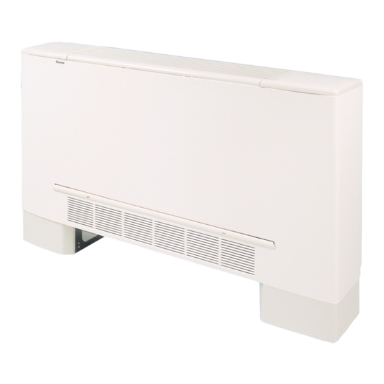
- Seite 1 AQUASMART FAN COIL UNITS Installation and maintenance VENTILCONVETTORI Installazione e manutenzione VENTILOCONVECTEURS Mise enplace et entretien RAUMKLIMATRUHEN Installation und Wartung...
-
Seite 2: Inhaltsverzeichnis
Per quanto riguarda la descrizione del funzionamento For description and operation of the “HSM” control, della regolazione “HSM” fare riferimento al manuale refer to Carrier instruction manual 18137-76. d'istruzione Carrier 18137-76. Contents Indice page pagina Comfort ............... - Seite 3 Wartungsverfahren für die Raumklimatruhe. maintenance des ventilo-convecteurs. Die Betriebsanleitung für den “HSM”-Regler ist dem Pour la description et le mode de fonctionnement de Carrier-Handbuch Nr. 38137-76 zu entnehmen. la régulation “HSM”, se référer à la notice d'instruction Carrier 28137-76. Inhalt Table des matières...
-
Seite 4: Installation
Installazione Installation Cabinet installation / Montaggio mobiletto / Assemblage du cabinet / Montage des Gehäuses Rear hooks Screws Filter Agganci posteriori Viti Filtro Crochets postérieurs Filtre Hintere Haken Schrauben Filter Ricevimento Receipt of unit Check that packaging is undamaged. Verificare l'integrità dell'imballo. Disimballare l'unità... - Seite 5 Installation Installation Work necessary on site for fresh air damper mounting (accessory) Lid removal Opere murarie per l’installazione della serranda aria esterna Rimozione coperchietto (accessorio) Levée du couvercle Travaux de maçonnerie pour l'installation du registre pour la prise d'air neuf (accessoire) Entfernung des Deckels Bauseitige Maßnahmen zur Installation der Frischluftklappe (Zubehör)
- Seite 6 Installazione Installation Wall-mounted vertical for consistency unit / Unità verticale sospesa a parete /Unité verticale au mur / Vertikales Wandgerät min. 500 min. Mod. 42Y 792 792 992 992 992 1192 1192 1392 1392 1592 332 332 532 532 532 732 932 1132 432 432 632 632 632 832 1032 1032 1232...
- Seite 7 Installation Installation Horizontal ceiling mounted unit / Unità orizzontale sospesa al soffitto / Unité horizontale fixée au plafond / Deckenmontiertes Horizontalgerät No 2 10x15 slots for wall N° 2 boutonnières 10x15 fastening pour la fixation au mur Drain connection 20 mm o. d. Drainage de l'eau de Auxiliary drain pan (optional) condensation ø...
-
Seite 8: Water Connections
Water connections Collegamenti idraulici Top view / Vista in pianta Front view / Vista frontale Vue en plan / Ansicht von oben Vue de front / Vorderansicht A Floor B Wall Pavimento Parete Paroi Fußboden Wand Collegamenti idraulici Water connections Le tubazioni dell'impianto idrico potranno arrivare sia da pavimento Water piping can enter either from the floor or from the wall, using the space shown in the figure. -
Seite 9: Connexions Hydrauliques
Wasseranschlüsse Connexions hydrauliques Panneau électrique Quadro elettrico Schalttafel Electric panel No. 2 vis No. 2 screw No. 2 vite Schraube Nr. 2 Piton Hook Gancio Haken No. 1 vis No. 1 screws No. 1 viti Schrauben Nr. 1 Capteur Sensor Sensore Sensor Languettes en caoutchouc... -
Seite 10: Electric Connections
Collegamenti elettrici Electric connections HY-NEC board Terminal block Valve terminal block HY-NEC board (Prime) Terminal block (power supply) Scheda HY-NEC Morsettiera Morsettiera valvole Scheda HY-NEC (Prime) Morsettiera alimentazione elettrica Carte HY-NEC Borne Borne soupape Carte HY-NEC (Premières) Borne d'alimentation Karte HY-NEC Klemmleiste Ventil-Klemmbrett Karte HY-NEC (Prime) -
Seite 11: Connexions Électriques
Connexions électriques Elektrische Anschlüsse ³ Centrifugal fan · Tangential fan Current drawn/Corrente assorbita/Intensité absorbé/Stromaufnahme Available only with centrifugal fan Mod. 42Y Low capacity High capacity A Current drawn W Power input ³ 0.11 0.15 0.23 0.28 0.32 0.49 0.54 0.53 0.61 0.82 ³... - Seite 12 Electric connections Collegamenti elettrici Electrical box 2/4 pipes + Electric heaters Legend: Quadro elettrico 2/4 tubi + Riscaldatori elettrici Tableau de distribution électrique 2/4 tubes + Réchauffeurs électriques HY-NEC board (Prime) Transformer Schalttafel 2/4 Rohre + Elektroheizungen HY-NEC board Air/water jumper Terminal block Electrical power supply terminal block...
- Seite 13 Elektrische Anschlüsse Connexions électriques Electrical box 2/4 pipes Legend: Quadro elettrico 2/4 tubi HY-NEC board (Prime) Tableau de distribution électrique 2/4 tubes Transformer Schalttafel 2/4 Rohre HY-NEC board Air/water jumper Terminal block Electrical power supply terminal block Cable clamp Valve terminal block Motor connector TO EARTH SCREW Legenda:...
-
Seite 14: Maintenance
Maintenance Manutenzione Filter removal / Rimozione filtro / Démontagedu filtre / Entfernung des Filters Cabinet unit Unità a mobiletto Unité carrosseée Gerät mit Gehäuse Checks before starting Controlli prima dell'avviamento Unit shall not be started until all system piping has been cleaned L'unità... -
Seite 15: Wartung
Entretien Wartung Filter removal / Rimozione filtro / Démontagedu filtre / Entfernung des Filters Concealed unit Unità da incasso Unité à encastrer Einbaugerät Prüfungen vor der ersten Inbetriebnahme Contrôles à effectuer avant la mise en marche Das Gerät darf nicht in Betrieb genommen werden, ehe die Nettoyer et purger les tuyaux du système avant la mise en marche de l’unité. -
Seite 16: Accessories
Accessories – Accessori – Accessoires – Zubehör Support feet and cover panels Vertical drain pan Support feet Sostegni e zoccoli Sostegni Bacinella ausiliaria verticale Pieds de support et socles Bac auxiliaire vertical Pieds de support Stützfüße Stützfüße und Fußleisten Vertikale Ablaufwanne Horizontal drain pan Fresh air damper Return air grille... - Seite 17 Accessories – Accessori – Accessoires – Zubehör Part no. - Codice Sizes / Grandezze / Dimensions / Größen Code - Teil Nr. 42X9X22 42E9X25 42X9X05V 42X9X04H 42E9X50 -1 42E9X50 - 3 42E9X50 - 6 42E9X50 - 8 42E9X50 -X 42X9X02 - 1 42X9X02 - 3 42X9X02 - 6 42X9X02 - 8...
-
Seite 18: Unit Designation
Unit designation – Identificazione dell'unità – Désignation – Geräte-Bezeichnung – Coil Valves Series Unit type Size Version Control Electric heater F =controller with V = w/val. without drain pan 1 = 01 M = cabinet S = standard, 230V F = 2-pipe left –... -
Seite 19: Regolatore Hsm
HSM system / Sistema HSM Système HSM / HSM-System THE SYSTEM / IL SISTEMA / LE SYSTÈME / DAS SYSTEM CCN bus 32 Zones - 128 Terminals / 32 Zone - 128 Terminali 32 Zone - 128 Terminals / 32 Zonen - 128 Endverschlüsse A Building Management A Building Management A Building Management... -
Seite 20: Hsm Controller
Communicating HSM control system Sistema di regolazione comunicante HSM HSM controller Regolatore HSM Régulator HSM HSM-Regler Introduzione Introduction The regulation system is comprised of two boards - HY-NEC and Il sistema di regolazione è composto da due schede HY-NEC e HY-NEC (Prime), a room unit “CRC”... -
Seite 21: Einleitung
Kommunizierendes HSM Régulation communicante HSM Regelsystem Unit control panel Pannello di controllo Microterminal domotique Geräte- Regeltafel Einleitung Introduction Das Regelsystem besteht aus zwei Karten (HY-NEC und HY-NEC Le système de régulation est composé de deux cartes HY-NEC et - Prime), einem Raumgerät “CRC” (auf Wunsch) und aus Ventilen HY-NEC (Premières), d’une unité... -
Seite 22: Room Controller
Room Controller Room Controller Functions Funzioni Display Display Temperature increase button Tasto aumento della temperatura Tasto diminuzione della temperatura Temperature decrease button Tasto per la selezione della velocità del ventilatore Fan speed selection button Tasto per la selezione della modalità di funzionamento Operating mode selection button Factory configurations Configurazioni di fabbrica... - Seite 23 Room Controller Room Controller Fonctions Funktionen Display Display Touche d’augmentation de la température Taste zur Temperaturerhöhung Touche de diminution de la température Taste zur Temperatursenkung Taste zur Wahl der Ventilatorgeschwindigkeit Touche pour la sélection de la vitesse du ventilateur Taste zur Wahl der Betriebsweisen Touche pour la sélection des modalités de fonctionnement Werkseitige Konfigurationen Configurations d’usine...
- Seite 24 Room Controller Room Controller Configurazione tramite CRC Configuration using the CRC La configurazione del sistema può essere eseguita sia dal System The system can be configured both by System Manager Manager che dal CRC (interfaccia utente) se montato. and by the CRC (user interface) if fitted. Con il CRC è...
- Seite 25 Room Controller Room Controller Configuration par l’intermédiaire de CRC Konfiguration mittels CRC La configuration du système peut aussi bien être effectuée par le Die Systemkonfiguration kann sowohl mit dem System Manager als auch System Manager que par le CRC (interface usager) s’il est monté. mit der CRC (Benutzer-Zwischenstelle), wenn diese montiert ist, erfolgen.
-
Seite 26: Problems And Solutions
Problems and solutions Problemi e soluzioni Symptom / Possible cause / / Solution Sintomo / Possibile causa / / Soluzione CHECK TO MAKE CONTROLLO DA EFFETTUARE - The display does not work (CRC). - Non funziona il display (CRC). - 12V - GND Signal power supply cable connection incorrect. - Collegamento errato dei cavi di alimentazione 12V - GND SIGNAL. -
Seite 27: Probleme Und Lösungen
Problèmes et solutions. Probleme und Lösungen Symptôme / Cause possible / / Solution Symptom / Mögliche Ursache / / Lösung CONTRÔLE À EFFECTUER DURCHZUFÜHRENDE ONTROLLE - Le display ne fonctionne pas (CRC). - Das Display (CRC) funktioniert nicht. - Erreur de branchement des câbles d’alimentation 12V – GND - Falsche Verbindung der 12V-Versorgungskabel - Erde-Signal SIGNAL. -
Seite 28: Wiring Diagrams
HSM wiring diagram 2/4-Pipe version Schema elettrico HSM versione 2/4-Tubi Schéma électrique HSM version 2/4 tubes Schaltplan HSM Version mit 2/4 Rohren Y / G J11B J11A MAIN BOARD HY-NEC J1-PCB TRACE +12V BOARD Y / G 2 3 4 5 6 11 12 13 14 TB 2... - Seite 29 Legend: Wire colours Factory wiring ATTENTION: Wiring by others Any warranty is declined in case of field A Brown FC Fan motor capacitor changes of factory wiring and settings. B Blue IFM Fan motor C Black MTB Power supply terminal block G Grey S1 Air sensor D Light blue...
- Seite 30 HSM wiring diagram 2/4 Pipe version + electric heater Schema elettrico HSM versione 2/4 Tubi + resistenza elettrica Schéma électrique HSM version 2/4 tubes + résistance électrique Schaltplan HSM Version mit 2/4 Rohren + Elektroheizung Y / G J11B J11A MAIN BOARD HY-NEC Y / G...
- Seite 31 Legend: Factory wiring Wire colours Wiring by others ATTENTION: EHT Heater relay Any warranty is declined in case of field A Brown F1 Fuse changes of factory wiring and settings. B Blue FC Fan motor capacitor HR Electric heater C Black IFM Fan motor G Grey MTB Power supply terminal block...
- Seite 32 L010125H25 - 1201 Via R. Sanzio, 9 - 20058 Villasanta (MI) Italy - Tel. 039/3636.1 The manufacturer reserves the right to change any product specifications without notice. La cura costante per il miglioramento del prodotto può comportare senza preavviso, cambiamenti o modifiche a quanto descritto. La recherche permanente de perfectionnement du produit peut nécessiter des modifications ou changements, sans préavis.