Gaspardo ALITALIA Gebrauch Und Wartung
Vorschau ausblenden
Andere Handbücher für ALITALIA:
- Gebrauchsanleitung (41 Seiten) ,
- Gebrauch und wartung (160 Seiten) ,
- Gebrauch und wartung (160 Seiten)
Inhaltsverzeichnis
Werbung
Verfügbare Sprachen
Verfügbare Sprachen
Quicklinks
Werbung
Inhaltsverzeichnis

Verwandte Anleitungen für Gaspardo ALITALIA


Inhaltszusammenfassung für Gaspardo ALITALIA
- Seite 1 MASCHIO GASPARDO S.p.A. ALITALIA USO E MANUTENZIONE USE AND MAINTENANCE GEBRAUCH UND WARTUNG EMPLOI ET ENTRETIEN *) Valido per Paesi UE *) Valid for EU member countries *) Valable dans les Pays UE Cod. G19503391 *) Gilt für EU-Mitgliedsländer 2014-12...
-
Seite 2: Inhaltsverzeichnis
ITALIANO ENGLISH INDICE INDEX Premessa ................ 5 Introduction ..............43 Generalità ................. 5 General ................43 Garanzia ................8 Guarantee ..............46 1.2.1 Scadenza garanzia ............8 1.2.1 Expiry of guarantee ............46 Identifi cazione dell’attrezzatura ........8 Identifi cation ..............46 Indicazioni generali di sicurezza ........ - Seite 3 DEUTSCH FRANÇAIS INHALT TABLES DE MATIERES Vorwort ................81 Introduction ..............119 Allgemeines ..............81 Généralités ..............119 Garantie ................. 84 Garantie ............... 122 1.2.1 Verfall des Garantieanspruchs ........84 1.2.1 Expiration de la garantie ..........122 Identifi zierung ..............84 Identifi cation ..............122 Allgemeine Sicherheitsanweisungen ......
- Seite 4 cod. G19503391...
-
Seite 5: Premessa
ITALIANO 1.0 PREMESSA Il presente Manuale delle istruzioni per l’uso (di seguito chiamato Manuale) fornisce all’utilizzatore informazioni utili per lavorare corret- tamente ed in sicurezza, facilitandolo nell’utilizzo della SEMINATRICE. L’utilizzo della macchina combinata (Erpice rotante - Seminatrice) defi nisce il presente manuale come parte integrante del manuale Uso e Manutenzione dell’erpice rotante. -
Seite 6: Personale Qualificato
ITALIANO USO E MANUTENZIONE Defi nizioni: Di seguito vengono fornite le defi nizioni dei principali termini utilizzati nel Manuale. Se ne consiglia un’accurata lettura prima della fruizione del Manuale. • OPERATORE: ..........La, o le persone, incaricate di installare, di far funzionare, di regolare, di eseguire la manutenzione, di pulire, di riparare e di trasportare una macchina. - Seite 7 ITALIANO USO E MANUTENZIONE Sintesi dei dispositivi di protezione individuale (DPI) da utilizzare durante tutte le fasi di vita della macchina Nella Tabella 1 vengono riassunti i DPI (Dispositivi di Protezione Individuale) da utilizzare durante le varie fasi di vita della macchina (ad ogni fase esiste l’obbligo dell’uso e/o la messa a disposizione del DPI).
-
Seite 8: Garanzia
ITALIANO USO E MANUTENZIONE 1.2 GARANZIA La garanzia ha validità di un anno, contro ogni difetto dei materiali, dalla data di consegna dell’attrezzatura. Verifi care all’atto della consegna che la macchina non abbia subito danni durante il trasporto e che gli accessori siano integri e al completo. -
Seite 9: Indicazioni Generali Di Sicurezza
ITALIANO USO E MANUTENZIONE 2.0 INDICAZIONI GENERALI DI SICUREZZA 2.1 SEGNALI DI SICUREZZA E INDICAZIONE 6) Pericolo di intrappolamento. State lontani dagli organi in movimento. 7) Pericolo di schiacciamento agli arti superiori durante la movi- I segnali descritti sono riportati sulla macchina (Fig. 2). Tenerli puliti mentazione di parti mobili. -
Seite 10: Norme Di Sicurezza E Prevenzione Infortuni
ITALIANO USO E MANUTENZIONE 2.2 NORME DI SICUREZZA E PREVENZIONE Norme generali 1) Durante il periodo di utilizzo, manutenzione, riparazione, mo- INFORTUNI vimentazione o immagazzinamento della macchina, utilizzare gli idonei dispositivi di protezione individuale. Fare attenzione al segnale di pericolo riportato nei vari capitoli 2) Qualsiasi lavoro di manutenzione, regolazione e pulizia va di questo manuale. - Seite 11 ITALIANO USO E MANUTENZIONE 25) Prima di mettere in funzione l’attrezzatura controllare che i Circolazione su strada piedini di sostegno siano stati tolti da sotto la seminatrice; 1) Per la circolazione su strada, è necessario attenersi alle nor- controllare che la seminatrice sia stata correttamente montata mative del codice stradale in vigore nel relativo Paese.
- Seite 12 ITALIANO USO E MANUTENZIONE Sicurezza relativa all’idraulica Manutenzione in sicurezza Durante le operazioni di lavoro e manutenzione, utiliz- 1) Al momento dell’allacciamento dei tubi idraulici all’impianto zare gli idonei dispositivi di protezione individuale (es.): idraulico del trattore, fare attenzione che gli impianti idraulici della macchina operatrice e della trattrice non siano in pres- sione.
-
Seite 13: Descrizione Della Seminatrice
• il rispetto di tutte le indicazioni del presente manuale; • l’esecuzione delle operazioni di ispezione e di manutenzione riportate nel presente manuale; • l’uso esclusivo di ricambi originali GASPARDO. È possibile percorrere e seminare/distribuire superfi ci con una pendenza fi no al 10%. -
Seite 14: Dati Tecnici
ITALIANO USO E MANUTENZIONE 3.1 DATI TECNICI ALITALIA ALITALIA PERFECTA U.M. Larghezza di trasporto 3,05 3,55 4,05 3,00 3,50 4,00 Larghezza di lavoro 3,00 3,50 4,00 3,00 3,50 4,00 Velocità di lavoro [Km/h] 8 (max) 8 (max) 8 (max) 8 (max) -
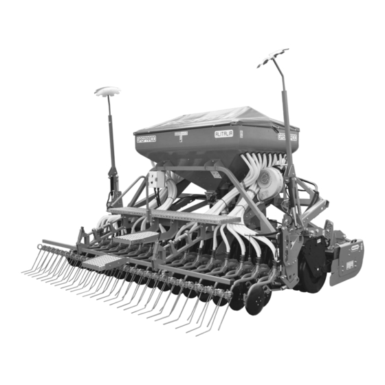
Seite 15: Disegno Complessivo
ITALIANO USO E MANUTENZIONE 3.2 DISEGNO COMPLESSIVO (Fig. 5) 9 Comando segnafi le oleodinamico; 1 Tramoggia semi; 10 Disco segnafi le; 2 Soffi ante; 11 Rullo dosatore per sementi NORMALI; 3 Assolcatore a stivaletto; 12 Rullo dosatore per sementi PICCOLE; 4 Assolcatore a disco (COREX);... -
Seite 16: Movimentazione
SOLLEVAMENTO DELLA SOLA SEMINATRICE (Fig. 6) Le lunghezze indicate delle cinghie sono solo indicative. Regolare la lunghezza delle cinghie per livellare la macchina durante il sollevamento. fi g. 6 Model (cm) (cm) ALITALIA 300 ALITALIA 350 ALITALIA 400 16 - IT cod. G19503391... - Seite 17 Le lunghezze indicate delle cinghie sono solo indicative. Regolare la lunghezza delle cinghie per livellare la macchina durante il sollevamento. Model (cm) (cm) ALITALIA 300 fi g. 7 ALITALIA 350 ALITALIA 400 ATTENZIONE • I materiali d’imballo (pallet, cartoni, ecc.) vanno smaltiti come previsto dalle normative vigenti, tramite le ditte autorizzate.
-
Seite 18: Completamento Macchina
ITALIANO USO E MANUTENZIONE 3.4 COMPLETAMENTO MACCHINA Per motivi d’ingombro possono essere fornite macchine con gruppi staccati, comunque contenuti e fi ssati nello stesso imballo: kit luci e tabelle d’ingombro, erpice copriseme posteriore. Curare il montaggio seguendo le indicazioni sotto riportate rispettando i valori delle coppie di serraggio delle viti a corredo, come indicato in Tabella 2 a pag. - Seite 19 ITALIANO USO E MANUTENZIONE SUPPORTO REGOLAZIONE PROFONDITÀ DI LAVORO (Fig. 11) Rimuovere le barre gialle (1) ed assemblare il supporto regolazione di profondità di lavoro nei punti (2). Fig. 11 MONTAGGIO RUOTINO POSTERIORE PER BARRA SEMINA PERFECTA 1) Accoppiare la seminatrice all’erpice rotante secondo le indicazioni riportate nel capitolo 4.1, facendo attenzione alla perpendicolarità...
-
Seite 20: Norme D'uso
4.1.2 PREDISPOSIZIONE DELL’ATTREZZATURA Predisporre l’erpice rotante per l’aggancio alla seminatrice, mon- tando le boccole in dotazione negli appositi attacchi (X, Fig, 13). Nelle versioni ALITALIA 350 e 400 predisporre l’attrezzatura con i supporti centrali (Y, Fig. 13). 20 - IT... -
Seite 21: Aggancio Della Seminatrice All'attrezzatura
ITALIANO USO E MANUTENZIONE 4.1.3 AGGANCIO DELLA SEMINATRICE ALL’ATTREZZATURA PERICOLO L’applicazione della seminatrice all’attrezzatura è una fase molto pericolosa. Fare molta attenzione ad effettuare l’intera operazione seguendo le istruzioni. L’operazione deve essere eseguita su un piano orizzontale, con la seminatrice posta sui piedi di parcheggio. 1) Agganciare l’erpice rotante alla trattrice secondo le indicazioni della Ditta Costruttrice. -
Seite 22: Sgancio Della Seminatrice Dall'attrezzatura
5) Agganciare il tirante superiore (G, Fig. 18/1) tra seminatrice fi g. 18/1 ed erpice rotante, regolando la lunghezza (L) secondo il rullo posteriore utilizzato (Tabella 4): Rullo ALITALIA ALITALIA Perfecta (M90B..) L (mm) pos. G L (mm) pos. G... -
Seite 23: Stabilità In Trasporto Attrezzatura Combinata-Trattore
ITALIANO USO E MANUTENZIONE 4.2 STABILITÀ IN TRASPORTO ATTREZZATURA 4.3 TRASPORTO STRADALE COMBINATA-TRATTORE Se si rendesse necessario trasportare la macchina su di un lungo percorso, questa può essere caricata sia su vagoni ferroviari che Quando una seminatrice viene accoppiata al trattore, divenendo su autocarri. -
Seite 24: Dosatore
ITALIANO USO E MANUTENZIONE 4.4 DOSATORE Il dosatore (Fig, 21), organo principale per il funzionamento dell’at- trezzatura, è posizionato sotto la tramoggia della semente. Riceve il moto da un motore elettrico collegato al sensore di velocità della trattrice. Per l’azionamento del dosaggio, la regolazione, il controllo e le prove di dosaggio, riferirsi al Libretto Uso e Manutenzione del Controllo Elettrico della Distribuzione. - Seite 25 ITALIANO USO E MANUTENZIONE Vengono forniti in dotazione alla macchina tre tipi di rulli dosatori: fi g. 24 rossi: 5 elementi, 8 camere per ruota, (mod. G1000) (A Fig. 24). verdi: 5 elementi, 16 camere per ruota (mod. N500) (A Fig. 24). gialli: 5 elementi, 32 camere per ruota, (rullo dosatore sementi fi...
- Seite 26 ITALIANO USO E MANUTENZIONE TASTATORE Anche il gruppo dei tastatori può essere facilmente smontato in pochi minuti, per effettuare operazioni di pulizia. Esso è composto da 5 portine indipendenti, controllate da molle regolabili. I separatori fi ssati tra una portina e l’altra permettono di azionare ogni singolo elemento in modo indipendentemente. Inoltre la forma stessa dei separatori offre uno scudo contro i corpi estranei che potrebbero danneggiare il rullo dosatore.
- Seite 27 ITALIANO USO E MANUTENZIONE SMONTAGGIO DELL’ASSE AGITATORE L’agitatore viene montato e smontato dal suo alloggiamento senza l’utilizzo di attrezzi, al fi ne di agevolare le operazioni di pulizia o sostituzioni di parti danneggiate. 1) Dosatore con gruppo tastatori e rullo dosatore smontati (Fig. 36). 2) Estrarre tutte le spille curvate dall’asse agitatore (Fig.
- Seite 28 ITALIANO USO E MANUTENZIONE ELEMENTI ELASTICI PULENTI Gli elementi elastici pulenti (A, Fig. 44) vengono usati con il rullo dosatore di colore giallo (mod. F25-125) durante la distribuzione di semi oleosi. L’azione principale degli elementi elastici è quella di mantenere libere le camere del rullo dosatore, garantendo una regolare e costante distribuzione.
-
Seite 29: Prova Di Dosaggio
ITALIANO USO E MANUTENZIONE DISTRIBUZIONE SEMENTI FINI 4.4.1 PROVA DI DOSAGGIO Prima di effettuare la prova di dosaggio, accertarsi che non Distribuzione di quantità inferiori a 3 kg/ha. siano presenti corpi estranei all’interno della tramoggia e del Durante la prova di dosaggio, per il ridotto numero di giri del cambio dosatore. -
Seite 30: Azionamento Della Soffi Ante
ITALIANO USO E MANUTENZIONE 4.5 AZIONAMENTO DELLA SOFFIANTE AZIONAMENTO OLEODINAMICO DELLA SOFFIANTE Norme di Sicurezza La soffi ante è una degli organi principali per ottenere una distribu- L’attrezzatura è idonea esclusivamente per l’impiego indicato. zione ottimale delle sementi. Ogni altro uso diverso da quello descritto in queste istruzioni Dopo la prima fase della distribuzione, in cui la selezione della può... - Seite 31 ITALIANO USO E MANUTENZIONE Descrizione del funzionamento Regolazione del soffi aggio: La velocità di rotazione del motore oleodinamico e quindi della La portata d’aria può e deve essere modifi cata in funzione del peso soffi ante è proporzionale alla pressione del fl usso visualizzata dal specifi...
-
Seite 32: Regolazione Della Profondità Di Semina
ITALIANO USO E MANUTENZIONE 4.6 REGOLAZIONE DELLA PROFONDITÀ DI SEMINA 4.6.1 ALITALIA Per una buona emergenza dei germogli è importante collocare il seme alla giusta profondità nel letto di semina. Assolcatori a stivaletto, assolcatori a disco COREX La profondità di semina viene regolata, contemporaneamente... - Seite 33 Per una buona emergenza dei germogli è importante collocare il seme alla giusta profondità nel letto di semina. Nella versione ALITALIA PERFECTA è stato introdotto un sistema che permette di gestire in modo indipendente il controllo della profondità di semina e della regolazione della pressione a terra degli elementi di semina.
-
Seite 34: Segnafi Le
ITALIANO USO E MANUTENZIONE 4.7 SEGNAFILE Il segnafi le è un dispositivo che traccia una linea di riferimento sul terreno, parallela al tragitto del trattore. Quando il trattore avrà terminato la corsa e invertito la marcia, si procederà correndo sulla linea di riferimento con il centro della trattrice (L, Fig. - Seite 35 ITALIANO USO E MANUTENZIONE L’impianto oleodinamico è integrato con regolatori di fl usso unidi- rezionali (Fig. 65) che permettono di regolare la quantità d’olio, in apertura od in chiusura secondo il senso di montaggio degli stessi. - Flusso da B a C libero (Fig. 65); - Flusso da C a B strozzato (regolato) (Fig.
-
Seite 36: Erpice Copriseme Posteriore A Molle
ITALIANO USO E MANUTENZIONE 4.8 ERPICE COPRISEME POSTERIORE A MOLLE La normale posizione di lavoro dell’erpice copriseme posteriore è indicata in Figura 68. In questa posizione, l’usura dei denti è uniforme tra quello corto e quello lungo. Agendo sulla maniglia di regolazione (I) è possibile modifi... -
Seite 37: Tramoggia
ITALIANO USO E MANUTENZIONE 4.9 TRAMOGGIA 4.10 PEDANA DI CARICO La tramoggia ha una capacità di carico minima di 1500 litri ed una L’utilizzo della pedana di carico (ed ispezione della tramoggia massima di 2000 litri se dotata di rialzo tramoggia (accessorio). Fig. -
Seite 38: Durante Il Lavoro
ITALIANO USO E MANUTENZIONE 4.13 DURANTE IL LAVORO La seminatrice è studiata per consentire una elevata velocità di PERICOLO semina, compatibilmente con tipo e superfi cie del terreno. È im- La seminatrice può trasportare sostanze chimiche conciate portante ricordare che variando la velocità del trattore non si varia con il seme. -
Seite 39: Manutenzione
ITALIANO USO E MANUTENZIONE 5.0 MANUTENZIONE IMPIANTI ELETTRICI - Prima di qualsiasi operazione, staccare l’alimentazione dal cir- cuito elettrico. Sono di seguito elencate le varie operazioni di manutenzione da eseguirsi con periodicità. Il minor costo di esercizio ed una lunga IMPIANTI OLEODINAMICI durata della macchina dipende, tra l’altro, dalla metodica e costante - Interventi di manutenzione sugli impianti oleodinamici de-... -
Seite 40: A Macchina Nuova
ITALIANO USO E MANUTENZIONE 5.1 PIANO DI MANUTENZIONE - Tabella Riassuntiva PERIODO INTERVENTO A MACCHINA NUOVA - Ingrassare tutti i punti contrassegnati dalla decalcomania n° 14 (“GRASE”) a pag. 9 di questo manuale. - Dopo le prime otto ore di lavoro, controllare il serraggio di tutte le viti. - Verifi... -
Seite 41: Demolizione E Smaltimento
ITALIANO USO E MANUTENZIONE 6.0 DEMOLIZIONE E SMALTIMENTO Operazione da eseguirsi a cura del Cliente. Prima di effettuare la demolizione della macchina, si raccomanda di verifi care attentamente lo stato fi sico della stessa, valutando che non ci siano parti della struttura eventualmente soggette a possibili cedimenti strutturali o rotture in fase di demolizione. Il Cliente dovrà... - Seite 42 cod. G19503391...
-
Seite 43: Introduction
ENGLISH 1.0 INTRODUCTION This Instruction Manual for Operation (hereafter called “the Manual”) provides the operator with useful information on how to simplify SEED DRILL use by operating it correctly and in safe conditions. The use of the combined machine (Rotating Harrow - Seed Drill) defi nes this manual as an integral part of the Operation and Mainte- nance Manual of the rotating harrow. -
Seite 44: Qualified Personnel
ENGLISH USE AND MAINTENANCE Defi nitions: Below is a list of defi nitions of the main terminology used in this Manual. Read these defi nitions carefully before consulting the Ma- nual. • OPERATOR: ..........The person/s charged with installing, starting up, adjusting, carrying out maintenance, cleaning, repairing or transporting a machine. - Seite 45 ENGLISH USE AND MAINTENANCE List of personal protection equipment (PPE) to be used during all the phases of the machine life Table 1 summarises the PPE (Personal Protection Equipment) to be used during the different phases of machine life (each phase requires mandatory use of and/or availability of PPE.
-
Seite 46: Guarantee
ENGLISH USE AND MAINTENANCE 1.2 GUARANTEE The guarantee is valid for a year, against all defects of material, from the date of delivery of the equipment. On delivery, check that the equipment has not been damaged during transport and that the accessories are integral and complete. POSSIBLE CLAIMS MUST BE PRESENTED IN WRITING WITHIN EIGHT DAYS OF RECEIPT. -
Seite 47: General Safety Rules
ENGLISH USE AND MAINTENANCE 2.0 GENERAL SAFETY RULES 2.1 DANGER AND INDICATOR SIGNALS The signs described are reproduced on the machine (Fig. 2). Keep 6) Danger of getting trapped. Keep away from moving parts. them clean and replace them if they should come off or become 7) Danger of crushing of the upper limbs while handling mobile illegible. -
Seite 48: Safety Regulations And Accident Prevention
ENGLISH USE AND MAINTENANCE 2.2 SAFETY REGULATIONS AND ACCIDENT General norms 1) During machine operation, maintenance, repair, handling and PREVENTION storage, wear suitable personal protection equipment. 2) Maintenance, adjustment and cleaning operations must be Pay attention to danger signs, where shown, in this booklet. carried out after positioning the machine on the ground (in stable conditions);... - Seite 49 ENGLISH USE AND MAINTENANCE 26) Before releasing the equipment from the third point attachment, Transport on Road put the hoist command lever into the locked position and lower 1) When driving on public roads, be sure to follow the highway the support feet.
- Seite 50 ENGLISH USE AND MAINTENANCE Safety measures concerning the hydraulics Maintenance in safety During work and maintenance operations, use suitable per- 1) At the moment of connecting the hydraulic tubes to the hydraulic system of the tractor, make sure that the hydraulic sonal protection gear: systems of the operating machine and the tractor are not under pressure.
-
Seite 51: Description Of The Seeder
• compliance with all the instructions provided in this manual; • performance of inspection and maintenance operations described in this manual; • exclusive use of genuine GASPARDO spare parts. The machine can to sow on a gradient up to 10%. -
Seite 52: Technical Data
ENGLISH USE AND MAINTENANCE 3.1 TECHNICAL DATA ALITALIA ALITALIA PERFECTA U.M. Transport width 3,05 3,55 4,05 3,00 3,50 4,00 Work width 3,00 3,50 4,00 3,00 3,50 4,00 Working speed [Km/h] 8 (max) 8 (max) 8 (max) 8 (max) 8 (max) 8 (max) Max. -
Seite 53: Assembly Drawing
ENGLISH USE AND MAINTENANCE 3.2 ASSEMBLY DRAWING (Fig. 5) 9 Hydraulic system row marker; 1 Seed hopper; 10 Row marker disk; 2 Fan; 11 Dosing roller for STANDARD seeds 3 Suffolk coulters; 12 Dosing roller for FINE seeds; 4 Disk coulters (COREX); 13 Adjustment seed covering harrow;... -
Seite 54: Handling
The belt lengths shown are merely for indication. Adjust the length of the belts to make the machine level during lifting operations. fi g. 6 Model (cm) (cm) ALITALIA 300 ALITALIA 350 ALITALIA 400 54 - EN cod. G19503391... - Seite 55 The belt lengths shown are merely for indication. Adjust the length of the belts to make the machine level during lifting operations. Model (cm) (cm) ALITALIA 300 fi g. 7 ALITALIA 350 ALITALIA 400 ATTENTION • Packaging materials (pallets, cartons, etc.) must be disposed of as prescribed by the existing regulations through authorised disposal companies.
-
Seite 56: Completion Of The Machine
ENGLISH USE AND MAINTENANCE 3.4 COMPLETION OF THE MACHINE If the assembled machine is too large, some units may be disassembled from the machine. These units, which are placed inside the same package, are the lights kit and warning boards, the rear seed-covering harrow. Install these parts as instructed below and tighten the supplied screws according to the tightening torques indicated, as shown in Table 2 on page 48. - Seite 57 ENGLISH USE AND MAINTENANCE DEPTH ADJUSTMENT SUPPORT (Fig. 11) Remove yellow bar (1) and to assembly depth adjustment support in the points (2) before use. Fig. 11 REAR WHEEL ASSEMBLY FOR PERFECTA SEEDING BAR 1) Following the indications in chapter 4.1, combine the seed drill with the rotary harrow, with attention to its perpendicularity (90°).
-
Seite 58: Rules Of Use
4.1.2 EQUIPMENT ARRANGEMENT Arrange the rotating harrow for connection to the seeder: install the supplied bushings in the connections (Fig. 13). In ALITALIA 350 and 400, confi gure the equipment with the central supports (Y, Fig. 13). 58 - EN... -
Seite 59: Seeder Hooking To The Equipment
ENGLISH USE AND MAINTENANCE 4.1.3 SEEDER HOOKING TO THE EQUIPMENT DANGER Hooking up the seeder to the equipment is a very dangerous phase. Be very careful in following the instructions for the whole operation. The operation must be carried out on a horizontal plane, with the seeder resting on its parking feet. -
Seite 60: Unhitching The Planting Unit From The Equipment
5) Hook the upper tie-rod (G, Fig. 18/1) between seeder and ro- fi g. 18/1 tating harrow, by adjusting the length (L) according to the rear roller utilized (Table 4): Roller ALITALIA ALITALIA Perfecta (M90B..) L (mm) pos. G L (mm) pos. G... -
Seite 61: Stability Of Planting Unit And Tractor During Transport
ENGLISH USE AND MAINTENANCE 4.2 STABILITY OF PLANTING UNIT AND TRACTOR 4.3 TRANSPORT DURING TRANSPORT If it becomes necessary to transport the machine for a long distance, it can be loaded onto a railway wagon or a truck. For this purpose, When a planting unit is coupled to a tractor, so becoming an integral consult «Technical Data»... -
Seite 62: Doser
ENGLISH USE AND MAINTENANCE 4.4 DOSER The doser (Fig. 21) the most important part for distribution, is located underneath the seed hopper. It is driven by an electric motor connected to the tractor speed sensor. In that event, for the metering operation and the metering adjustment, checking and tests, please refer to the relevant User and Maintenance Booklet. - Seite 63 ENGLISH USE AND MAINTENANCE There are various types of wheels for a wide range of applications, fi g. 24 in three different product families (Fig. 24): red: 5 elements, 8 chambers per wheel, (mod. G1000) (A); green: 5 elements, 16 chambers per wheel, (mod. N500) (B); yellow: 5 elements, 32 chambers per wheel, (fi...
- Seite 64 ENGLISH USE AND MAINTENANCE FEELER PIN The feeler unit may also be easily disassembled in a single block in a matter of minutes for cleaning purposes. It consists of 5 single hatches that are spring-loaded to ensure tight closing. The hatches do not touch the seeding wheel while it is in operation! Thanks to the separators fi...
- Seite 65 ENGLISH USE AND MAINTENANCE DISASSEMBLING THE AGITATOR AXLE The agitator can be removed from its housing without the use of tools, with a view to facilitating cleaning operations and replacing damaged parts. 1) Doser with seed hatch and seeding wheel disassembled (Fig. 36). 2) Remove the various parts of the agitator (Fig.
- Seite 66 ENGLISH USE AND MAINTENANCE CLEANING SPRING ELEMENTS Cleaning spring elements (A, Fig. 44) are used during the distri- bution of oily seeds by means of the yellow seeding roller, mod. F25-125. The main action of these spring elements is keeping the chambers of the seeding roller clear so that seed distribution is regular and constant.
-
Seite 67: Dosing Test
ENGLISH USE AND MAINTENANCE 4.4.1 DOSING TEST DISTRIBUTION OF FINE SEEDS Distribution of quantities lower than 3 kg/ha. Adjust the doser with the unit on the ground, the motor turned off and the tractor blocked in place. Before carrying out the During the dosing test the number of gearbox revolutions is low dosing test, make sure there are no foreign bodies inside the because the quantity of product to be distributed is small. -
Seite 68: Blower Drive
ENGLISH USE AND MAINTENANCE 4.5 BLOWER DRIVE OLEO-DYNAMIC BLOWER DRIVE Safety The blower is one of the main parts of the machine and enables The equipment is suitable only for the use indicated. Any use optimised seed distribution. other than that described in these instructions can cause After the fi... - Seite 69 ENGLISH USE AND MAINTENANCE Working description Blower pump control: The rotational speed of the oleo-dynamic motor, and therefore that The air capacity can and must be changed according to the specifi c of the blower, is proportional to the fl ow pressure shown on the weight of the seeds: manometer (Table 4).
-
Seite 70: Adjusting The Seeding Depth
ENGLISH USE AND MAINTENANCE 4.6 ADJUSTING THE SEEDING DEPTH 4.6.1 ALITALIA To obtain a good level at which sprouts come out, the seed needs to be placed at the right depth into the seeding bed. Hoe coulter, disc coulter COREX... - Seite 71 The seed must be placed at the right depth in the seed bed for good surfacing of the buds. A system has been introduced in the ALITALIA PERFECTA version that allows to independently manage the seeding depth control and the ground’s pressure adjustment of the seeding elements.
-
Seite 72: Row Marker Disk Adjustment
ENGLISH USE AND MAINTENANCE 4.7 ROW MARKER DISK ADJUSTMENT The row marker is a machine that traces a reference line parallel to the tracks of the tractor on the ground. Once the tractor has completed its run and it has turned around, follow the reference row with one of the centre of the tractor (L, Fig. - Seite 73 ENGLISH USE AND MAINTENANCE The hydraulic systems provided come equipped with one-way fl ow regulators (Fig. 65) which allow for the regulation of the quantity of oil during opening or closing, depending on how the regulators have been installed: Flow from B to C, free (Fig. 65); Flow from C to B, choked (regulated) (Fig.
-
Seite 74: Rear Covering Harrow
ENGLISH USE AND MAINTENANCE 4.8 REAR COVERING HARROW The normal working position of the harrow is shown in Figure 68. In this position, the wear on the teeth, between the long and the short one is even and uniform. By adjusting the regulating handle (I), it is possible to change the angle of the harrow. -
Seite 75: Hopper
ENGLISH USE AND MAINTENANCE 4.9 HOPPER 4.10 LOADING PLATFORM The hopper has a minimum load capacity of 1500 litres and a ma- Use of the loading (or hopper inspection Fig. 72) platform is only ximum of load capacity 2000 litres when equipped with a hopper consented when the planting unit is at a stand still, the wheels extension (accessory). -
Seite 76: During Work
ENGLISH USE AND MAINTENANCE 4.13 DURING WORK The seeder has been studied to allow a high sowing speed, com- DANGER patible with the type and surface of the ground. The seeder can transport treated chemical substances toge- Bear in mind that a variation in tractor speed does not lead to a ther with the seed. -
Seite 77: Maintenance
ENGLISH USE AND MAINTENANCE 5.0 MAINTENANCE HYDRAULIC SYSTEMS - Hydraulic systems must be maintained exclusively by skilled operators. Here follows a list of various maintenance operations to be carri- - The hydraulic system is under high pressure; because of ed out periodically. Lowered operating costs and a longer lasting the accident risk, when searching for leakage points special seeding machine depend, among others, on the methodical and auxiliary instruments should be used. -
Seite 78: When The Machine Ls New
ENGLISH USE AND MAINTENANCE 5.1 MAINTENANCE PLAN - Summary table INTERVAL TYPE OF WORK WHEN THE MACHINE lS NEW - Grease all parts indicated by transfer nr. 14 (‘GRASE’) at page 47 of this leafl et. - After the fi rst hours of work check that all the bolts are still tight. - Check the tightness of the bolts on the seed coulters. -
Seite 79: Demolition And Disposal
ENGLISH USE AND MAINTENANCE 6.0 DEMOLITION AND DISPOSAL This operation is to be carried out by the customer. Before demolishing the machine, you are advised to carefully check its physical condition and ascertain whether there are any parts of the structure that may be susceptible to structural collapse or breakage during demolition. The customer should operate in compliance with the environment protection laws in force in his/her country. - Seite 80 cod. G19503391...
-
Seite 81: Vorwort
DEUTSCH 1.0 VORWORT Die vorliegende Bedienungsanleitung (nachstehend Handbuch genannt) liefert dem Benutzer nützliche Informationen für eine korrekte und sichere Arbeit, und erleichtert ihm den Gebrauch der Sämaschine. Der Gebrauch der Kombinationsmaschine (Kreiselegge - Sämaschine) wird in diesem Handbuch als ergänzendes Teil des Gebrauchs- und Wartungshandbuchs der Kreiselegge defi... -
Seite 82: Schutzabdeckung
DEUTSCH GEBRAUCH UND WARTUNG Defi nitionen: Nachstehend werden die Defi nitionen der wichtigsten der in diesem Handbuch verwendeten Ausdrücke aufgeführt. Wir empfehlen, sie vor der Verwendung des Handbuchs aufmerksam zu lesen. • BEDIENUNGSPERSONAL: ......Die Person oder die Personen, die mit der Installation, dem Betrieb, der Einstellung, der Wartung, der Reinigung, der Reparatur und dem Transport der Maschine beauftragt sind. - Seite 83 DEUTSCH GEBRAUCH UND WARTUNG Übersicht über die während aller Lebensphasen der Maschine zu benutzende persönliche Schutzausrüstung (PSA) In Tabelle 1 werden die verschiedenen Arten der PSA (Persönliche Schutzausrüstung) zusammengefasst, die in den einzelnen Leben- sphasen der Maschine zu verwenden sind (in jeder Phase besteht die Pfl icht zum Gebrauch bzw. zur Bereitstellung der PSA). Die Verantwortung für die Ermittlung und die Auswahl der angemessenen und geeigneten Art und Klasse der Schutzausrüstung liegt beim Kunden.
-
Seite 84: Garantie
DEUTSCH GEBRAUCH UND WARTUNG 1.2 GARANTIE Die Garantie erstreckt sich auf ein Jahr ab Lieferdatum des Geräts gegen jeglichen Materialfehler. Bei Auslieferung sicherstellen, daß das Gerät keine Transportschäden aufweist und das Zubehör unbeschädigt und vollständig ist. ETWAIGE REKLAMATIONEN SIND SCHRIFTLICH INNERHALB BINNEN 8 TAGEN AB DEM ERHALT BEIM VERTRAGSHÄN- DLER. -
Seite 85: Allgemeine Sicherheitsanweisungen
DEUTSCH GEBRAUCH UND WARTUNG 2.0 ALLGEMEINE SICHERHEITSANWEISUNGEN 2.1 WARNSIGNALE UND ANZEIGESIGNALE 6) Einfanggefahr. Von laufenden Teilen Abstand halten. 7) Quetschgefahr bei Verschliessen. Nicht in der Reichweite der Die beschriebenen Signale sind an der Maschine angebracht (Abb. Maschine stehenbleiben. 2). Sauber halten und wechseln, falls sie abfallen oder unleserlich 8) Mitschleppgefahr. -
Seite 86: Sicherheits- Und Unfallverhütungs-Bestimmungen
DEUTSCH GEBRAUCH UND WARTUNG 2.2 SICHERHEITS- UND UNFALLVERHÜTUNGS- Allgemeine Vorschriften 1) Beim Gebrauch, der Wartung, der Reparatur oder der Einla- BESTIMMUNGEN gerung der Maschine eine angemessene persönliche Schut- zausrüstung tragen. Das Gefahrsignals in diesem Heft besonders beachten. 2) Sämtliche Wartungs-, Einstell- und Reinigungsarbeiten dürfen nur bei auf dem Boden stehender Maschine (Maschine muss stabil stehen), abgeschaltetem Antrieb, ausgeschaltetem Motor Die Gefahrsignale haben drei Niveaus:... - Seite 87 DEUTSCH GEBRAUCH UND WARTUNG Teilnahme am Straßenverkehr 24) Nie den Fahrerplatz verlassen, wenn der Schlepper in Betrieb 1) Bei der Teilnahme am Straßenverkehr sind die Bestimmungen ist. der Straßen-verkehrsordnung zu beachten, die in dem jewei- 25) Vor der Inbetriebnahme des Geräts prüfen, daß die Stützfüsse ligen Land gelten.
- Seite 88 DEUTSCH GEBRAUCH UND WARTUNG Sicherheitsmaßnahmen bezüglich des Hydrauliksystems Sichere Wartung Bei der Arbeit und der Wartung sind geeignete individuelle 1) Beim Anschließen der Hydraulikschläuche an die Hydraulikan- Schutzmittel anzuwenden: lage des Schleppers ist darauf zu achten, dass die Hydrauli- kanlagen der Ausrüstung und des Schleppers nicht unter Druck stehen.
-
Seite 89: Beschreibung Der Sämaschine
• die Einhaltung aller im vorliegenden Handbuch enthaltenen Angaben; • die Ausführungen der Inspektions- und Wartungstätigkeiten, die in diesem Handbuch aufgeführt sind; • die ausschließliche Verwendung von Original-Ersatzteilen von GASPARDO. Es ist möglich, auf Flächen zu säen, die ein Gefälle aufweisen von bis zu 10 %. -
Seite 90: Technische Daten
DEUTSCH GEBRAUCH UND WARTUNG 3.1 TECHNISCHE DATEN ALITALIA ALITALIA PERFECTA U.M. Transportbreite 3,05 3,55 4,05 3,00 3,50 4,00 Arbeitsbretie 3,00 3,50 4,00 3,00 3,50 4,00 Arbeitsgang [Km/h] 8 (max) 8 (max) 8 (max) 8 (max) 8 (max) 8 (max) Reihenanzahl [nr.]... -
Seite 91: Zusammenfassend
DEUTSCH GEBRAUCH UND WARTUNG 3.2 ZUSAMMENFASSEND (Fig. 5) Mechanischen Spurreißer; Saatkasten; 10 Spurreißerscheibe; Gebläse; 11 Dosierrolle für NORMALES Saatgut Säbelschar; 12 Dosierrolle für KLEINES Saatgut; Scheibenschar (COREX); 13 Saatstriegel mit Einstellung; Einfache Scheibenschar; 14 Saatstriegel; Scheibenschar DDS (PERFECTA); 15 Beladeplattform mit Aufstieg; Dreipunktanschluß... -
Seite 92: Fortbewegung
ANHEBEN NUR DER SÄMASCHINE (Abb. 6) Die angegebenen Gurtlängen dienen nur als Anhaltspunkt. Die Länge der Traggurte so regulieren, dass die Maschine beim Anheben genau waagerecht ist. fi g. 6 Model (cm) (cm) ALITALIA 300 ALITALIA 350 ALITALIA 400 92 - DE cod. G19503391... - Seite 93 Die angegebenen Gurtlängen dienen nur als Anhaltspunkt. Die Länge der Traggurte so regulieren, dass die Maschine beim Anheben genau waagerecht ist. Model (cm) (cm) ALITALIA 300 fi g. 7 ALITALIA 350 ALITALIA 400 ACHTUNG • Das Verpackungsmaterial (Palette, Kartons usw.) muss entsprechend den geltenden Bestimmungen von autorisierten Un- ternehmen entsorgt werden.
-
Seite 94: Ergänzender Ausbau Der Maschine
DEUTSCH GEBRAUCH UND WARTUNG 3.4 ERGÄNZENDER AUSBAU DER MASCHINE Aus Platzgründen können die Maschinen in nicht zusammengebauten Einheiten geliefert werden, welche jedoch in jedem Fall in dersel- ben Verpackung enthalten sind: Lampenset und Maßtabellen (optional), hintere Saatgutabdeckegge. Entsprechend den untenstehenden Angaben montieren, und dabei die Anzugsdrehmomente der mitgelieferten Schrauben laut Tabelle 2 auf Seite 84 berücksichtigen. -
Seite 95: Halter Für Arbeitstiefeeinstellung (Fig. 11)
DEUTSCH GEBRAUCH UND WARTUNG HALTER FÜR ARBEITSTIEFEEINSTELLUNG (Fig. 11) Die gelben Stangen (1) entfernen und der Halter für Arbeitstiefeeinstellung in den Punkten (2) montieren. Fig. 11 MONTAGE DER HINTEREN ROLLEN FÜR DIE SAATSTANGE PERFECTA 1) Die Sämaschine an die Kreiselegge kuppeln, wie in den Anweisungen im Kapitel 4.1 angegeben, dabei auf lotrechte Position derselben achten (90°). -
Seite 96: Betriebs-Anleitungen
Die Kreiselegge für das Ankoppeln an die Sämaschine vorbereiten; dazu die mitgelieferten Buchsen in die entsprechenden Halterun- gen einsetzen (Abb. 13). Bei den Ausführungen ALITALIA 350 und 400 Geräte mit mittigen Halterungen vorsehen (Y, Abb. 13). 96 - DE... -
Seite 97: Kupplung Der Sämaschine An Die Ausrüstung
DEUTSCH GEBRAUCH UND WARTUNG 4.1.3 KUPPLUNG DER SÄMASCHINE AN DIE AUSRÜSTUNG GEFAHR Bei der Montage der Sämaschine an die Landwirtschafts- maschine ist mit äußerster Vorsicht vorzugehen. Bei der Ausführung dieser Arbeit sehr vorsichtig sein und die Anlei- tungen befolgen. Der Anschluß hat ausschließlich auf einer horizontalen Fläche und mit auf die Stützbeine abgestellter Sämaschine durchgeführt zu werden. -
Seite 98: Abkuppeln Sämaschine-Ausrüstung
5) Die obere Spannstange (G, Abb. 18/1) zwischen die Sämaschi- fi g. 18/1 ne und die Drehegge anklinken und die Länge (L) regulieren, gemäss der hinteren Ackerwalze benutzt (Tabelle 4): Walze ALITALIA ALITALIA Perfecta (M90B..) L (mm) pos. G L (mm) pos. G... -
Seite 99: Stabilität Von Sämaschine-Schlepper Beim Transport
DEUTSCH GEBRAUCH UND WARTUNG 4 . 2 S TA B I L I T Ä T V O N S Ä M A S C H I N E - 4.3 TRANSPORT Sollte sich ein Transport der Maschine über längere Strecken als nötig SCHLEPPER BEIM TRANSPORT erweisen, so kann diese sowohl auf einen Transportwagon oder einen Wenn eine Sämaschine an den Schlepper angekuppelt wird, und... -
Seite 100: Dosier
DEUTSCH GEBRAUCH UND WARTUNG 4.4 DOSIERVORRICHTUNG Der Dosierer (Abb. 21) ist die wichtigste Vorrichtung für den Betrieb die Sämaschine und ist unter dem Saatgutbehälter (Düngerbehäl- ter) angebracht. Wird durch einen an den Geschwindigkeitssensor des Schlep- pers angeschlossenen Elektromotor angetrieben. Gegebenfalls ist für die Dosierung, die Einstellung, die Steue- rung und die Dosierproben Bezug auf die entsprechende Bedie- nungsund Wartungsanleitung zu nehmen. - Seite 101 DEUTSCH GEBRAUCH UND WARTUNG Standardraeder sind doppelt versetzt ausgefuehrt, es existieren fi g. 24 mehrere Raeder fuer verschiedenste Verwendung in 3 Familien (Abb. 24): Rot: 5-teilig, 8 Kammern pro Rad, (mod. G1000) (A). Grün: 5-teilig, 16 Kammern pro Rad, (mod. N500) (B). Gelb: 5-teilig, 32 Kammern pro Rad, (Feindosierrad) (mod.
- Seite 102 DEUTSCH GEBRAUCH UND WARTUNG ABTASTER Auch die Bodenklappe kann zur Reinigung als komplette Baugruppe in wenigen Minuten ausgebaut werden. Sie besteht aus 5 ein- zelnen Klappen mit einer fest eingestellten Vorspannkraft durch Federdruck. Die Bodenklappen beruehren das Saerad im Betrieb nicht! Zwischen den Klappen sind feststehende Zwischenwaende angeordnet, die ein unabhaengiges Arbeiten der einzelnen Klappen ermoeglichen.
-
Seite 103: Ausbau Der Ruehrwelle
DEUTSCH GEBRAUCH UND WARTUNG AUSBAU DER RUEHRWELLE Die Ruehrwelle kann werkzeuglos aus dem Gehauese entnommen werden um Reini- gungsarbeiten zu erleichtern oder beschaedigte Teile zu ersetzen. 1) Dosiergeraet mit ausgebauter Bodenklappe und demontiertem Saerad (Abb. 36). 2) Alle Ruehrelemente aus der Ruehrwelle ziehen (Abb. 37). 3) Ruehrwelle (Abb. - Seite 104 DEUTSCH GEBRAUCH UND WARTUNG REINIGUNGSWELLE Die Reinigungsfedern zur Saeuberung des Zellenrades (A, Fig. 44) werden benutzt wenn die Gefahr der Oelbildung des Saatgutes (z.B. Raps) besteht. Sinnvoll ist der Einsatz nur beim Feinsaerad F25-125 (gelb). Die Reinigungswelle befi ndet sich ausserhalb des Dosierbereiches und kann somit jederzeit dur Sichtkontrolle auf Verschleiss und Funktionueberprueft werden.
-
Seite 105: Dosierprüfung
DEUTSCH GEBRAUCH UND WARTUNG STREUUNG FEINES SAATGUT 4.4.1 DOSIERPRÜFUNG Streuung einer unter 3 kg/ha liegenden Saatgutmenge. Vor der Ausführung des Dosierungstests ist sicherzustellen, dass keine Fremdkörper im Trichter und Dosierer vorhanden Bei der Abdrehprobe kann es aufgrund der an die geringe au- sind. -
Seite 106: Antrieb Des Gebläses
DEUTSCH GEBRAUCH UND WARTUNG 4.5 ANTRIEB DES GEBLÄSES HYDRAULISCHER ANTRIEB DES GEBLÄSES Sicherheit Das Gebläse ist eines der wichtigsten Organe für eine optimale Das Gerät ist ausschließlich für die hier beschriebene Verwen- Saatgutstreuung. dung vorgesehen. Jeder sonstige, von den Angaben dieser Nach der ersten Verteilungsphase, in der die auszustreuende Betriebsanleitung abweichende Gebrauch kann die Maschine Saatgutmenge mittels des Dosierers dosiert wird, ist in der zweiten... - Seite 107 DEUTSCH GEBRAUCH UND WARTUNG Beschreibung der Funktionsweise Druckeinstellung: Die Drehzahl des Hydromotors und damit also des Gebläses ist Der Luftdurchsatz kann auf der Basis des spezifischen direkt proportional vom Öldruck abhängig, der am Manometer Saatgutgewichts eingestellt werden: ablesbar ist (Tabelle 4). Ein Sicherheitsventil auf der Hydrauli- kanlage sorgt dafür, daß...
-
Seite 108: Einstellung Der Aussaattiefe
DEUTSCH GEBRAUCH UND WARTUNG 4.6 EINSTELLUNG DER AUSSAATTIEFE 4.6.1 ALITALIA Für ein korrektes Keinem des Saatgutes ist es wichtig, daß das Saatgut mit der richtigen Tiefe im Saatbeet ausgesät wird. Schleppschar und Scheibenschar COREX Die Aussaattiefe wird mit hydraulischer Regelung gleichzeitig für alle Scharren eingestellt, üben die Scharren mittels der Zugfedern... - Seite 109 Für eine gute Entwicklung der Triebe ist es wichtig, dass die Saat in richtiger Tiefe im Saatbett abgelegt wird. In der Ausführung ALITALIA PERFECTA wurde ein System ein- geführt, das es ermöglicht, auf unabhängige Weise die Kontrolle der Saattiefe und die Einstellung des Drucks auf die Erde der Saatelemente zu steuern.
-
Seite 110: Spurreisser
DEUTSCH GEBRAUCH UND WARTUNG 4.7 SPURREISSER Der Spurreisser ist eine Vorrichtung, die eine parallel zum Schlep- perlauf liegende Bezugslinie auf dem Boden zieht. Wenn der Traktor den Lauf beendet und gewendet hat, fährt man mit der Traktormitte (L, Abb. 62) auf der Richtlinie, je nach benutztem Spurreißer. Bei jedem neuen Durchlauf muß... -
Seite 111: Einstellung Des Spurreisserarms
DEUTSCH GEBRAUCH UND WARTUNG Die mitgelieferten öldynamischen Anlagen sind mit Flußreglern (Abb. 65) ausgestattet, die eine Einstellung der Ölmenge beim Öffnen oder Schließen je nach Montagerichtung derselben ermöglichen: Fluß von B nach C frei (Abb. 65); Fluß von C nach B gedrosselt (eingestellt) (Abb. 65). Die Feststellnutmutter (1) lockern und den Drehknopf (2) zwecks Einstellung drehen. -
Seite 112: Rückwärtige Egge Mit Federung
DEUTSCH GEBRAUCH UND WARTUNG 4.8 RÜCKWÄRTIGE EGGE MIT FEDERUNG Die normale Arbeitsposition der Egge wird auf Abb. 68 illustriert. In dieser Position ist der Verschleiß der kurzen und langen Zähne gleichförmig. Durch Einwirken auf die Einstellkurbel (I) kann die Neigung der Egge verändert werden. Der Arbeitsdruck der Federzähne der Saatgutabdeckegge kann durch Drehung der Feder (L) auf dem oberen Parallelarm verändert werden (Abb. -
Seite 113: Trichter
DEUTSCH GEBRAUCH UND WARTUNG 4.9 SAATGUTBEHÄLTER 4.10 LADETRITTBRETT Der Saatgutbehälter verfügt über ein Fassungsvermögen von min- Der Gebrauch des zum Beladen (und zur Trichterinspektion Abb. destens 1500 Litern und maximal 2000 Litern, wenn er mit einem 72) dienenden Trittbrettes ist nur bei stehender Sämaschine Saatgutbehälter-Aufsatz (Zubehör) ausgestattet ist. -
Seite 114: Während Des Betriebs
DEUTSCH GEBRAUCH UND WARTUNG 4.13 WÄHREND DES BETRIEBS Die Sämaschine wurde derart geplant, um ein optimales Aussäen GEFAHR des Saatguts im Verhältnis zu den gegebenen Bodenverhältnissen Die Sämaschine kann chemische Substanzen, die mit dem zu gewährleisten. Es ist zu beachten, daß durch Veränderung der Samen vermischt sind, transportieren. -
Seite 115: Wartung
DEUTSCH GEBRAUCH UND WARTUNG 5.0 WARTUNG ÖLHYDRAULISCHE ANLAGEN - Wartungsarbeiten auf den ölhydraulischen Anlagen dürfen nur von geschultem Personal ausgeführt werden. Hier folgend sind die verschiedenen, regelmässig auszuführenden - Falls von der Teilnahme auf der Hydraulikanlage, den hydro- Wartung-sarbeiten aufgeführt. Die geringeren Betriebskosten und statischen Druck leeren, der alle hydraulischen Kommandos die lange Lebensdauer des Geräts hängen unteranderem von der in allen Positionen einige Male, trägt den Motor nachher... -
Seite 116: Bei Neuer Maschine
DEUTSCH GEBRAUCH UND WARTUNG 5.1 WARTUNGSPLAN - Übersichtstabelle ZEITRAUM TÄTIGKEIT BEI NEUER MASCHINE - Dem Abziehbild Nr. 14 (“GREASE”) auf Seite 85 dieses Heftes gekennzeichneten Schmier- punkte zu schmieren. - Nach den ersten acht Betriebsstunden den Anzug aller Schrauben prufen. - Den Anzug der Mutterschrauben der Säscharenreisser überprüfen. -
Seite 117: Zerlegen Und Entsorgen Der Maschine
DEUTSCH GEBRAUCH UND WARTUNG 6.0 ZERLEGEN UND ENTSORGEN DER MASCHINE Für das Zerlegen und Entsorgen der Maschine hat der Kunde zu sorgen. Vor dem Verschrotten der Maschine ist der Zustand der Ma- schine genau zu überprüfen und sicherzustellen, dass keine Gerüstteile vorhanden sind, die beim Zerlegen auseinanderbrechen oder nachgeben könnten. - Seite 118 cod. G19503391...
-
Seite 119: Introduction
FRANÇAIS 1.0 INTRODUCTION Le présent Manuel d’utilisation (ci-après appelé Manuel) fournit à l’utilisateur des informations utiles pour travailler correctement et en toute sécurité, et lui faciliter l’utilisation du SEMOIR. L’utilisation de la machine combinée (Herse rotative - Semoir) défi nit le présent Manuel comme partie intégrante du Manuel d’Utilisation et d’Entretien de la herse rotative. -
Seite 120: Emploi Et Entretien
FRANÇAIS EMPLOI ET ENTRETIEN Défi nitions: Ci-dessous sont fournies les défi nitions des principaux termes utilisés dans le Manuel. Il est conseillé de les lire attentivement avant d’utiliser le Manuel. • OPÉRATEUR: ..........La ou les personnes chargées d’installer, de faire fonctionner, de régler, d’effectuer l’en- tretien, de nettoyer, de réparer et de transporter une machine. - Seite 121 FRANÇAIS EMPLOI ET ENTRETIEN Synthèse des équipements de protection individuelle (EPI) à utiliser pendant toutes les phases de vie de la machine. Le Tableau 1 résume les EPI (Équipements de Protection Individuelle) à utiliser lors des différentes phases de la vie de la machine (à chaque phase, l’utilisation et/ou la mise à...
-
Seite 122: Garantie
FRANÇAIS EMPLOI ET ENTRETIEN 1.2 GARANTIE La garantie est valable pour un an contre tout défaut du matériel, à partir de la date de livraison de l’équipement. Au moment de la livraison de votre machine vérifi ez si elle n’a pas été endommagée pendant le transport et si tous les accessoires sont en bon état. -
Seite 123: Indications Générales De Sécurité
FRANÇAIS EMPLOI ET ENTRETIEN 2.0 INDICATIONS GÉNÉRALES DE SÉCURITÉ 2.1 SIGNAUX DE SECURITE D’INDICATION 7) Risque d’écrasement. Ne vous approchez pas du rayon d’action de la machine. Les signaux décrits sont indiqués sur la machine (Fig. 2). Nettoyer 8) Danger d’enroulement. Ne pas retirer les protections avec la et remplacer ces signaux s’ils sont détachés ou illisibles. -
Seite 124: Normes De Securite Et De Prevention Des Accidents
FRANÇAIS EMPLOI ET ENTRETIEN 2.2 NORMES DE SECURITE ET DE PREVENTION Normes générales 1) Pendant la période d’utilisation, d’entretien, de déplacement DES ACCIDENTS ou de stockage de la machine, utiliser les équipements de protection individuelle adaptés. Faire attention au signal de danger quand il apparaît dans 2) Tout travail d’entretien, réglage et nettoyage doit être effectué... - Seite 125 FRANÇAIS EMPLOI ET ENTRETIEN Circulation sur route 24) Ne pas quitter le poste de conduite quand le tracteur est en marche. 1) Pour la circulation routière, il faut respecter les normes du 25) Avant la mise en marche de l’équipement, contrôler que les code de la route en vigueur dans le pays en question.
- Seite 126 FRANÇAIS EMPLOI ET ENTRETIEN Mesures de sécurité concernant la commande hydraulique Entretien en conditions de securite Pendant les opérations de travail et de maintenance, tiliser les 1) Au moment du raccordement des tubes hydrauliques à l’instal- dispositifs adéquats de protection individuelle : lation hydraulique du tracteur, s’assurer que les installations hydrauliques de la machine agricole et du tracteur ne sont pas sous pression.
-
Seite 127: Description De La Machine
• le respect de toutes les indications du présent manuel; • l’exécution des opérations d’inspection et d’entretien fi gurant dans le présent manuel; • l’utilisation exclusive des pièces de rechange originales GASPARDO. Il est possible de semer des surfaces dont la pente va jusqu’à 10%. -
Seite 128: Donnees Techniques
FRANÇAIS EMPLOI ET ENTRETIEN 3.1 DONNEES TECHNIQUES ALITALIA ALITALIA PERFECTA U.M. Largeur de transport 3,05 3,55 4,05 3,00 3,50 4,00 Largeur de travail 3,00 3,50 4,00 3,00 3,50 4,00 Vitesse de travail [Km/h] 8 (max) 8 (max) 8 (max) 8 (max) -
Seite 129: Dessin Global
FRANÇAIS EMPLOI ET ENTRETIEN 3.2 DESSIN GLOBAL (Fig. 5) 9 Levier de commande traceur; 1 Trémie; 10 Disque traceur; 2 Souffl erie; 11 Rouleau doseur pour semences NORMALES; 3 Soc à sabot; 12 Rouleau doseur pour semences PETITES; 4 Sols à disque (COREX); 13 Réglages herse de recouvrement;... -
Seite 130: Movimentation
Les longueurs des courroies indiquées sont purement indicatives. Régler la longueur des courroies pour mettre la machine à niveau pendant son soulèvement. fi g. 6 Model (cm) (cm) ALITALIA 300 ALITALIA 350 ALITALIA 400 130 - FR cod. G19503391... - Seite 131 Les longueurs des courroies indiquées sont purement indicatives. Régler la longueur des courroies pour mettre la machine à niveau pendant son soulèvement. Model (cm) (cm) ALITALIA 300 fi g. 7 ALITALIA 350 ALITALIA 400 ATTENTION • Les matériaux d’emballage (palette, cartons, etc.) doivent être éliminé conformément aux normes en vigueur, en faisant appel aux sociétés autorisées.
-
Seite 132: Montage De La Machine
FRANÇAIS EMPLOI ET ENTRETIEN 3.4 MONTAGE DE LA MACHINE Pour des impératifs d’encombrement, certaines machines peuvent être fournies avec des groupes détachés, contenus néanmoins dans le même emballage: kit éclairage et tableaux de grandes dimensions (en option), herse de recouvrement arrière. Réaliser le montage en suivant les indications reportées ci-dessous en respectant les valeurs des couples de serrage des vis fournies, tel qu’indiqué... - Seite 133 FRANÇAIS EMPLOI ET ENTRETIEN SUPPORT RÉGULATION PROFONDEUR DE TRAVAIL (Fig. 11) Enlevez les barres jaunes (1) et assembler le support régulation de profondeur de travail dans les points (2) avant emploi. Fig. 11 MONTAGE DE LA ROUE ARRIERE POUR BARRE DE SEMIS PERFECTA 1) Coupler le semoir à...
-
Seite 134: Normes D'emploi
4.1.2 PRÉDISPOSITION DE L’ ÉQUIPEMENT Préparer la herse rotative pour l’accrochage au semoir, en montant les douilles fournies dans les attelages prévus à cet effet (Fig. 13). Dans les versions ALITALIA 350 et 400 prédisposer l’outillage avec les supports centraux (Y, Fig. 13). ... -
Seite 135: Accrochage Du Semoir À L'équipement
FRANÇAIS EMPLOI ET ENTRETIEN 4.1.3 ACCROCHAGE DU SEMOIR À L’ÉQUIPEMENT DANGER L’assemblage du semoir à la machine est une phase trés dangereuse. Faire bien attention et respecter les instructions. L’opération doit être effectuée sur un plan horizontal, avec le semoir placé... -
Seite 136: Detelage Du Semoir - Equipement
5) Accrocher le tringle supérieur (G, Fig. 18/1) entre le semoir et fi g. 18/1 la herse rotative, en réglant la longueur (L) aselon le rouleau postérieur utilisé (Tableau 4): Rouleau ALITALIA ALITALIA Perfecta (M90B..) L (mm) pos. G L (mm) pos. G... -
Seite 137: Stabilite Pendant Le Transport Semoir-Tracteur
FRANÇAIS EMPLOI ET ENTRETIEN 4.2 STABILITE PENDANT LE TRANSPORT 4.3 TRANSPORT SEMOIR-TRACTEUR S’il faut transporter le machine sur un long parcours, on peut le charger aussi bien sur un wagon de chemin de fer que sur un camion. Dans ce Lorsqu’un semoir est attelé... -
Seite 138: Doseur
FRANÇAIS EMPLOI ET ENTRETIEN 4.4 DOSEUR Le doseur (Fig. 21), l’organe principal pour le fonctionnement de l’élément semeur, est placé sous le réservoir des semences. Elle est mis en mouvement par un moteur électrique raccordé au capteur de vitesse du tracteur. Dans ce cas, pour l’actionnement du dosage, pour le réglage, le contrôle et les essais de dosage se rapporter au manuel d’utilisation et d’entretien correspondant. - Seite 139 FRANÇAIS EMPLOI ET ENTRETIEN Les roues standard sont décalées sur deux lignes. Il existe plusieurs fi g. 24 roues permettant différentes utilisations, elles sont regroupées en trois familles de produit (Fig. 24): rouges: 5 éléments, 8 chambres par roue (mod. G1000) (A). vert: 5 éléments, 16 chambres par roue (mod.
- Seite 140 FRANÇAIS EMPLOI ET ENTRETIEN TÂTEURS Le groupe des tâteurs est également simple à effectuer étant donné qu’il s’agit d’un bloc unique. Réalisé en l’espace de quelques minutes, le démontage permet d’effectuer les opérations de nettoyage. Le groupe est composé de 5 portes simples et la pression à ressort garantit une solide force de serrage.
- Seite 141 FRANÇAIS EMPLOI ET ENTRETIEN DÉMONTAGE DE L’AXE AGITATEUR L’agitateur peut être extrait de son logement sans aucun outil, afi n de faciliter les opérations de nettoyage ou pour remplacer les parties endommagées. 1) Doseur avec portillon de semis et roue de semis démontés (Fig. 36). 2) Extraire tous les éléments de l’agitateur (Fig.
- Seite 142 FRANÇAIS EMPLOI ET ENTRETIEN ÉLÉMENTS ELASTIQUES NETTOYANTS Les éléments élastiques nettoyants (A, Fig. 44) sont employés pendant la distribution de graines oleagineuses avec le roulement de encemencement jaune mod. F25- 125. L’action principale des éléments élastiques est celle de maintenir libres les chambres du roulement de encemencement, en garan- tissant une régulière et constante distribution.
-
Seite 143: Essai De Dosage
FRANÇAIS EMPLOI ET ENTRETIEN DISTRIBUTION SEMENCES FINES 4.4.1 ESSAI DE DOSAGE Distribution de quantité inférieurs à 3 kg/a. Régler le doseur avec l’équipement au sol, le moteur éteint et le tracteur bloqué. Avant d’effectuer l’essai de dosage, veiller à Pendant l’épreuve de dosage, pour réduire le nombre de tours de ce qu’il n’y ait pas de corps étrangers à... -
Seite 144: Actionnement De La Souffl Ante
FRANÇAIS EMPLOI ET ENTRETIEN 4.5 ACTIONNEMENT DE LA SOUFFLANTE INSTALLATION D’ACTIONNEMENT DE LA SOUFFLANTE Sécurité Le souffl eur représente l’un des principaux organes qui permet L’outil est adapté uniquement pour l’utilisation indiquée. Toute d’obtenir une parfaite distribution des graines. utilisation autre que celle décrite dans ces instructions peut Après la première phase de la distribution, durant laquelle le endommager la machine et entraîner de graves risques pour doseur détermine la quantité... - Seite 145 FRANÇAIS EMPLOI ET ENTRETIEN Description du fonctionnement Réglage de la pression: La vitesse de rotation du moteur oléodynamique, et donc celle de Il est possible, mais également nécessaire, de modifi er le débit la souffl ante, est proportionnelle à la pression du fl ux visualisée sur d’air en fonction du poids des graines: le manomètre (Tableau 4).
-
Seite 146: Reglage De La Profondeur D'ensemencement
4 . 6 R E G L A G E D E L A P R O F O N D E U R D’ENSEMENCEMENT 4.6.1 ALITALIA De manière à ce que les pousses dépassent suffi samment du terrain, il est important de placer la semence à la juste profondeur dans le lit d’ensemencement. - Seite 147 Pour favoriser la sortie des pousses, il est important de placer le semis à la bonne profondeur dans le lit d’ensemencement. Dans la version ALITALIA PERFECTA, un système a été introduit, qui permet de gérer de façon indépendante le contrôle de la profondeur de semis et du réglage de la pression au sol des...
-
Seite 148: Reglage Des Disques A Tracer
FRANÇAIS EMPLOI ET ENTRETIEN 4.7 REGLAGE DES DISQUES A TRACER Le disque à tracer est un dispositif qui trace une /igne de repére sur le terrain parallélement au trajet du tracteur. Quand le tracteur aura terminé la course et invertit la marche, on procèdera en courant sur la ligne de référence avec le centre du tracteur (L, Fig. - Seite 149 FRANÇAIS EMPLOI ET ENTRETIEN Les installations oléodynamiques en dotation sont équipées de régulateurs de fl ux unidirectionnels (Fig. 65) permettant de régler la quantité d’huile, en phase d’ouverture ou de fermeture selon leur sens de montage: - Flux de B à C libre (Fig. 65); - Flux de C à...
-
Seite 150: Herse Arriere A Ressorts
FRANÇAIS EMPLOI ET ENTRETIEN 4.8 HERSE ARRIERE A RESSORTS La position de travail normale de la herse est indiquée sur la Figure 68. Dans cette position, l’usure de la dent courte et de la dent longue est identique. Grâce à la poignée de réglage (I), il est possible de modifi... -
Seite 151: Trémie
FRANÇAIS EMPLOI ET ENTRETIEN 4.9 TRÉMIE 4.10 MARCHEPIED DE CHARGEMENT La trémie a une capacité de charge minimale de 1500 litres et une L’utilisation du marchepied de chargement (et l’inspection de la maximale de 2000 litres si elle est munie d’un rebord de trémie trémie Fig. -
Seite 152: Durant Le Travail
FRANÇAIS EMPLOI ET ENTRETIEN 4.13 DURANT LE TRAVAIL Le semoir est conçu pour permettre une vitesse d’ensemencement DANGER élevée, conformément au type et à la superfi cie du terrain. Nous La machine peut transporter des substances chimiques traitées rappelons que le changement de la vitesse du tracteur ne modifi e mélangées avec les semences. -
Seite 153: Entretien
FRANÇAIS EMPLOI ET ENTRETIEN 5.0 ENTRETIEN INSTALLATIONS OLÉODYNAMIQUES - Les interventions d’entretien sur les installations oléodyna- miques doivent être effectuées exclusivement par un per- Nous décrivons ci-dessous les différentes opérations d’entretien à sonnel formé à cet effet. effectuer periodiquement. Le coût d’emploi réduit et une durabilité - En cas de participation sur le circuit hydraulique, pour prolongée de la machine dépendent aussi du respect méthodique décharger la pression hydraulique portant tous les com-... -
Seite 154: Quand La Machine Est Neuve
FRANÇAIS EMPLOI ET ENTRETIEN 5.1 PLAN D’ENTRETIEN - Tableau récapitulatif PÉRIODE INTERVENTION QUAND LA MACHINE EST NEUVE - Graisser tous les points marqués par la décalcomanie n° 18 (GREASE) à la page 123 de la présente brochure. - Aprés les huit premiéres heures de travail, contrôler le serrage de toutes les vis. - Contrôler les serrage des boulons rayonneurs. -
Seite 155: Demantelement Et Elimination
FRANÇAIS EMPLOI ET ENTRETIEN 6.0 DEMANTELEMENT ET ELIMINATION Opération que doit effectuer le Client. Avant d’effectuer le démantèlement de la machine, il est recommandé de vérifi er attentivement l’état physique de celle-ci, en vérifi ant l’absence de parties de la structure éventuellement sujettes à de possibles déformations struc- turales ou ruptures en phase de démantèlement. -
Seite 156: Dichiarazione Di Conformità
ISO 11684:1995, ISO/DIS 3767-2:2015. Il fascicolo tecnico è costituito dal dokumentasjonen er utarbeidet av mr Gianfranco Donadon, lederen for teknisk avdeling i MASCHIO GASPARDO S.p.A., via Marcello, 73 - 35011 Campodarsego (PD) – Italia. sig. Gianfranco Donadon, Responsabile Ufficio Tecnico in MASCHIO GASPARDO S.p.A., via Marcello, 73 - 35011 Campodarsego (PD) –... -
Seite 157: Eesti Keel
Tehnično mapo je sestavila oseba, mr. Andrea Ruffin, odgovorna za Tehnično Il-fajl tekniku hija magħmula mill-mr. Gianfranco Donadon, Manager tad- Dipartiment Tekniku, ta’ MASCHIO GASPARDO S.p.A., via Marcello, 73 - 35011 pisarno podjetja MASCHIO GASPARDO S.p.A., mr. Gianfranco Donadon, via Marcello, 73 - 35011 Campodarsego (PD) –... -
Seite 158: Dichiarazione D'incorporazione
Le document technique est constitué överensstämma med kraven i gällande direktiv. Den tekniska dokumentationen har par le Responsable du Bureau Technique de la société MASCHIO GASPARDO S.p.A. Via Marcello, 73 sammanställts av den tekniska avdelningschefen på MASCHIO GASPARDO S.p.A. Via - 35011 Campodarsego (PD) –... - Seite 159 Technický svazek vypracoval odpovědný pracovník technického oddělení společnosti S.p.A .” , Via Marcello, 73 - 35011 Campodarsego (PD) – Itālija MASCHIO GASPARDO S.p.A. Via Marcello, 73 - 35011 Campodarsego (PD) – Itálie *Norma používaná pouze pro secí stroje a kombinované stroje *Norma tiek izmantot tikai sējmašīnām un kombainiem...
- Seite 160 Tel. +40 257 307030 Dewitt, IA 52742 - USA MASCHIO-GASPARDO CINA Fax +40 257 307040 Ph. +1 563 659 6400 MASCHIO-GASPARDO INDIA info@maschio.ro Fax +1 563 659 6405 MASCHIO-GASPARDO KOREA info@maschio.us Research & Development MASCHIO GASPARDO S.p.A.