Herunterladen Inhalt Inhalt Diese Seite drucken
Inhaltsverzeichnis

Werbung

Verfügbare Sprachen

Verfügbare Sprachen

InPro
6850 i, 6900 i & 6950 i
®
Series O
Instruction manual
Bedienungsanleitung
Instructions d'utilisation
InPro 6850 i / 6900 i / 6950 i
52 206 349
Sensors
2

Werbung

Inhaltsverzeichnis
loading

Inhaltszusammenfassung für Mettler Toledo InPro 6850 i

  • Seite 1 InPro 6850 i, 6900 i & 6950 i ® Series O Sensors Instruction manual Bedienungsanleitung Instructions d’utilisation InPro 6850 i / 6900 i / 6950 i 52 206 349...
  • Seite 2: Mettler Toledo O 2 Sensor-Master

    2  InPro 6850 i / 6900 i / 6950 i O  Sensor 12 / 25 mm English Page Deutsch Seite 40 Français Page 78 InPro 6850 i / 6900 i / 6950 i  © 04 / 13 Mettler-Toledo AG 52 206 349  Printed in Switzerland...
  • Seite 3 InPro 6850 i / 6900 i / 6950 i O  Sensor 12 / 25 mm   InPro 6850 i, 6900 i & 6950 i ® Series O Sensors Instruction manual © 04 / 13 Mettler-Toledo AG    InPro 6850 i / 6900 i / 6950 i  Printed in Switzerland  52 206 349...
  • Seite 4: Inhaltsverzeichnis

    4  InPro 6850 i / 6900 i / 6950 i O  Sensor 12 / 25 mm Contents Introduction Important notes 2.1  Notes on operating instructions  2.2  Intended use  2.3  Safety instructions  2.4  Examples of some typical applications  2.5  Use in Ex-zones (not for InPro 6950 i)  2.6  Ex-classification ATEX (not for InPro 6950 i)  2.6.1   Introduction  2.6.2   Rated data  2.6.3  Special conditions  2.7  Ex-classification FM approved  Product description 3.1  General information  3.2  Principle  3.3  Scope of delivery  3.4  Equipment features  Installation 4.1  Mounting the sensor  4.2 ...
  • Seite 5: Introduction

    InPro 6850 i / 6900 i / 6950 i O  Sensor 12 / 25 mm   Introduction Thank you for buying the InPro 6850 i / 6900 i /   6950 i sensor from METTLER TOLEDO.   The construction of the InPro series employs lead- ing edge tech  n ology and complies with safety  regulations currently in force. Notwithstanding this,  improper use could lead to hazards for the user or  a third-party, and/or adverse effects on the plant or  other equipment.  Therefore, the operating instructions must be read and understood by the persons involv ed before work is started with the sensor.
  • Seite 6: Important Notes

    Intended use METTLER TOLEDO InPro 6850 i / 6900 i / 6950 i sen- sors are intended solely for inline measurement of the oxygen partial pressure in liquids and gases, as described in this instruction manual.
  • Seite 7: Safety Instructions

    InPro 6850 i / 6900 i / 6950 i O  Sensor 12 / 25 mm   –  correct equipment operation in conformance with  the prescribed environmental and operational  conditions, and admissible installation positions. –  consultation with Mettler-Toledo Process Analytics  in the event of any uncertainties. Safety instructions –  The plant operator must be fully aware of the       potential risks and hazards attached to opera-    tion of the particular process or plant. The opera-    tor is   r esponsible for correct training of the work-    force, for signs and markings indicating sources     of possible danger, and for the selection of ap-    propriate, state-of-the-art instrumentation. –  It is essential that personnel involved in the    c ommissioning, operation or maintenance of  these sensors or of any of the associated equip- ment (e.g. housings, transmitters, etc.) be prop- erly trained in the process itself, as well as in the  use and   h andling of the associated equipment.  This   i ncludes having read and understood this  instruction manual.
  • Seite 8: Examples Of Some Typical Applications

    8  InPro 6850 i / 6900 i / 6950 i O  Sensor 12 / 25 mm Examples of some typical applications   Below is a list of examples of typical fields of appli- cation for the oxygen sensors. This list is not exhaus- tive. Measurement in liquids: –  Biotech –  Chemical applications –  Brewing –  Beverage filtration –  Filling stations Measurement in gases: –  CO  recovery –  CO  purity –  Product storage –  Inert production Use in Ex-zones (not for InPro 6950 i) Attention! For an installation in Ex-zones please ...
  • Seite 9: Ex-Classification Atex (Not For Inpro 6950 I)

    InPro 6850 i / 6900 i / 6950 i O  Sensor 12 / 25 mm   Ex-classification ATEX (not for InPro 6950 i) 2.6.1 Introduction   According to RL 94/9/EG (ATEX 95) Appendix l,  lnPro 6XXX*/*/*/*/* oxygen sensors are devices  group ll, category 1/2G and according to RL 99/92/ EG (ATEX 137) may be used in zones 0/1 or 0/2  and gas groups llA, llB and llC that are potentially  explosive due to   c ombustible substances in the  temperatures classes T3 to T6.   For use/installation, the requirements of EN 60079- 14 must be observed.   According to RL 94/9/EG (ATEX 95) Appendix l,  lnPro 6XXX*/*/*/*/* oxygen sensors are devices  group ll, category 1/2D and according to RL 99/92/ EG (ATEX 137) may also be used in zones 20/21  that contain combustible dusts.   For use / installation, the requirements of EN 61241- 14 must be observed.   The digital sensor circuit is part of a common intrin- sically safe system and is for opera  t ion connected to  a separately certified transmitter.   The digital sensor circuit as part of an  ...
  • Seite 10: Special Conditions

    10  InPro 6850 i / 6900 i / 6950 i O  Sensor 12 / 25 mm 2.6.3 Special conditions –  The maximum permissible environment resp.    m edium temperatures for the zone 0 (combusti- ble gases or combustible liquids) are in accor- dance with the   t emperature classes shown in the  table   b elow: Temperature class Max. enviroment resp. media temperature     T 6      68 °C     T 5      80 °C     T 4   ...
  • Seite 11: Ex-Classification Fm Approved

    InPro 6850 i / 6900 i / 6950 i O  Sensor 12 / 25 mm   Ex-classification FM approved © 04 / 13 Mettler-Toledo AG    InPro 6850 i / 6900 i / 6950 i  Printed in Switzerland  52 206 349...
  • Seite 12: Product Description

    12  InPro 6850 i / 6900 i / 6950 i O  Sensor 12 / 25 mm Product description General information   The oxygen sensor series InPro 6850 i / 6900 i / 6950 i with integrated temperature probe are used  for meas  u re  m ent of oxygen at low and medium    c oncentrations.   The sensors are sterilizable, and in the majority  of cases autoclavable too and they are compatible with CIP (Cleaning-In-Place).   InPro 6xxx i sensors with ISM functionality offer  Plug and Measure as well as enhanced diagnostics    f eatures.
  • Seite 13: Scope Of Delivery

    InPro 6850 i / 6900 i / 6950 i O  Sensor 12 / 25 mm   ISM Sensors:   All oxygen sensors with the index “i” (6850 i, 6900 i,  6950 i) are equipped with ISM.   Principle: In the sensor head a chip is integrated,  which takes over the entire monitoring and control of  the sensor and, beyond that, stores all sensor data.  This chip is responsed via the transmitter.   The following data are available permanently in the  sensor: –  type of sensor –  serial no. –  software version –  hardware version –  order no. –  operating time –  calibration time and calibration date –  calibration table   To check the system, the following indicators are  supervised: –  temperature –  slope –  zero current – ...
  • Seite 14: Equipment Features

    14  InPro 6850 i / 6900 i / 6950 i O  Sensor 12 / 25 mm Equipment features 12 mm sensor   AK9 Connector Pg 13.5 Threaded Sleeve O-ring (9.0 1.0 mm, silicone FDA/USP VI) Interior Body Reference (Ag/AgCl) Anode (Pt) Cathode and Guard Ring Retainer Nut O-ring (silicone FDA/USP VI) Membrane Body Protection Cap Sleeve (N-type) Protection Cap  ...
  • Seite 15: Installation

    InPro 6850 i / 6900 i / 6950 i O  Sensor 12 / 25 mm   Installation Mounting the sensor Important! Remove the protection cap before mount ing the sensor. Mounting the sensor in a housing   Please refer to the instruction manual of your hous- ing explaining on how to mount the sensor in place. Mounting the sensor directly on a pipe or a vessel   The 12 mm sensors can be mounted directly through  a socket with inside thread Pg 13.5 and securely  tightened via the Pg 13.5 threaded sleeve. Admissible mounting position Zulässige Einbaulage Positionement de montage admis 15°...
  • Seite 16: Connecting The Ak9 Cable To The Transmitter

    16  InPro 6850 i / 6900 i / 6950 i O  Sensor 12 / 25 mm AK9 Cable for Standard Use Plug AK9 Connector ISM Sensor 4.2.2 Connecting the AK9 cable to the transmitter Transmitter AK9 or VP Cable Note: For connecting the AK9 cable to the terminals  of the transmitter, please refer to the instructions  given in the METTLER TOLEDO transmitter manual. InPro 6850 i / 6900 i / 6950 i  © 04 / 13 Mettler-Toledo AG 52 206 349  Printed in Switzerland...
  • Seite 17: Operation

    InPro 6850 i / 6900 i / 6950 i O  Sensor 12 / 25 mm   Operation Important! Before using the sensors for the first time, the electrolyte must be filled in (see “Chap- ter 6.2”). Start-up and polarizing Important! The protection cap must be removed before mounting the sensor in the process.   When the system is operated for the first time or if ...
  • Seite 18: Calibration

    18  InPro 6850 i / 6900 i / 6950 i O  Sensor 12 / 25 mm –  Measurement of permanently low oxygen con- centrations (< 500 ppb in liquids or < 10,000  ppm [vol.] in gases) in the presence of volatile  acidic components (e.g. carbon dioxide during  measurements in breweries) e.g. InPro 6900 i /  6950 i: – 500 mV Note: To ensure the supply of the correct polari- za tion voltage the transmitter must be set accord- ingly. Calibration 5.2.1 Purpose of calibration   Each oxygen sensor has its own individual slope  and own individual zero point. Both values are  subject to change, for example, through electrolyte  consumption or after exchange of electrolyte or ...
  • Seite 19: Single Point Calibration

    InPro 6850 i / 6900 i / 6950 i O  Sensor 12 / 25 mm   –  For correct calibration, a minimum flow rate of  the calibration medium is necessary. –  Make sure that all other parameters, such as    t emperature and pressure, are constant.   For continuous applications, we recommend peri- odic recalibration in line with your requirements on accuracy, the type of process in operation and your own experience. The frequency of the need  for re-  c alibration depends very much on the specific    a pplication, and therefore appropriate intervals can- not be exactly defined here. 5.2.3 Single point calibration  ...
  • Seite 20: Maintenance

    20  InPro 6850 i / 6900 i / 6950 i O  Sensor 12 / 25 mm Maintenance Inspection of the sensor 6.1.1 Visual inspection   To check your sensor, we recommend the following  procedure: –  The contacts of the connector must be dry.    M oisture, corrosion and dirt in the connector can  lead to false readings. –  Check the cable for buckling, brittle areas or    r uptures. –  Before calibration always examine the membrane  foil optically for signs of damage. The foil must  be intact and clean. Dirty membranes should be    w ip  e d clean using a soft, moist tissue. Note: An undulated membrane has no influence on the sensor performance, assuming the membrane is intact.
  • Seite 21: Testing The Mettler Toledo O 2 Sensor Master

    InPro 6850 i / 6900 i / 6950 i O  Sensor 12 / 25 mm   6.1.2 Testing the METTLER TOLEDO O sensor master   We recommend to use the METTLER TOLEDO O     s ensor master to check the quality of your sensor as  follows: • Connect the sensor to the O sensor master. Switch   As soon as the sensor is connected to the   sensor master, the polarization function is  automatically activated. Please note: if the sensor  was disconnected from the transmitter for longer  than 5 minutes, the sensor must be polarized  first (pola  r izing time see “Section 5.1”) to get  representative test results. • Battery Check:  ...
  • Seite 22: Testing The Sensor Via A Transmitter

    22  InPro 6850 i / 6900 i / 6950 i O  Sensor 12 / 25 mm   If the green LED lights up the current for air    m easurement is with  i n the admissible range.   If the LED does not light up, you should check the  battery of the O  sensor master (see instruction  manual “Accessories”). If the battery is working, than  there is probably a problem with your sensor. You  should change the electrolyte and/or the   m embrane  body of your sensor. If after a   m embrane change  the LED still does not light up, this means that there  is maybe something wrong with the interior body of  the sensor. You should then change it (see “Section  6.2”). Important! The Sensor Check function only verifies the correctness of the electrode current for air measurement.
  • Seite 23: Ism Design

    InPro 6850 i / 6900 i / 6950 i O  Sensor 12 / 25 mm     i nfluence on the measuring properties of the sensor.  Slight discoloration of the electrolyte also has no ef- fect on the measuring properties. 6.1.4 ISM design   The integrated ISM functionality allows an extensive  monitoring of the sensor. The following parameters  are stored in the sensor: –  serial no. –  type of sensor –  order no. –  calibration data –  CIP / SIP counter –  slope –  zero point   When starting the following automatic test proce- dures are implemented: –  dgital communication –  plug & measure –  pre-calibration –  predictive maintenance Changing the electrolyte, the membrane body or the interior body Note: The InPro 6900 i and 6950 i use a special electrolyte which contains an oxygen scavenger.
  • Seite 24 24  InPro 6850 i / 6900 i / 6950 i O  Sensor 12 / 25 mm   When changing the electrolyte, the membrane body  or the interior body, please observe the following    i nstructions (see also the following illustration): Attention! Make sure that this maintenance step is carried out in clean place. 1.  Unscrew the cap sleeve from the sensor shaft and  carefully pull it off the sensor. 2.  Pull off the membrane body from the interior  body. If it is tight-fitted, eject by pushing it with  the flat   fi nger tip. Before electrolyte is refilled, the    m embrane body must be removed from the cap  sleeve! 3.  Rinse the interior body with demineralized water  and carefully dab it dry with a paper tissue. Note: steps 4 to 7 may only be carried out when changing the interior body.
  • Seite 25 InPro 6850 i / 6900 i / 6950 i O  Sensor 12 / 25 mm   Note: make sure that all air bubbles are removed from the membrane body. Air bubbles can be removed by carefully tapping on the membrane body. 10.  S lip the membrane body over the interior body  while holding the sensor in a vertical position.  The excess electrolyte will be displaced and have  to be removed with a paper tissue. Important! No electrolyte, sample media or contamination may be present between the membrane body and the cap sleeve.
  • Seite 26: Storage

    26  InPro 6850 i / 6900 i / 6950 i O  Sensor 12 / 25 mm Storage   For storage periods longer than 24 hours, we re- commend you to use a protection cap filled with the  same cleaning and conditioning solution as that  used for our portable DO measurement system (order  no. 52 200 255). This solution contains an oxygen  scavenger which ensures that the electrolyte of the    s ensor does not come into contact with oxygen when  not in use.   When the sensor is stored without polarization  for more than one week, the electrolyte has to be  removed.   Prepare the cleaning and conditioning solution as    f ollows: Dissolve one tablet in 40 ml of deionized    w ater and wait 5 minutes for the tablet to be com- pletely   d issolved. Fill the protection cap with this  solution and place it over the tip of the sensor. This  solution has some cleaning properties which will  keep the   m embrane free of microorganisms. In case  you do not have any cleaning and conditioning set,  you may   a lso use checking gel or deaerated water in  the protection cap. Before mounting the sensor in the  process, always remove the protection cap and rinse ...
  • Seite 27: Product Specification

    InPro 6850 i / 6900 i / 6950 i O  Sensor 12 / 25 mm   Product specification Certificates   Each sensor is delivered with a set of 3.1 certifi- cates (complying with EN 10204).   All wetted metal parts (sensor shaft, cap sleeve and  membrane body) are identified with a engraved    s ymbol corresponding to the heat number on the    p aper   c ertificate delivered with the sensor.   Each wetted metal part (sensor shaft, cap sleeve and  membrane body) is polished in order to get a surface  roughness lower than 0.4 µm (16 µin). This repre- sents a roughness grade number of N5 (according to  ISO 1320:1992). © 04 / 13 Mettler-Toledo AG    InPro 6850 i / 6900 i / 6950 i  Printed in Switzerland  52 206 349...
  • Seite 28: Specifications

    28  InPro 6850 i / 6900 i / 6950 i O  Sensor 12 / 25 mm Specifications InPro 6850 i / 6900 i / 6950 i           Measurement principle    Polarographic Clark electrode Working conditions   Pressure resistance     6850 i:  0.2 … 6 bar     (measurement)     6900 i:  0.2 … 6 bar              ...
  • Seite 29: Ordering Information

    InPro 6850 i / 6900 i / 6950 i O  Sensor 12 / 25 mm     Residual signal      6850 i:  < 0.1 % of the signal     in oxygen-free medium    6900 i:  < 0.3 % of the signal            6950 i:  < 0.025 % of the signal Certification   EHEDG, 3A        3.1 B (EN 10204.3 /1.B)    ATEX Certificate      6850 i / 6900 i:  Yes            6950 i:     ...
  • Seite 30: Spare Parts

    30  InPro 6850 i / 6900 i / 6950 i O  Sensor 12 / 25 mm Spare parts Spare parts Order No. – InPro 6850 i Membrane body (single), T-96      52 200 071 Membrane kit T-96 (4 membranes,     52 200 024  1 O-ring set silicone, 25 ml of electrolyte,   wetted parts SS 316L) Membrane bodies (16 pcs), T-96      52 206 114 Electrolyte filling solution (25 ml)      34 100 2016 Interior body (replacement), InPro 6850 i    52 206 347 – InPro 6900 i Reinforced membrane body (single),    52 201 108 ...
  • Seite 31: Recommended Housings

    InPro 6850 i / 6900 i / 6950 i O  Sensor 12 / 25 mm   Parameter Fit Guide for Transmitter M400 M400 M400 M400 Conventional Sensors Type 1 Type 2 Type 3 pH / ORP       •  •    • Cond 2-electrode     •  •    • Cond 4-electrode     •  •    • DO ppm      ...
  • Seite 32: Theory Of The Polarographic Sensor

    32  InPro 6850 i / 6900 i / 6950 i O  Sensor 12 / 25 mm Theory of the polarographic sensor 10.1 Introduction   Two types of electrodes are employed in analytical  work: potentiometric and amperometric electrodes. –  Potentiometric electrodes develop a voltage  generated by the activity of a particular ion.  Examples of such electrodes are glass electrodes  (like pH electrodes) and most ion-selective  electrodes. Their individual potentials cannot  be determined. The measurable quantity is the  difference of potential between the measuring  electrode and an inert reference electrode. The  potential of the reference electrode must be con- stant.   All potentiometric electrodes are subject to  Nernst’s law and for this reason electrodes  and measuring instruments are in most cases  interchangeable. An important requirement of  potentiometric measurements is the virtually  currentless determination of the electrode volt- age. During measurement no chemical reaction  occurs and the solution remains in equilibrium. –  In the case of amperometric electrodes, such as  the oxygen electrode, activity measurement is  based on a current measurement. The conventional oxygen electrode consists of  ...
  • Seite 33 Reaction:  4 Ag + 4 Cl      4 AgCl + 4 e – Polarization voltage Reference / Anode Cathode Electrolyte Glass insulator NTC 22 k Membrane Measurement liquid or gas Type B, 3-electrodes, InPro 6850 i   InPro 6850 i for medium and high oxygen concen- trations. The reference corresponds the conventional  silver / silver chloride anode. The anode is a platine  electrode and separated from the reference.   The following reaction takes place at the anode: –   Reaction:  4 H O + 4 e      2 O  + 4 OH...
  • Seite 34 34  InPro 6850 i / 6900 i / 6950 i O  Sensor 12 / 25 mm Polarization voltage Reference Cathode Anode Electrolyte Glass insulator NTC 22 k Membrane Measurement liquid or gas   Type C, 3-electrodes, InPro 6900(i)   InPro 6900 and InPro 6900 i. For oxygen mea- surements in the lower ppb range. Here, the anode  and reference are united in a silver / silver chloride  electrode (as with type A). The sensors are equipped  with an additional guard ring around the cathode.  Like the cathode with the anode, this forms a closed  electric circuit, which prevents that oxygen diffuses  from the side to the cathode and falsifies the mea- surement result. Polarization voltage Reference / Anode Cathode Guard Electrolyte...
  • Seite 35 InPro 6850 i / 6900 i / 6950 i O  Sensor 12 / 25 mm   Type D, 4-electrodes, InPro 6950(i)   The InPro 6950(i) is intended for measuring per- manent low oxygen level down to 0.1 ppb. In terms  of measurement principle it is a combination of the  InPro 6850 i and InPro 6900(i). It consists of 4 elec- trodes. The anode (platinum) and reference (silver / silver chloride) are separated in two electrodes. A  guard ring is placed around the cathode. The cath- ode has the highest diameter from all amperometric  oxygen sensors from METTLER TOLEDO   The electrodes show the following reactions: –   Cathode:  O  + 2 H O + 4 e      4 OH – –   Anode:  4 OH      O  + 2 H O + 4 e –   Reference: No current –  ...
  • Seite 36: Parameters Determining Current

    36  InPro 6850 i / 6900 i / 6950 i O  Sensor 12 / 25 mm 10.3 Parameters determining current   The quantity of oxygen diffused in and the magnitude  of the electrode current are influenced by the follow- ing parameters: –  Oxygen partial pressure of the solution –  Membrane material and thickness –  Size of cathode –  Polarization voltage –  Temperature –  Flow conditions in the solution   Fick’s law gives the mathematical relationship be- tween these parameters:     I   =  Electrode current   k   =  Constant   D   =  Coefficient of diffusion of O  in the membrane  ...
  • Seite 37: Temperature

    InPro 6850 i / 6900 i / 6950 i O  Sensor 12 / 25 mm   10.5 Temperature   The temperature dependence of the current pass- ing through an oxygen electrode when referred to a  constant O  partial pressure is determined mainly by  the properties of the gas-permeable membrane. 10.6 Dependence on flow   With most oxygen electrodes the electrode current is  smaller in stagnant solutions than in agitated ones.  In consequence of the oxygen consumption of the  electrode, a reduction of oxygen takes place outside  the membrane in close proximity to the cathode.  The missing oxygen is replaced by diffusion. If  the electrode current is strong, the solution cannot  fully restore the reduced oxygen by diffusion. This  results in an electrode current weaker than would  correspond to conditions in the solution. In agitated  solutions the oxygen is conveyed to the surface of  the membrane not only by diffusion but additionally  by the flow (convection). In that case no oxygen  impoverishment occurs at the membrane surface.   A high degree of flow dependence occurs mainly with  large cathodes, thin and highly permeable mem- branes, i.e. where electrode currents are large.   The problem of flow dependence is often solved by  prescribing a minimum flow rate.   In METTLER TOLEDO InPro 6950 electrodes, the thin  PTFE membrane determining the electrode current  (i.e. the actual measuring signal) is separated from  the sample solution by a relatively thick silicone ...
  • Seite 38 38  InPro 6850 i / 6900 i / 6950 i O  Sensor 12 / 25 mm the measurement medium. However, since this is not  measured by the sensor current, the concentration  of oxygen must be calculated in the transmitter. To  do this, Henry’s law is applied which states that the  concentration of oxygen is proportional to the partial  pressure of oxygen (pO   a  =  Solubility factor    If “a” is constant, the oxygen concentration can be  determined by means of the electrode. This applies  at constant temperature and with dilute aqueous  solutions such as drinking-water.   The solubility factor is strongly influenced not only by  the temperature but also by the composition of the  solution: Medium, Solubility at 20 °C saturated with air (68 °F) and 760 mm Hg   Water        9.2 mg O / l 2 ...
  • Seite 39 InPro 6850 i / 6900 i / 6950 i O  Sensor 12 / 25 mm   Notes © 04 / 13 Mettler-Toledo AG    InPro 6850 i / 6900 i / 6950 i  Printed in Switzerland  52 206 349...
  • Seite 40 40  InPro 6850 i / 6900 i / 6950 i O  Sensor 12 / 25 mm -Sensoren InPro 6850 i, 6900 i & 6950 i ® Bedienungsanleitung InPro 6850 i / 6900 i / 6950 i  © 04 / 13 Mettler-Toledo AG 52 206 349  Printed in Switzerland...
  • Seite 41 InPro 6850 i / 6900 i / 6950 i O  Sensor 12 / 25 mm   Inhalt Einleitung Wichtige Hinweise 2.1  Hinweise zur Bedienungsanleitung  2.2  Bestimmungsgemässe Verwendung  2.3  Sicherheitshinweise  2.4  Einige typische Applikationsbeispiele  2.5  Einsatz im Ex-Bereich (nicht für den InPro 6950 i)  2.6  Ex-Klassifikation ATEX (nicht für den InPro 6950 i)  2.6.1   Einleitung  2.6.2   Nenndaten  2.6.3  Besondere Bedingungen  2.7  Ex-classification FM approved  Produktbeschreibung 3.1  Allgemein  3.2  Funktionsprinzip  3.3  Lieferumfang  3.4  Produktübersicht  Installation 4.1  Einbau des Sensors  4.2  Sensor anschliessen  4.2.1 ...
  • Seite 42: Einleitung

    42  InPro 6850 i / 6900 i / 6950 i O  Sensor 12 / 25 mm Einleitung Wir danken Ihnen, dass Sie einen InPro 6850 i /   6900 i / 6950 i Sensor von METTLER TOLEDO erwor- ben haben.   Die Sensoren der InPro-Serie sind nach dem heuti- gen Stand der Technik und den zur Zeit anerkannten  sicherheitstechnischen Regeln gebaut. Dennoch  können bei unsachgemässer Anwendung Gefahren  für den Anwender oder Dritte und / oder Beeinträchti- gungen der Anlage und anderer Sachwerte entstehen. Die vorliegende Bedienungsanleitung muss des- halb vor Beginn von Arbeiten an den Sensoren von den betreffenden Personen gelesen und verstan- den werden.
  • Seite 43: Wichtige Hinweise

    Defekten, ineffizientem Betrieb oder zum Ausfall der Produktion führen kann. Bestimmungsgemässe Verwendung METTLER TOLEDO InPro 6850 i / 6900 i / 6950 i Sen- soren dienen zur Inline-Messung des Sauerstoff- partialdrucks in Flüssigkeiten und Gasen gemäss den Angaben in dieser Bedienungsanleitung.
  • Seite 44: Sicherheitshinweise

    44  InPro 6850 i / 6900 i / 6950 i O  Sensor 12 / 25 mm schriebenen Umwelt- und Betriebsbedingungen  und der zulässigen Einbaulagen. –  Bei Unklarheiten soll unbedingt Rücksprache  mit Mettler-Toledo Process Analytics genommen  werden. Sicherheitshinweise –  Der Anlagenbetreiber muss sich über eventuelle    Risiken und Gefahren seines Prozesses bzw.     Anlage bewusst sein. Der Anlagenbetreiber ist     verantwortlich für die Ausbildung des Betriebs-    personals, für die Kennzeichnung möglicher     Gefahren und für die Auswahl geeigneter Instru-    mentierung anhand des Stands der Technik. –  Das Betriebspersonal, welches an der Inbetrieb- setzung, Bedienung oder Wartung dieses Sensors  oder eines seiner Zusatzprodukte (Armaturen,  Transmitter etc.) beteiligt ist, muss zwingend in  den Produktionsprozess und die Produkte einge- wiesen sein. Dazu gehört auch das Lesen und  Verstehen dieser Betriebsanleitung. –  Die Sicherheit von Betriebspersonal und Anlagen  liegt schlussendlich in der Verantwortung des  Anlagenbetreibers. Dies gilt insbesondere für  Anlagen in explosionsgefährdeten Bereichen. –  Der eingesetzte Sauerstoffsensor und zugehörige  Komponenten haben keinen Einfluss auf den  Prozess und können diesen nicht im Sinne einer ...
  • Seite 45: Einige Typische Applikationsbeispiele

    InPro 6850 i / 6900 i / 6950 i O  Sensor 12 / 25 mm   Einige typische Applikationsbeispiele   Die folgende Aufzählung zeigt einige typische, nicht  abschliessende, Applikationsbeispiele für den Einsatz  des Sauerstoffsensors. Messung in Flüssigkeiten: –  Biotechnologie –  chemische Applikationen –  Brauereien –  Getränkefiltration –  Getränkeabfüllung Messung in Gasen: –  CO -Rückgewinnung –  CO -Reinheit –  Produktschutz bei Lagerung –  sauerstofffreie Produktion Einsatz im Ex-Bereich (nicht für den InPro 6950 i) Vorsicht!  ...
  • Seite 46: Ex-Klassifikation Atex (Nicht Für Den Inpro 6950 I)

    46  InPro 6850 i / 6900 i / 6950 i O  Sensor 12 / 25 mm Ex-Klassifikation ATEX (nicht für den InPro 6950 i) 2.6.1 Einleitung   Die Sauerstoffsensoren InPro 6XXX */*/*/*/* sind  nach RL 94/9/EG (ATEX 95) Anhang I Geräte der  Gerätegruppe II Kategorie 1/2G, welche nach RL  99/92/EG (ATEX 137) in den Zonen 0/1 sowie den  Gasgruppen IIA, IIB und IIC, die durch brennbare  Stoffe im Bereich der Temperaturklassen T3 bis T6  explosionsgefährdet sind, eingesetzt werden dürfen.   Bei der Verwendung/Installation sind die Anforderun- gen nach EN 60079-14 einzuhalten.   Die Sauerstoffsensoren InPro 6XXX */*/*/*/* sind  nach RL 94/9/EG (ATEX 95) Anhang I auch Geräte  der Gerätegruppe II Kategorie 1/2D die nach RL  99/92/EG (ATEX 137) in den Zonen 20/21 von  brennbaren Stäuben eingesetzt werden dürfen.   Bei der Verwendung/Installation sind die Anforderun- gen nach EN 61241-14 einzuhalten.   Der Stromkreis des digitalen Sensors ist Teil eines  gemeinsamen eigensicheren Systems und wird an  einen gesondert bescheinigten Transmitter ange- schlossen und betrieben.   Der Stromkreis des digitalen Sensors als Teil eines  eigensicheren Systems ist von den nichteigensi- cheren Stromkreisen bis zu einem Scheitelwert der ...
  • Seite 47: Besondere Bedingungen

    InPro 6850 i / 6900 i / 6950 i O  Sensor 12 / 25 mm   2.6.3 Besondere Bedingungen –  Die maximal zulässigen Umgebungs- bzw.  Mediumstemperaturen für die Zone 0 (brennbare  Gase oder brennbare Flüssigkeiten) entsprechend  der Temperaturklasse sind der folgenden Tabelle  zu entnehmen: Temperaturklasse Max. Umgebungs- bzw.     Mediumstemperatur     T 6       68 °C     T 5       80 °C     T 4       108 °C     T 3      ...
  • Seite 48: Ex-Classification Fm Approved

    48  InPro 6850 i / 6900 i / 6950 i O  Sensor 12 / 25 mm Ex-classification FM approved InPro 6850 i / 6900 i / 6950 i  © 04 / 13 Mettler-Toledo AG 52 206 349  Printed in Switzerland...
  • Seite 49: Produktbeschreibung

    InPro 6850 i / 6900 i / 6950 i O  Sensor 12 / 25 mm   Produktbeschreibung Allgemein   Die O2 Sensoren der InPro 6850 i / 6900 i / 6950 i- Serie mit integriertem Temperaturfühler dienen zur  Bestimmung von Sauerstoff bei niedrigen und mittle- ren Konzentrationen.   Sie können sterilisiert  und in den meisten Fällen  auch autoklaviert werden und sind kompatibel mit CIP-Systemen («Cleaning In Place» = Reinigung im  eingebauten Zustand).   Die InPro 6xxx i-Sensoren mit ISM-Funktionalität  ermöglichen «Plug and Measure» und bieten eine  erweiterte Diagnose. Funktionsprinzip Amperometrische Sauerstoffsensoren:   Die amperometrischen Sauerstoffsensoren von  METTLER TOLEDO basieren alle auf dem gleichen  Mess  p rinzip nach Clark. Es werden aber verschie- dene Baureihen angeboten, die sich in der Anzahl ...
  • Seite 50: Lieferumfang

    50  InPro 6850 i / 6900 i / 6950 i O  Sensor 12 / 25 mm   Das 4-Elektroden-System des InPro 6900 i und des  InPro 6950 i Sensors garantiert hohe Genauigkeit,  schnelles Ansprechen und eine tiefe Nachweisgrenze. Hinweis: Weitergehende Informationen zur polaro- graphischen O -Messung findet sich in Kapitel 10 – «Theorie zu den polarographischen Sensoren». ISM-Sensoren:   Alle Sauerstoffsensoren mit dem Index «i» (6850 i,  6900 i, 6950 i) sind mit ISM ausgestattet.    Prinzip: Im Sensorkopf ist ein Chip integriert, der  die gesamte Steuerung und Kontrolle des Sensors  übernimmt und darüber hinaus sämtliche Sensorda- ten speichert. Dieser Chip wird über den Transmitter  angesprochen.   Folgende Daten stehen permanent im Sensor zur  Verfügung: –  Art des Sensors – ...
  • Seite 51: Produktübersicht

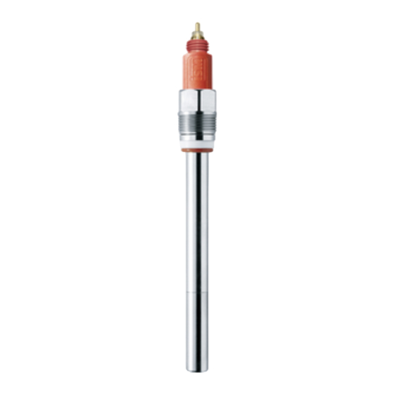
    InPro 6850 i / 6900 i / 6950 i O  Sensor 12 / 25 mm   Produktübersicht Sensor 12 mm AK9-Anschluss Gewindehülse Pg 13.5 O-Ring (9,0 1,0 mm, Silikon FDA/USP VI) Innenkörper Referenz (Ag/AgCl) Anode (Pt) Kathode und Schutzring Kontermutter Innenkörper O-Ring (Silikon FDA/USP VI) Membrankörper Überwurfhülse (Typ N) Wässerungskappe   METTLER TOLEDO O -Sensoren werden mit mon- tiertem Membrankörper, ohne Elektrolyt und mit  aufgesteckter Schutzkappe ausgeliefert und sind auf ...
  • Seite 52: Installation

    52  InPro 6850 i / 6900 i / 6950 i O  Sensor 12 / 25 mm Installation Einbau des Sensors Wichtig! Vor dem Einbau des Sensors muss die Schutzkappe entfernt werden. Einbau des Sensors in eine Armatur   Für den Einbau des Sensors in eine Armatur be- achten Sie bitte die Angaben in der entsprechenden  Anleitung zur Armatur. Direkter Einbau der Sensoren in ein Rohr / einen Kessel   Die 12 mm Sauerstoffsensoren können direkt in ei- nen Gewindestutzen Pg 13.5 eingeschraubt und mit ...
  • Seite 53: Anschluss Des Ak9-Kabels Am Transmitter

     Sensor 12 / 25 mm   AK9- oder VP-Kabel als Standard Steckerbuchse AK9-Anschlussstecker 4.2.2 Anschluss des AK9-Kabels am Transmitter -Transmitter AK9-Kabel Hinweis: Um das AK9-Kabel mit dem Transmitter zu verbinden, beachten Sie die Anweisungen in der METTLER TOLEDO Transmitter Bedienungsan- leitung. © 04 / 13 Mettler-Toledo AG    InPro 6850 i / 6900 i / 6950 i  Printed in Switzerland  52 206 349...
  • Seite 54: Betrieb

    54  InPro 6850 i / 6900 i / 6950 i O  Sensor 12 / 25 mm Betrieb Wichtig! Vor der ersten Inbetriebnahme muss der Elektrolyt eingefüllt werden (siehe «Kapitel 6.2»). Inbetriebnahme und Polarisation Wichtig! Vor dem Einbau / der Inbetriebnahme des Sensors muss die Schutzkappe entfernt werden.   Bei der ersten Inbetriebnahme oder nach einer  Trennung des Sensors von der Spannungsquelle  (Transmitter oder O  Sensor-Master) von mehr als  5 Minuten, muss der Sensor vor der Kalibrierung zur  Polarisation an den eingeschalteten O -Transmitter ...
  • Seite 55: Kalibrierung

    InPro 6850 i / 6900 i / 6950 i O  Sensor 12 / 25 mm   konzentrationen (< 500 ppb in Flüssigkeiten  oder < 10’000 ppm [Vol.] in Gasen) in Gegen- wart von sauren, flüchtigen Komponenten (z.B.  Kohlen  d ioxid bei Messung in Brauerei)   z.B. InPro 6900 i / 6950 i: – 500 mV Hinweis: Der Transmitter ist so einzustellen, dass er die korrekte Polarisationsspannung liefert. Kalibrierung 5.2.1 Zweck der Kalibrierung   Jeder Sauerstoffsensor hat eine individuelle Steil- heit und einen individuellen Nullpunkt. Beide Werte  ändern sich z.B. durch Elektrolytverbrauch oder nach  Austausch des Elektrolyten oder des Membrankör- pers. Um eine hohe Messgenauigkeit des Sensors  zu erzielen, muss deshalb regelmässig, zumindest  aber nach einem Elektrolyt- oder Membranwech- sel eine Kalibrierung durchgeführt werden. Vor der  Kalibrierung muss der Sensor mindestens 6 Stunden  polarisiert werden. Vor der Kalibrierung ist die Schutzkappe zu ent- fernen und der Sensor mit Wasser zu spülen und zu trocknen.
  • Seite 56: Einpunktkalibrierung

    56  InPro 6850 i / 6900 i / 6950 i O  Sensor 12 / 25 mm Luft im Gleichgewichtszustand befinden. Der  Sauerstoffaustausch zwischen Wasser und Luft  läuft nur sehr langsam ab. Es dauert daher relativ  lange, bis Wasser mit Luft gesättigt ist. –  Eine gewisse Mindestanströmung des Sensors  mit dem Kalibriermedium muss gewährleistet  sein. –  Achten Sie darauf, dass alle anderen Parameter,  (wie Temperatur und Druck) während der Kalib- rierung konstant bleiben.   Bei Dauerbetrieb empfehlen wir eine periodische Nachkalibrierung entsprechend der gewünschten Genauigkeit, der Art des Prozesses und Ihrer Erfahrung. Die Häufigkeit der notwendigen Nachka- librierung ist stark applikationsspezifisch und kann  daher an dieser Stelle nicht genau definiert werden. 5.2.3 Einpunktkalibrierung   Durch die Einpunktkalibrierung wird die aktuelle  Steilheit des Sensors ermittelt. Als Kalibriermedium  dient Wasser mit bekannter Sauerstoffsättigung (z.B.  luftgesättigtes Wasser) oder Luft mit bekannter Was- serdampfsättigung (wasserdampfgesättigte Luft).
  • Seite 57: Wartung

    InPro 6850 i / 6900 i / 6950 i O  Sensor 12 / 25 mm   Wartung Kontrolle des Sensors 6.1.1 Visuelle Kontrolle   Zur Überprüfung des Sensors empfehlen wir folgende  Vorgehensweise: –  Die Kontakte am Anschlussstecker müssen tro- cken sein. Feuchtigkeit, Korrosion und Schmutz  im Anschlussstecker können zu Fehl  a nzeigen  führen. –  Kabel auf Knickstellen, spröde Stellen oder Brü- che überprüfen. –  Vor jeder Kalibrierung sollte die Membranfolie op- tisch auf Beschädigung geprüft werden. Sie muss  unverletzt und sauber sein. Bei verschmutzter  Membran ist sie mit einem feuchten, weichen  Lappen abzureiben. Hinweis: Eine verformte Membrane hat keinen Einfluss auf die Messgenauigkeit, sofern Sie nicht beschädigt ist.
  • Seite 58: Kontrolle Des Sensors Mit Dem

    58  InPro 6850 i / 6900 i / 6950 i O  Sensor 12 / 25 mm 6.1.2 Kontrolle des Sensors mit dem METTLER TOLEDO Sensor-Master   Zur einfachen Überprüfung der Funktionstüchtigkeit  des Sensors empfehlen wir den als Zubehör erhältli- chen O  Sensor-Master. Um den Sensor zu kontrollie- ren, gehen Sie wie folgt vor: •  Sensor an den O  Sensor-Master anschliessen. Schalter   Sobald der Sensor am O  Sensor-Master ange- schlossen ist, wird automatisch die Polarisier- funktion aktiviert und der Sensor mit der richtigen  Polarisationsspannung versorgt. Falls der Sensor  für mehr als 5 Minuten vom Transmitter getrennt  war, muss er zuerst polarisiert (Polarisationszei- ten siehe «Kapitel 5.1») werden, bevor aussage- kräftige Testresultate erzielt werden. •  Kontrolle der Batterie:   Schalter nach links drücken. Ist der Ladezustand  der Batterie ok, leuchtet die grüne LED. Andern- falls konsultieren Sie die Bedienungsanleitung ...
  • Seite 59: Kontrolle Des Sensors Mit Dem Transmitter

    InPro 6850 i / 6900 i / 6950 i O  Sensor 12 / 25 mm   liefert, im zulässigen Bereich liegt, z.B. 2500 –  6000 nA für den InPro 6950 i.   Leuchtet die grüne LED, liegt der Elektrodenstrom  im zulässigen Bereich.   Leuchtet die LED nicht, prüfen Sie die Batterie des   Sensor-Master (siehe Bedienungsanleitung  «Zubehör»). Ist die Batterie ok, liegt der Fehler  möglicherweise beim Sensor. Ersetzen Sie den  Elektrolyten und / oder den Membrankörper des  Sensors. Leuchtet die LED auch nach dem Aus- tausch des Membrankörpers nicht, ersetzen Sie  auch noch den Innenkörper des Sensors (siehe  «Kapitel 6.2»). Wichtig! Mit der Sensor Check-Funktion wird nur die Korrektheit des Elektrodenstromes an Luft überprüft. Um sicher zu gehen, dass der Sensor korrekt arbeitet, muss auch der Nullstrom mit ei- ner Messung in sauerstofffreiem Medium überprüft werden (siehe «Kapitel 6.1.3»).
  • Seite 60: Ism-Ausführung

    60  InPro 6850 i / 6900 i / 6950 i O  Sensor 12 / 25 mm auch eine leichte Verfärbung des Elektrolyten haben  in den meisten Fällen absolut keinen Einfluss auf die  Messeigenschaften des Sensors. 6.1.4 ISM-Ausführung   Die integrierten ISM-Funktionen erlauben eine  umfangreiche Überwachung des Sensors. Folgende  Parameter werden im Sensor gespeichert: –  Serien-Nr. –  Sensor-Typ –  Bestellnummer –  Kalibrationsdaten –  CIP / SIP-Zähler –  Steigung –  Nullpunkt   Beim Start werden folgende automatische Prüfproze- duren ausgeführt: –  Digitale Kommunikation –  «Plug & Measure™» –  Vorkalibrierung –  Predictive Maintenance Ersetzen des Elektrolyten, des Membrankörpers oder des Innenkörpers Hinweis: In den Sensoren InPro 6900 i und InPro 6950 i wird ein spezieller Elektrolyt verwen-...
  • Seite 61 InPro 6850 i / 6900 i / 6950 i O  Sensor 12 / 25 mm     Für den Austausch des Elektrolyten, des Membran- körpers oder des Innenkörpers gehen Sie wie folgt  vor (siehe auch nachfolgende Abbildung): Vorsicht! Führen Sie die nachfolgenden Arbeits- schritte nur an einem sauberen Arbeitsplatz aus. 1.  Überwurfhülse vom Sensorschaft abschrauben  und vorsichtig vom Sensor ziehen. 2.  Membrankörper vom Innenkörper abziehen.  Ist der Membrankörper in der Überwurfhülse  festgeklemmt, sollte er mit der flachen Seite der  Fingerspitzen aus dieser herausgedrückt werden.  Vor einem Elektrolytwechsel muss der Membran- körper unbedingt aus der Überwurfhülse entfernt  werden! 3.  Den Innenkörper mit destilliertem Wasser abspü- len und sorgfältig mit einem Papiertuch trocknen. Hinweis: Die Schritte 4 bis 7 müssen nur für den Austausch des Innenkörpers ausgeführt werden.
  • Seite 62 62  InPro 6850 i / 6900 i / 6950 i O  Sensor 12 / 25 mm Hinweis: Darauf achten, dass im gefüllten Mem- brankörper keine Luftblasen vorhanden sind. Luftblasen können durch vorsichtiges Klopfen an den Membrankörper entfernt werden. 10.  D en Membrankörper in senkrechter Position auf  den Innenkörper schieben und überschüssigen  Elektrolyt mit einem Papiertuch entfernen. Wichtig! Zwischen Membrankörper und Überwurf- hülse dürfen sich weder Elektrolyt noch Mess- medium oder andere Verunreinigungen befinden.
  • Seite 63 InPro 6850 i / 6900 i / 6950 i O  Sensor 12 / 25 mm   Ersetzen des Innenkörpers AK9-Anschluss Gewindehülse Pg 13.5 O-Ring (9,0 1,0 mm, Silikon FDA/USP VI) Innenkörper Referenz (Ag/AgCl) Anode (Pt) Kathode und Schutzring Kontermutter Innenkörper Membrankörper O-Ring (Silikon FDA/USP VI) Überwurfhülse (Typ N) Schutzkappe © 04 / 13 Mettler-Toledo AG    InPro 6850 i / 6900 i / 6950 i  Printed in Switzerland  52 206 349...
  • Seite 64: Lagerung

    64  InPro 6850 i / 6900 i / 6950 i O  Sensor 12 / 25 mm Lagerung   Für die Lagerung der Sensoren über eine Dauer von  mehr als 24 Stunden empfehlen wir, die Schutzkap- pe, gefüllt mit der Reinigungs- und Konditionierlö- sung (Bestell-Nr. 52 200 255), wie sie für unsere  portablen O -Messsysteme verwendet wird, aufzuset- zen. Diese Lösung besitzt einen Oxydationshemmer,  der verhindert, dass der Sensor mit Sauerstoff in  Kontakt kommt, wenn er nicht benutzt wird.   Wenn der Sensor ohne Polarisierung über eine  Woche gelagert wird, muss der Elektrolyt entfernt  werden.   Um die Reinigungs- und Konditionierlösung her- zustellen, gehen Sie wie folgt vor: Eine Tablette in  40 ml destilliertes Wasser geben und 5 Minuten  warten, bis sie sich aufgelöst hat. Schutzkappe  mit dieser Lösung füllen und Schutzkappe auf  das Sensor  e nde aufstecken. Die Reinigungs- und  Konditionier  l ösung hat Reinigungseigenschaften, die  die Membran freihält von Mikroorganismen. Falls Sie  kein Reinigungs- und Konditionierset haben, können  Sie die Schutzkappe auch mit Prüfgel oder entgastem  Wasser füllen. Vor dem Einbau des Sensors ist die  Schutzkappe zu entfernen und der Sensor mit Wasser  zu spülen. Vorsicht! Bei einer Lagerung des Sensors ohne Spannungsversorgung (Transmitter, Sensor- Master) von mehr als 1 Woche sollte der Sensor trocken, d.h.
  • Seite 65: Technische Daten

    InPro 6850 i / 6900 i / 6950 i O  Sensor 12 / 25 mm   Technische Daten InPro 6850 i / 6900 i / 6950 i           Messprinzip      Polarografische Clark-Elektrode Betriebsbedingungen   Zulässiger Druckbereich    6850 i:   0,2 … 6 bar     (Messung)      6900 i:   0,2 … 6 bar               (9 bar mit T-6900R) ...
  • Seite 66: Bestellinformationen

    66  InPro 6850 i / 6900 i / 6950 i O  Sensor 12 / 25 mm Zertifikate   EHEDG, 3A        3.1 B (EN 10204.3 /1.B)    ATEX-Zertifikat      6850 i / 6900 i:  Ja            6950 i    Nein   FM-Zulassung      6850 i / 6900 i:  Ja            6950 i    Nein   FDA / USP VI   ...
  • Seite 67: Ersatzteile

    InPro 6850 i / 6900 i / 6950 i O  Sensor 12 / 25 mm   Ersatzteile Ersatzteil Bestell-Nr. – InPro 6850 i Membrankörper (einzeln), T-96      52 200 071 Membran-Kit T-96 (4 Membrankörper,     52 200 024  1 O-Ring-Set (Silikon), 25 ml Elektrolyt,   medienberührte Teile SS 316L) Membrankörper (16 Stück), T-96      52 206 114 Elektrolyt-Nachfülllösung (25 ml)      34 100 2016 Innenkörper (Ersatz), InPro 6850 i      52 206 347 – InPro 6900 i Verstärkter Membrankörper (single),      52 201 108    I nPro 6900 (T-6900R) Verstärktes Membran-Kit ...
  • Seite 68: Empfohlene Armaturen

      Eintaucharmatur InDip 550 Hinweis: Die Armaturen sind in verschiedenen Versionen erhältlich. Um sicherzustellen, dass die Bestellnummer mit der gewünschten Version übereinstimmt, nehmen Sie bitte mit Ihrer METTLER TOLEDO Verkaufsorganisation Kontakt auf. Theorie der polarographischen Sensoren 10.1 Einführung   In der analytischen Messung werden zwei verschie- dene Typen von Elektroden verwendet: Die potentio- metrischen und die amperometrischen.
  • Seite 69: Prinzipieller Aufbau Von Sauerstoffelektroden

    InPro 6850 i / 6900 i / 6950 i O  Sensor 12 / 25 mm   die Potentialdifferenz zwischen der Messelektrode  und einer fixen Referenzelektrode. Der Span- nungswert der Referenzelektrode muss dabei  konstant sein.   Alle potentiometrischen Elektroden unterliegen  den Gesetzen nach Nernst. Aus diesem Grund  können  die Elektroden und die Messinstrumente  in den meisten Fällen untereinander ausgetauscht  werden. Eine wichtige Eigenschaft der potentio- metrischen Messungen ist die praktisch stromlo- se Bestimmung der Elektrodenspannung.   Dadurch entstehen im Messmedium keine che- mischen Reaktionen und das Messmedium bleibt  im Gleichgewicht. –  Bei den amperometrischen Elektroden, wie zum  Beispiel den Sauerstoffelektroden, basiert die  Messung auf einer Strommessung.  Die herkömmlichen Sauerstoffelektoden bestehen aus einer Kathode und einer Anode, die über einen Elektrolyten miteinander leitend verbunden sind. Eine geeignete Polarisations- spannung zwischen Anode und Kathode reduziert  den Sauerstoff an der Kathode.
  • Seite 70 70  InPro 6850 i / 6900 i / 6950 i O  Sensor 12 / 25 mm –  Keine oder sehr geringe Abhängigkeit von den  Strömungsbedingungen im Medium   Bei den Clark-Elektroden ist die konstruktive Aus- legung sehr wichtig. Speziell die Dicke des Elektro- lytfilms zwischen der Kathode und der Membrane  muss in sehr engen Grenzen gehalten werden, um  eine gute Linearität und einen tiefen Nullstrom (Strom  in reinem Stickstoff) zu gewährleisten.    Die Sauerstoffsensoren von METTLER TOLEDO wer- den in verschiedenen Bauweisen angeboten: Typ A, 2 Elektroden System, InPro 6800   InPro 6800 für mittlere und höhere Sauerstoffkonzen- trationen. Kathode und Anode Referenz. Anode und      Referenz sind in einer Silber Silberchloridelektrode      vereinigt.    An der Anode bzw. Referenz findet folgende Gleich- gewichtsreaktion statt: –   Reaktion:  4 Ag + 4 Cl   ...
  • Seite 71 InPro 6850 i / 6900 i / 6950 i O  Sensor 12 / 25 mm   Polarisations- spannung Referenz Kathode Anode Elektrolyt Glasisolator NTC 22 k Membrane Messung in Flüs- sigkeit oder Gas   Typ C, 3 Elektroden, InPro 6900     InPro 6900 und InPro 6900 i. Für Sauerstoffmes-   sungen im unteren ppb-Bereich. Anode und Refe- renz sind hier in einer Silber Silberchloridelektrode      vereinigt (wie bei Typ A). Die Sensoren verfügen  über einen zusätzlichen Guard-Ring um die Kathode.  Dieser bildet wie die Kathode mit der Anode einen  geschlossenen Stromkreis, welcher verhindert, dass  Sauerstoff von der Seite zu der Kathode diffundiert ...
  • Seite 72 72  InPro 6850 i / 6900 i / 6950 i O  Sensor 12 / 25 mm Typ D, 4 Elektroden, InPro 6950     Der InPro 6950 (i) ist vorgesehen zur Messung von    permanent niedrigem Sauerstoff bis zu 0.1ppb. In  Hinsicht auf das Messprinzip ist er eine Kombina- tion aus dem InPro6850 i und 6900 (i). Er besitzt      4 Elektroden. Anode und Referenz sind separiert in  2 Elektroden. Eine Platin Anode und eine Silber Sil-     berchlorid Referenz. Eine Schuzringelektrode um die  Kathode, wie beim InPro6900 i ist ebenfalls vorhan-   den. Die Kathode besitzt den grössten Durchmesser  von allen amperometrischen Sensoren von METTLER   TOLEDO   An der Elektrode finden folgende Reaktionen statt: –   Kathode:   + 2 H O + 4 e –...
  • Seite 73: Einflussgrössen Auf Den Elektrodenstrom

    InPro 6850 i / 6900 i / 6950 i O  Sensor 12 / 25 mm   10.3 Einflussgrössen auf den Elektrodenstrom   Die Menge des diffundierten Sauerstoffs und die  Grösse des Elektrodenstromes werden von folgenden  Einflussgrössen bestimmt: –  Sauerstoffpartialdruck im Messmedium –  Membranmaterial und -dicke –  Grösse der Kathode –  Polarisationsspannung –  Temperatur –  Strömungsbedingungen im Messmedium   Das Gesetz nach Fick zeigt den mathematischen  Zusammenhang dieser Einflussgrössen auf:     I   =  Electrodenstrom   k   =  Konstante   D   =  O -Durchdringungskoeffizient der Membran  ...
  • Seite 74: Temperatur

    74  InPro 6850 i / 6900 i / 6950 i O  Sensor 12 / 25 mm   Die Anode muss eine grosse Oberfläche aufweisen,  damit sie nicht vom Elektrodenstrom polarisiert wird. 10.5 Temperatur   Die Temperaturabhängigkeit des Elektrodenstroms  bezogen auf einen konstanten Sauerstoffpartialdruck  ist überwiegend durch die Eigenschaften der gas- durchlässigen Membran bestimmt. 10.6 Strömungsabhängigkeit   Bei den meisten Sauerstoffelektroden ist der Elek- trodenstrom in ruhigen Messmedien kleiner als in  bewegten Medien. Durch den Sauerstoffverbrauch der  Elektrode wird ausserhalb der Membran in unmittel- barer Nähe der Kathode Sauerstoff aus dem Mess- medium zu H O reduziert. Der fehlende Sauerstoff  wird durch Diffusion innerhalb des Messmediums  wieder ersetzt. Ist der Elektrodenstrom sehr hoch,  kann der reduzierte Sauerstoff durch die Diffusion  nicht mehr vollständig ersetzt werden. Dadurch  resultiert ein Elektrodenstrom der tiefer ist als der, der  tatsächlich dem Messmedium entsprechen wür- de. In bewegten Messmedien wird der verbrauchte  Sauerstoff nicht nur durch Diffusion innerhalb der  Flüssigkeit zugeführt, sondern zusätzlich durch die  vorbeiströmende Flüssigkeit (Konvektion). Dadurch  wird eine Abnahme des Sauerstoffgehaltes an der  Membranoberfläche verhindert.   Stark abhängig von den Strömungsbedingungen sind  Elektroden mit grossen Kathoden und dünnen hoch- durchlässigen Membranen (Elektroden mit hohem  Elektrodenstrom).  ...
  • Seite 75: Sauerstoffpartialdruck - Sauerstoffkonzentration

    InPro 6850 i / 6900 i / 6950 i O  Sensor 12 / 25 mm   10.7 Sauerstoffpartialdruck – Sauerstoffkonzentration   Der Elektrodenstrom ist abhängig vom Sauerstoff- partialdruck und der Sauerstoffdurchlässigkeit der  Membran. Die Umrechnung von Partialdruck in  Sauerstoffkonzentration hängt vom Messmedium  (Messung in Flüssigkeiten oder Gasen) ab. Messung in Flüssigkeiten   Wird in Flüssigkeiten gemessen, hängt die Sauer- stoffkonzentration zusätzlich von der Löslichkeit des  Sauerstoffs im Messmedium ab. Da diese aber vom  Sensorstrom nicht erfasst wird, muss die Sauerstoff- konzentration im Transmitter berechnet werden. Dazu  wird das Gesetz nach Henry angewendet welches  besagt, dass die Sauerstoffkonzentration proportional  zum Sauerstoffpartialdruck (pO ) ist.   a  =  Löslichkeitsfaktor    Wenn «a» konstant ist, kann die Sauerstoffkonzen- tration mit der Elektrode bestimmt werden. Dies  stimmt jedoch nur bei konstanter Temperatur und für  verdünnte wässerige Lösungen, wie zum Beispiel  Trinkwasser.   Der Löslichkeitsfaktor ist nicht nur im starken Masse  von der Temperatur abhängig, sondern auch von der  Zusammensetzung des Messmediums: Medium, Löslichkeit bei 20 °C gesättigt mit Luft und 760 mm Hg  ...
  • Seite 76 76  InPro 6850 i / 6900 i / 6950 i O  Sensor 12 / 25 mm   Beispiel:   Allgemein bekannt sind die Volumenprozent Angaben  bei der Zusammensetzung der Luft. So enthält Luft  beispielsweise 20,95 % Sauerstoff. Dies entspricht    209’500 ppm (Vol.).   (Umrechnung: Wert ppm = 10’000 3 Wert in %) Referenzen –  W.M. Krebs, I.A. Haddad Develp. Ind. Microbio.,  13, 113 (1972) –  H. Bühler, W. Ingold GIT 20, 977 (1976) –  W.M. Krebs, MBAA Techn. Quart. 16, 176  (1975) –  D.P. Lucero, Ana. Chem. 40, 707 (1968) InPro 6850 i / 6900 i / 6950 i  © 04 / 13 Mettler-Toledo AG 52 206 349  Printed in Switzerland...
  • Seite 77 InPro 6850 i / 6900 i / 6950 i O  Sensor 12 / 25 mm   Notizen © 04 / 13 Mettler-Toledo AG    InPro 6850 i / 6900 i / 6950 i  Printed in Switzerland  52 206 349...
  • Seite 78 78  InPro 6850 i / 6900 i / 6950 i O  Sensor 12 / 25 mm Sondes O InPro 6850 i, 6900 i & 6950 i ® Instructions d’utilisation InPro 6850 i / 6900 i / 6950 i  © 04 / 13 Mettler-Toledo AG 52 206 349  Printed in Switzerland...
  • Seite 79 InPro 6850 i / 6900 i / 6950 i O  Sensor 12 / 25 mm   Table des matières Introduction Remarques importantes 2.1  Remarques concernant les instructions d’utilisation  2.2  Emploi approprié  2.3  Consignes de sécurité  2.4  Quelques exemples typiques d’application    2.5  Utilisation dans les zones Ex (pas pour l´InPro 6950 i)  83   2.6  Classification Ex selon ATEX (pas pour l´InPro 6950 i)  84 2.6.1   Introduction  2.6.2   Caractéristiques nominales  2.6.3  Conditions particulières    2.7  Classification Ex – FM Approved  Description du produit 3.1  Informations générales ...
  • Seite 80: Introduction

    80  InPro 6850 i / 6900 i / 6950 i O  Sensor 12 / 25 mm Introduction Nous vous remercions d’avoir acheté la sonde O   InPro 6850 i / 6900 i / 6950 i de METTLER TOLEDO.   Les sondes de la série InPro sont construites selon  l’état actuel de la technique et correspondent aux  règles techniques de sécurité reconnues. Cela n’em- pêche, qu’en cas de fausse manipulation, elles puis- sent présenter des dangers pour l’opérateur ou pour  des tiers, ou encore pour l’installation elle-même ou  d’autre biens corporels.  C’est pourquoi les personnes concernées doivent d’abord lire et comprendre les Instructions d’utili- sation.
  • Seite 81: Remarques Importantes

    éventuelle diminution de la production. Emploi approprié Les capteurs METTLER TOLEDO InPro 6850 i / 6900 i / 6950 i servent à la mesure en ligne de la pression partielle d’oxygène dans les liquides et les gaz, conformément aux indications de cette notice d’emploi.
  • Seite 82: Consignes De Sécurité

    82  InPro 6850 i / 6900 i / 6950 i O  Sensor 12 / 25 mm –  L’utilisation correcte en respectant les conditions  d’exploitation et de protection de l’environnement  prescrites ainsi que les installations accessoires  autorisées. –  En cas d’incertitude, s’informer impérativement  auprès de METTLER TOLEDO. Consignes de sécurité –  L’exploitant de l’installation doit être conscient     des éventuels risques et dangers de son procédé     ou installation. Il est responsable de la forma-    tion du personnel servant, de la signalisation des     dangers potentiels et du choix de l’instrumenta-    tion appropriée en fonction de l’état de la     technique. –  Le personnel servant impliqué dans la mise en  service, l’utilisation et l’entretien de ce capteur  ou d’un de ses produits auxiliaires (supports,  transmetteurs, etc.) doit nécessairement être  instruit du procédé de production et des produits.  Ceci inclut la lecture et la compréhension de la  présente notice d’emploi. –  La sécurité du personnel servant et des installa- tions incombe en dernier ressort à l’exploitant de  l’installation. Ceci s’applique notamment aux ins- tallations se trouvant dans des zones à danger ...
  • Seite 83: Quelques Exemples Typiques D'application

    InPro 6850 i / 6900 i / 6950 i O  Sensor 12 / 25 mm   –  Ne pas apporter de modifications aux capteurs et  aux accessoires. Le fabricant/fournisseur décline  toute responsabilité en cas de modifications  non autorisées, dont seul l’utilisateur assume le  risque. Quelques exemples typiques d’application   La liste suivante énumère quelques exemples d’ap- plication typiques, non limitatifs, du capteur d’oxy- gène. Mesure dans des liquides : –  Biotechnologie –  Applications chimiques –  Brasseries –  Filtration de boissons –  Conditionnement de boissons Mesure dans des gaz : –  Récupération de CO –  Pureté du CO – ...
  • Seite 84: Classification Ex Selon Atex (Pas Pour L´inpro 6950 I)

    84  InPro 6850 i / 6900 i / 6950 i O  Sensor 12 / 25 mm Classification Ex selon ATEX (pas pour l´InPro 6950   2.6.1 Introduction   Conformément à l’annexe I de RL 94/9/EC (ATEX 95)  des dispositifs du groupe de matériels II Categorie  1/2G conformément à RL 99/92/EC (ATEX 137), les  sondes O  InPro 6XXX*/*/*/*/* peuvent être utilisées  dans les zones 0/1 ou 0/2, ainsi que les groupes  de gaz IIA, IIB et IIC, soumis au danger d’explosion  par des matériaux combustibles dans la plage des  classes de température T3 à T6.   Dans le cadre du montage et de l’utilisation, les  exigences doivent être conformes à la norme EN  60079-14.   Conformément à l’annexe I de RL 94/9/EC (ATEX 95)  des dispositifs du groupe de matériels II Categorie  1/2D conformément à RL 99/92/EC (ATEX 137), les  sondes O  InPro 6XXX*/*/*/*/* peuvent aussi être  utilisées dans les zones 20/21, soumis au danger  par des poussières combustibles.   Dans le cadre du montage et de l’utilisation, les  exigences doivent être conformes à la norme EN  61241-14.  ...
  • Seite 85: Conditions Particulières

    InPro 6850 i / 6900 i / 6950 i O  Sensor 12 / 25 mm   2.6.3 Conditions particulières –  Les températures ambiantes resp. médias  permises maximum pour la zone 0 (les gaz  combustibles ou les liquides combustibles) sont  conformes aux classes de la température mon- trées dans la table ci-dessous : Classe de Température ambiante     température resp. média max.     T 6       68 °C     T 5       80 °C     T 4       108 °C    ...
  • Seite 86: Classification Ex - Fm Approved

    86  InPro 6850 i / 6900 i / 6950 i O  Sensor 12 / 25 mm Classification Ex – FM Approved   InPro 6850 i / 6900 i / 6950 i  © 04 / 13 Mettler-Toledo AG 52 206 349  Printed in Switzerland...
  • Seite 87: Description Du Produit

    InPro 6850 i / 6900 i / 6950 i O  Sensor 12 / 25 mm   Description du produit Informations générales   Les sondes de la série InPro 6850 i / 6900 i / 6950 i  avec sonde de température intégrée sont utilisées  pour la mesure précise de faibles et moyennes  concentrations d’oxygène.   Les sondes sont stérilisables et la plupart sont  autoclavables. Les sondes sont compatible NEP  (Nettoyage-En-Place).   Les sondes InPro 6xxx i avec fonctionnalité ISM per- mettent le « Plug & Measure » et offrent des fonction- nalités de diagnostic étendues. Principe de fonctionnement Sondes d’oxygène polarographiques :   Le système de mesure de toutes les sondes d’oxy- gène polarographiques repose sur la configuration  de Clark. Il existe toutefois différents modèles dont  les spécifications varient nettement en fonction du  nombre et de l’implantation des électrodes : • ...
  • Seite 88: Livraison

    88  InPro 6850 i / 6900 i / 6950 i O  Sensor 12 / 25 mm   Le système à 4 électrodes de la sonde InPro 6950  garantit une grande justesse, une réponse rapide et  une limite de détection basse. Indication : pour de plus amples informations, reportez-vous au « Chapitre 10 – Théorie de la sonde polarographique ». Sondes ISM :   Toutes les sondes à oxygène avec suffixe « i »  (6850 i, 6900 i, 6950 i) sont équipées de l’ISM.   Principe : la tête de la sonde est équipée d’une puce.  Celle-ci sert non seulement à commander et contrô- ler la sonde, mais aussi à enregistrer l’ensemble des  données. Cette puce communique avec le transmet- teur.   Les données de la sonde disponibles en permanence  sont les suivantes : –  ...
  • Seite 89: Pièces De L'appareil

    InPro 6850 i / 6900 i / 6950 i O  Sensor 12 / 25 mm     Dans le cas des sondes numériques, il est néces- saire de faire un appoint d’électrolyte avant la mise  en service. Pièces de l’appareil Sonde 12 mm Connecteur AK9 Douille filetée Pg 13.5 Joint torique (9,0 1,0 mm, silicone FDA/USP VI) Corps interne Référence (Ag/AgCl) Anode (Pt) Cathode et anneau de garde (« Guard ring ») Ecrou de maintien Joint torique (silicone FDA/USP VI) Module à...
  • Seite 90: Installation

    90  InPro 6850 i / 6900 i / 6950 i O  Sensor 12 / 25 mm Installation Montage de la sonde Important ! Avant de monter la sonde, enlevez le capuchon de protection. Montage de la sonde dans un support   Veuillez vous reporter au manuel du support afin de  savoir comment monter la sonde à cet endroit. Montage de la sonde, directement sur un tuyau ou une cuve  ...
  • Seite 91: Connexion Du Câble Ak9 Au Transmetteur

    Fiche Connecteur AK9 4.2.2 Connexion du câble AK9 au transmetteur Transmetteur O Câble AK9 Indication : pour relier le câble AK9 au transmet- teur veuillez suivre les instructions de la notice d’emploi du transmetteur METTLER TOLEDO. © 04 / 13 Mettler-Toledo AG    InPro 6850 i / 6900 i / 6950 i  Printed in Switzerland  52 206 349...
  • Seite 92: Fonctionnement

    92  InPro 6850 i / 6900 i / 6950 i O  Sensor 12 / 25 mm Fonctionnement Important ! Il faut verser l’électrolyte avant la première mise en service (voir « Chapitre 6.2 »). Mise en service et polarisation   Important ! Avant le montage / la mise en service de  la sonde, enlevez le capuchon de protection.   Lors de la première mise en service de la sonde,  ou si la sonde a été déconnectée de sa source de  tension (transmetteur ou module de polarisation)  pendant plus de 5 minutes, la sonde doit être pola- risée, avant étalonnage, en la reliant au transmetteur   en marche ou à un module de polarisation. La  sonde est polarisée et prête à fonctionner au bout de  six heures.  L’InPro 6950 i ne doit jamais être polarisé à l’air!  ...
  • Seite 93: Etalonnage

    InPro 6850 i / 6900 i / 6950 i O  Sensor 12 / 25 mm   composants acides volatils (par exemple dioxyde  de carbone pour les mesures en brasserie) p. ex.  InPro 6900 i / 6950 i : – 500 mV Indication : Le transmetteur doit être réglé de fa- çon à délivrer la tension de polarisation correcte. Etalonnage 5.2.1 L’effet de l’étalonnage   Chaque sonde d’oxygène a une pente et un zéro  caractéristiques. Les deux valeurs changent, par  exemple, par épuisement de l’électrolyte ou après  remplacement de l’électrolyte ou du module à  membrane. Afin que la sonde mesure avec une  haute exactitude, il faut par conséquent effectuer un  étalonnage régulièrement, au moins toutefois après  remplacement de l’électrolyte ou de la membrane.  Avant l’étalonnage, il faut polariser la sonde pendant  au moins 6 heures. Avant l’étalonnage, ôtez le capuchon de protection et rincez la sonde à...
  • Seite 94: Etalonnage À Un Point

    94  InPro 6850 i / 6900 i / 6950 i O  Sensor 12 / 25 mm –  Si l’étalonnage a lieu dans l’eau ou dans un  milieu de mesure, le milieu d’étalonnage doit être en état d’équilibre avec l’air. L’échange  d’oxygène entre l’eau et l’air est très lent. Il faut  par conséquent relativement longtemps pour  saturer l’eau en air. –  Un minimum de circulation est nécessaire dans  le milieu qui baigne la sonde. –  Veiller à maintenir constants tous les autres para- mètres comme la température et la pression.   En fonctionnement continu nous recommandons un  reétalonnage périodique dépendant de l’exactitude souhaitée, de la nature du procédé et de votre expérience. La fréquence de reétalonnage requise ...
  • Seite 95: Entretien

    InPro 6850 i / 6900 i / 6950 i O  Sensor 12 / 25 mm   Entretien Contrôle de la sonde 6.1.1 Examen visuel   Pour contrôler la sonde, nous recommandons de  procéder comme suit : –  Les contacts du connecteur doivent être secs. La  présence d’humidité, de traces de corrosion et de  saletés sur les contacts peut causer de fausses  valeurs de mesure. –  Vérifier que le câble ne présente pas de pliures,  de points fragiles ou de ruptures. –  Avant chaque étalonnage vérifier visuellement le  bon état de la membrane. Elle doit être intacte  et propre. Si elle est sale, nettoyer la membrane  avec un chiffon doux et humide. Indication: pour autant qu’elle soit intacte, une membrane qui ondule n’a aucun impact sur les performances de la sonde.
  • Seite 96: Test De La Sonde Avec Le O 2 Sensor-Master De

    96  InPro 6850 i / 6900 i / 6950 i O  Sensor 12 / 25 mm 6.1.2 Test de la sonde avec le O Sensor-Master de METTLER TOLEDO   Nous vous recommandons d’utiliser le O  Sensor- Master de METTLER TOLEDO afin de vérifier la qualité  de votre sonde. Pour ce faire, procédez comme suit : •  Connectez la sonde au O  Sensor-Master. Voyant lumineux Interrupteur   La fonction de polarisation est activée dès la  connexion de la sonde au O  Sensor-Master. Si la  sonde a été débranchée du transmetteur pendant  plus de 5 minutes, polarisez la sonde (temps de  polarisation, voir « Chapitre 5.1 ») afin d’obtenir  des résultats de test représentatifs. •  Vérification de la pile : ...
  • Seite 97: Test De La Sonde À L'aide D'un Transmetteur

    InPro 6850 i / 6900 i / 6950 i O  Sensor 12 / 25 mm     Si le voyant lumineux ne s’allume pas, vous de- vez vérifier la pile du O  Sensor-Master (voir ins- tructions d’utilisation « Accessoires »). Si la pile  fonctionne, cela signifie qu’il y a probablement  un problème au niveau de votre sonde. Vous  devez, dans ce cas, changer l’électrolyte et / ou la  cartouche à membrane de la sonde. Si, une fois  la membrane remplacée, le voyant ne s’allume  toujours pas, cela signifie qu’il y a peut-être un  problème au niveau du corps interne. Vous devez  alors le remplacer (voir « Chapitre 6.2 »). Important ! Cette fonction ne vérifie que le courant dans l’air de la sonde. Pour avoir une garan- tie totale du bon fonctionnement de la sonde, un contrôle du courant résiduel dans un milieu sans oxygène doit être effectué...
  • Seite 98: Version Ism

    98  InPro 6850 i / 6900 i / 6950 i O  Sensor 12 / 25 mm 6.1.4 Version ISM   Les fonctions ISM intégrées offrent des possibilités  étendues de surveillance des sondes. Les paramètres  enregistrés dans les sondes sont les suivants : –  N° de série –  Type de sonde –  N° de commande –  Données d’étalonnage –  Compteur NEP / SEP –  Pente –  Point de zéro   Les procédures de contrôle automatique au démar- rage sont les suivantes : –  Communication numérique –  « Plug & Measure™ » –  Pré-étalonnage –  Maintenance prédictive Remplacer l’électrolyte ou le module à membrane ou le corps interne Indication : L’InPro 6900 i et 6950 i utilisent un électrolyte spécial contenant un anti-oxydant.
  • Seite 99 InPro 6850 i / 6900 i / 6950 i O  Sensor 12 / 25 mm   1.  Dévisser la gaine de la tige de sonde et la retirer  avec précaution. 2.  Retirer le module à membrane du corps interne.  Si le module à membrane est coincée dans la  gaine, l’en extraire en pressant avec la pulpe  du doigt. Avant de remplacer l’électrolyte il faut  impérativement extraire le module à membrane  de la gaine !  3.  Rincer le corps interne à l’eau déminéralisée et  le sécher soigneusement avec un mouchoir en  papier. Indication : Il faut uniquement excécuter les étapes 4 à 7 pour remplacer le corps interne. 4.  Dévissez l’écrou de maintien du corps interne au  moyen d’une clé réglable ou d’une clé 9 mm. 5.  Enlevez le corps interne en l’ôtant de l’axe de la  sonde. Si nécessaire, utilisez une pince. Attention ! Ne faites pas tourner le corps interne en l’extrayant.
  • Seite 100 100  InPro 6850 i / 6900 i / 6950 i O  Sensor 12 / 25 mm 10.  E ngager le module à membrane en position  verticale sur le corps interne. Enlever l’excédent  d’électrolyte à l’aide d’un mouchoir en papier. Important ! Entre le module à membrane et la gaine il ne doit pas y avoir d’électrolyte ni de milieu de mesure ou des saletés. Vérifier la pro- preté ! 11.  G lisser la gaine avec précaution sur le module  à membrane, maintenir la sonde en position ...
  • Seite 101 InPro 6850 i / 6900 i / 6950 i O  Sensor 12 / 25 mm   Remplacer le corps interne Connecteur AK9 Douille filetée Pg 13.5 Joint torique (9,0 1,0 mm, silicone FDA/USP VI) Corps interne Référence (Ag/AgCl) Anode (Pt) Cathode et anneau de garde (« Guard ring ») Ecrou de maintien Module à membrane Joint torique (silicone FDA/USP VI) Gaine (type N)
  • Seite 102: Conservation

    102  InPro 6850 i / 6900 i / 6950 i O  Sensor 12 / 25 mm Conservation   Pour entreposer les sondes durant plus de  24 heures, nous recommandons d’utiliser le ca- puchon de protection rempli de solution de net- toyage et de conditionnement (N° de commande  52 200 255), comme pour nos systèmes portables  de mesure de O . Cette solution contient un anti-oxy- dant qui empêche que la sonde soit en contact avec  l’oxygène lorsqu’il ne sert pas.   Lorsque la sonde est stockée sans polarisation pen- dant plus d’une semaine, l’électrolyte doit être retiré.   Pour fabriquer la solution de nettoyage et de condi- tionnement, procédez comme suit : déposez une  tablette dans 40 ml d’eau distillée et patientez 5 mi- nutes jusqu’à ce qu’elle soit dissoute. Remplissez le  capuchon de protection de cette solution et placez-le  sur l’extrémité de la sonde. La solution de nettoyage  et de conditionnement possède des propriétés  nettoyantes qui protègent la membrane des microor- ganismes. Si vous n’avez plus de set de nettoyage et  conditionnement, vous pouvez remplir le capuchon  de protection de gel d’essai ou d’eau désaérée. Avant  de monter la sonde, ôtez le capuchon de protection  et rincez la sonde dans un courant d’eau. Prudence ! En cas de stockage de la sonde sans alimentation en courant (transmetteur, Sensor- Master) de plus de une semaine, la sonde devrait être conservée à...
  • Seite 103: Caractéristiques Du Produit

    InPro 6850 i / 6900 i / 6950 i O  Sensor 12 / 25 mm   Caractéristiques du produit Certificats   Chaque sonde est livré avec un jeu de certificats 3.1 (en conformité avec la norme EN 10204).   Toutes les pièces métalliques en contact avec le mi- lieu (axe de la sonde, gaine et module à membrane)  sont identifiées à l’aide d’un symbole correspondant  au numéro de coulée. Le symbole gravé sur la  sonde correspond au numéro de coulée qui figure  sur le certificat papier délivré avec la sonde.   Chaque pièce métallique en contact avec le milieu  (axe de la sonde, gaine et module à membrane) est  polie de manière à obtenir une rugosité de surface  inférieure à 0,4 µm. Cela équivaut à un niveau de  rugosité de N5 (selon la norme ISO 1320 : 1992). © 04 / 13 Mettler-Toledo AG    InPro 6850 i / 6900 i / 6950 i  Printed in Switzerland  52 206 349...
  • Seite 104: Spécifications

    104  InPro 6850 i / 6900 i / 6950 i O  Sensor 12 / 25 mm Spécifications InPro 6850 i / 6900 i / 6950 i           Principe de mesure    Électrode Clark, polarographique Conditions d’utilisation   Domaine de pression admissible  6850 i:  0,2 … 6 bar    (mesure)      6900 i:  0,2 … 6 bar              ...
  • Seite 105: Informations Pour La Commande

    InPro 6850 i / 6900 i / 6950 i O  Sensor 12 / 25 mm   Certification   EHEDG, 3A        3.1 B (EN 10204.3 /1.B)    Certificate ATEX      6850 i / 6900 i:  Oui            6950 i:      FM Approval      6850 i / 6900 i:  Oui            6950 i:      FDA / USP VI    Contrôle qualité Oui Compatibilité  ...
  • Seite 106: Pièces De Rechange

    106  InPro 6850 i / 6900 i / 6950 i O  Sensor 12 / 25 mm Pièces de rechange Pièces détachées N° de commande – InPro 6850 i Module à membrane (seul), T-96      52 200 071 Kit modules à membrane T-96 (4 membr.,     52 200 024  1 kit de joints toriques, 25 ml d’électrolyte,   matériaux en contact avec le milieu en acier   SS 316L) Module à membrane (16 pcs), T-96    52 206 114 Electrolyte (25 ml)        34 100 2016 Elément sensible (interchang.), InPro 6850 i   52 206 347 – InPro 6900 i Module à membrane (seul), renforcée, ...
  • Seite 107: Supports Recommandés

    Support à immersion InDip 550 Indication : Les supports étant disponible dans différentes finitions, veuillez prendre contact avec votre organisation de vente METTLER TOLEDO pour vous assurez que les numéros de commande correspondent bien avec la finition désirée. Théorie de la sonde polarographique 10.1 Introduction...
  • Seite 108: Principe De Conception D'une Sonde À Oxygène

    108  InPro 6850 i / 6900 i / 6950 i O  Sensor 12 / 25 mm rence de potentiel entre l’électrode de mesure et  une électrode de référence inerte. Le potentiel de  la sonde de référence doit être constant.  Toutes les électrodes potentiométriques sont  soumises à la loi de Nernst. C’est pour cette  raison que, dans la plupart des cas, les élec- trodes et instruments de mesure ne sont pas  interchangeables. La détermination de la tension  d’électrode sans courant constitue l’une des exi- gences en matière de mesures potentiométriques.  Pendant la mesure, aucune réaction chimique ne  se produit et la solution reste en équilibre. –  Dans le cas d’électrodes ampérométriques,  telles que les sondes à oxygène, la mesure de  l’activité est basée sur la mesure du courant.   La sonde à oxygène traditionnelle se compose d’une cathode et d’une anode connectées de manière conductive par un électrolyte. Une  tension de polarisation adaptée entre l’anode et ...
  • Seite 109 InPro 6850 i / 6900 i / 6950 i O  Sensor 12 / 25 mm   –  Peu ou pas de dépendance relative à l’écoule- ment   Dans le cas de l’électrode de Clark, la configuration  géométrique est très importante. L’épaisseur du film  d’électrolyte situé entre la cathode et la membrane  doit satisfaire des tolérances très strictes, de manière  à garantir une bonne linéarité et un courant de zéro  faible (courant dans une atmosphère d’azote).   Les sondes à oxygène METTLER TOLEDO se décli- nent en différents modèles : Type A, sonde à 2 électrodes, InPro 6800   InPro 6800 pour concentrations en oxygène  moyennes et élevées. Cathode et anode / référence.  Anode et référence réunies dans une électrode ar- gent / chlorure d’argent.    La réaction d’équilibre au niveau de l’anode/réfé- rence est la suivante : –   Réaction :  4 Ag + 4 Cl      4 AgCl + 4 e – Tension de polarisation Référence / Anode Cathode Électrolyte...
  • Seite 110 110  InPro 6850 i / 6900 i / 6950 i O  Sensor 12 / 25 mm Tension de polarisation Référence Cathode Anode Électrolyte Isolant NTC 22 k Membrane Mesure dans liquides ou gaz Type C, sonde à 3 électrodes, InPro 6900 (i)   InPro 6900 et InPro 6900 i. Pour mesures de l’oxy- gène de l’ordre du ppb. Anode et référence réunies  dans une électrode argent / chlorure d’argent (comme  avec le type A). Sondes munies d’un anneau de  garde supplémentaire autour de la cathode. Cet  anneau forme, tout comme la cathode avec l’anode,  un circuit électrique fermé qui évite que l’oxygène ne  se diffuse vers la cathode sur le côté, au risque de  fausser les résultats. Tension de polarisation Référence / Anode Cathode...
  • Seite 111 InPro 6850 i / 6900 i / 6950 i O  Sensor 12 / 25 mm   Type D, sonde à 4 électrodes, InPro 6950 (i)   L’InPro 6950 i est detinée à la mesure de taux  d’oxygène dissous constamment bas, jusqu’au  niveau de 0,1 ppb. Du pint de vue technologique,  il s’agit d’une combinaison de l’InPro 6850 i et de  l’InPro  6900 i. La sonde est composée de 4 élec- trodes. L’anode (platine) et la référence (Ag / AgCl)  sont divisées en deux électrodes distinctés. L’an- neau de guarde est placé autour de la cathode. La  cathode possède le diamètre le plus élevé de toutes  les sondes oxygène METTLER TOLEDO   Les réactions sont les suivantes: –   Cathode:     + 2 H O + 4 e –      4 OH –   Anode:    4 OH      O  + 2 H O + 4 e –...
  • Seite 112: Paramètres Déterminant Le Courant

    112  InPro 6850 i / 6900 i / 6950 i O  Sensor 12 / 25 mm 10.3 Paramètres déterminant le courant   La quantité d’oxygène diffusée et l’intensité du cou- rant d’électrode sont influencés par les paramètres  suivants : –  La pression partielle d’oxygène de la solution –  L’épaisseur et le matériau constituant la mem- brane –  La taille de la cathode –  La tension de polarisation –  La température –  Les conditions d’écoulement de la solution   La loi de Fick établit la relation mathématique entre  ces paramètres :     I   =  Courant d’électrode   k   =  Constante   D   =  Coefficient de diffusion d’O dans la membrane 2 ...
  • Seite 113: La Température

    InPro 6850 i / 6900 i / 6950 i O  Sensor 12 / 25 mm     L’anode doit présenter une grande surface de  manière à éviter la polarisation de l’anode par le  courant d’électrode. 10.5 La température   La dépendance à la température d’un courant tra- versant une électrode à oxygène, avec une pression  partielle d’O  constante, est principalement détermi- née par les propriétés de la membrane perméable au  gaz. 10.6 Dépendance relative à l’écoulement   Avec la plupart des électrodes à oxygène, le courant  d’électrode est plus bas dans les solutions sta- gnantes que dans les solutions agitées. L’oxygène  consommé par l’électrode entraîne une réduction  de l’oxygène du milieu de mesure (sous la forme  O) à proximité immédiate de la cathode, hors de  la membrane. L’oxygène manquant est remplacé  par diffusion. Si le courant d’électrode est fort, la  solution n’est pas capable de régénérer totalement  l’oxygène réduite par diffusion. De ce fait, le courant  d’électrode est plus faible que le courant qui devrait  correspondre aux conditions dans la solution. Dans  les solutions agitées, l’oxygène est transporté vers la  surface de la membrane par diffusion mais égale- ment par le flux (convection). Dans ce cas, il ne  se produit aucun appauvrissement en oxygène à la  surface de la membrane.   Un niveau élevé de dépendance à l’écoulement inter- vient généralement lors de l’utilisation de grandes 4 ...
  • Seite 114: Pression Partielle D'oxygène - Concentration En Oxygène

    114  InPro 6850 i / 6900 i / 6950 i O  Sensor 12 / 25 mm de signal, même en cas de chute du flux hydrodyna- mique (par exemple, sur une ligne de soutirage de  bière). 10.7 Pression partielle d’oxygène – concentration en oxygène   Le courant d’électrode dépend de la pression partielle  de l’oxygène et de la perméabilité à l’oxygène de la  membrane. La conversion de la pression partielle  en concentration en oxygène dépend du milieu de  mesure (liquides ou gaz). Mesure dans des liquides   En cas de mesure dans des liquides, la concen- tration en oxygène dépend en plus de la solubilité  de l’oxygène dans le milieu de mesure. Comme ce  point n’est pas détecté par le courant de la sonde,  la concentration en oxygène doit être calculée au  niveau du transmetteur. De plus, la loi de Henry  est appliquée, c’est-à-dire que la concentration en  oxygène est proportionnelle à la pression partielle de  l’oxygène (pO   a  =  Facteur de solubilité    Si « a » est une constante, la concentration en oxy- gène peut être déterminée au moyen d’une électrode.  Ce principe s’applique à une température constante  et dans le cas de solutions aqueuses diluées telles ...
  • Seite 115 InPro 6850 i / 6900 i / 6950 i O  Sensor 12 / 25 mm     La conversion d’une unité à une autre est simple.   Exemple :   En règle générale, les pourcentages volumétriques  sont utilisés pour la composition de l’air. Ainsi, l’air  comporte par exemple 20,95 % d’oxygène, ce qui  correspond à 209’500 ppm (vol.).   (Conversion : valeur ppm = 10’000 3 valeur en %) Références –  W.M. Krebs, I.A. Haddad Develp. Ind. Microbio.,  13, 113 (1972) –  H. Bühler, W. Ingold GIT 20, 977 (1976) –  W.M. Krebs, MBAA Techn. Quart. 16, 176  (1975) © 04 / 13 Mettler-Toledo AG    InPro 6850 i / 6900 i / 6950 i  Printed in Switzerland  52 206 349...
  • Seite 116 BR  Mettler-Toledo Ind. e Com. Ltda., Avenida Tamboré, 418, Tamboré,  BR - 06460-000 Barueri / SP, Phone +55 11 4166 7400, Fax +55 11 4166 7401 CH  Mettler-Toledo (Schweiz) GmbH, Im Langacher, Postfach, CH - 8606 Greifensee    Phone +41 44 944 45 45, Fax +41 44 944 45 10 D  Mettler-Toledo GmbH, Prozeßanalytik, Ockerweg 3, D - 35396 Gießen    Phone +49 641 507 333, Fax +49 641 507 397 F  Mettler-Toledo, Analyse Industrielle S.A.S., 30, Boulevard Douaumont, F - 75017 Paris    Phone +33 1 47 37 06 00, Fax +33 1 47 37 46 26 USA  Mettler-Toledo, Process Analytics, Inc., 36 Middlesex Turnpike, Bedford, MA 01730, USA    Phone +1 781 301 8800, Freephone +1 800 352 8763, Fax +1 781 271 0681 Subject to technical changes Mettler-Toledo AG, Process Analytics www.mt.com / pro © Mettler-Toledo AG 04 / 2013 Im Hackacker 15, CH-8902 Urdorf, Switzerland Printed in Switzerland Phone +41 44 729 62 11 ...

Diese Anleitung auch für:

Inpro 6900 iInpro 6950 i

Inhaltsverzeichnis