
Verwandte Anleitungen für IFM Electronic CR2051


Inhaltszusammenfassung für IFM Electronic CR2051
- Seite 1 Gerätehandbuch ioControl CR2050 CR2051 CR2052 P_MZ_e100_0092 Original 333,4%...
-
Seite 2: Inhaltsverzeichnis
6�7�2 CR2051 � � � � � � � � � � � � � � � � � � � � � � � � � � � � � � � � � � � � � � �... - Seite 3 12�2�1 Device-specific CR2050� � � � � � � � � � � � � � � � � � � � � � � � � � � � � � � � � 44 12�2�2 Device-specific CR2051� � � � � � � � � � � � � � � � � � � � � � � � � � � � � � � � � 65 12�2�3 Device-specific CR2052�...
-
Seite 4: Vorbemerkung
1 Vorbemerkung Dieses Dokument gilt für Geräte des Typs "ioControl" (Art�-Nr�: CR2050, CR2051 und CR2052)� Es ist Bestandteil des Gerätes� Das Dokument enthält Angaben zum korrekten Umgang mit dem Gerät� Sicherheitshinweise befolgen� Technische Daten, Zulassungen, Zubehör und weitere Informationen unter: www�ifm�com�... -
Seite 5: 2�2 Zielgruppe
Verantwortung des Betreibers und im Rahmen der dort gel- tenden nationalen Installationsvorschriften� An den Anschlüssen dürfen nur die in den technischen Daten, bzw� auf dem Gerä- teaufdruck angegebenen Signale eingespeist bzw� die zugelassenen Zubehörkom- ponenten der ifm electronic gmbh angeschlossen werden�... -
Seite 6: 2�4 Eingriffe In Das Gerät
ioControl 2.4 Eingriffe in das Gerät WARNUNG Bei Fehlfunktionen oder Unklarheiten mit dem Hersteller in Verbindung setzen� Eingriffe in das Gerät können schwerwiegende Beeinträchtigungen der Sicher- heit von Menschen und Anlagen zur Folge haben� 3 Bestimmungsgemäße Verwendung Die frei programmierbaren Steuerungen der Baureihe "ioControl" sind für den Einsatz unter erschwerten Bedingungen ausgelegt (z�B�... -
Seite 7: Funktion
ioControl 4 Funktion ● Die Applikationssoftware kann vom Anwender mit dem IEC 61131-3 konformen Programmiersystem CODESYS 2�3 erstellt werden� Im Lieferungszustand sind die Geräte als CANopen-Slave vorkonfiguriert� ● 2 CAN Schnittstellen ● Konfigurierbare Ein-/Ausgänge ● Status-LEDs, I/O-LEDs und 4-stellige 10-Segment-Anzeige ●... -
Seite 8: 5�3 Kabeldichtung
ioControl Einsetzen der Rohrnieten Anzugdrehmoment: 2,0 Nm Bohrmaße (→ 9 Technische Daten) Verwendbare Schrauben (Beispiele): Norm Zylinderschrauben mit Innensechskant (M5 x L) DIN EN ISO 4762 Zylinderschrauben mit Innensechskant und niedrigem Kopf (M5 x L) DIN 7984 5.3 Kabeldichtung ACHTUNG Schutzart IP 65 / IP 67 ist nur gewährleistet, wenn alle Steckplätze durch Ste- cker oder durch Blindstecker abgedichtet werden�... -
Seite 9: Elektrischer Anschluss
8: Stecker 1 9: Stecker 3 10: Stecker 5 11: Stecker 7 Steckerfeld (hier z�B� CR0403) 333,4% Stecker CR2050 CR2051 CR2052 Polzahl EPS Source Product Scale Drawing Frame Size: 80 mm x ... mm IN00 / IN08 OUT00 / OUT08... -
Seite 10: 6�2 Anschlusszubehör
Bordnetz in Verbindung mit einer Sicherung gegeben� Beim Betrieb über ein Netz- teil ist kein Schutz gegen Verpolung der Betriebsspannung gegeben� CR2051: Ein Schutz gegen Verpolung der CAN-Versorgungsspannung ist nicht gegeben, da diese Spannung innerhalb des Gerätes nicht verwendet wird�... -
Seite 11: 6�7 Beispiele Für Anschlussarten
Optionale Versorgung CAN1-Schnittstelle 8…32 V DC CAN IN: Pin 3 + 4 CR2050: verbunden mit VBB CR2050: - CR2051: keine Verbindung mit VBB CR2051: 3 A CR2052: verbunden mit VBB CR2052: - ► Die zu den Versorgungsspannungen gehörenden Masse-Pins (GND , GND ggf�... -
Seite 12: 6�7�2 Cr2051
6.7.2 CR2051 03/04 03/04 Beispiel 1 Supply 01/06 GND 01/06 02/05 CAN1 CAN1 02/05 CAN-Schleife, CAN IN CAN OUT geringe Last, Versorgung über CAN IN * Load-Dump CR2051 Protection 03/04 03/04 Beispiel 2 01/06 GND 01/06 02/05 02/05 CAN1... -
Seite 13: 6�7�3 Cr2052
ioControl 6.7.3 CR2052 03/04 03/04 Beispiel 1 Supply 01/06 GND 01/06 02/05 CAN1 CAN1 02/05 CAN-Schleife, CAN IN CAN OUT geringe Last, Versorgung über CAN IN * Load-Dump CR2052 Protection 03/04 03/04 Beispiel 2 01/06 GND 01/06 02/05 CAN1 CAN1 02/05 geringe Last, CAN IN... -
Seite 14: Bedien- Und Anzeigeelemente
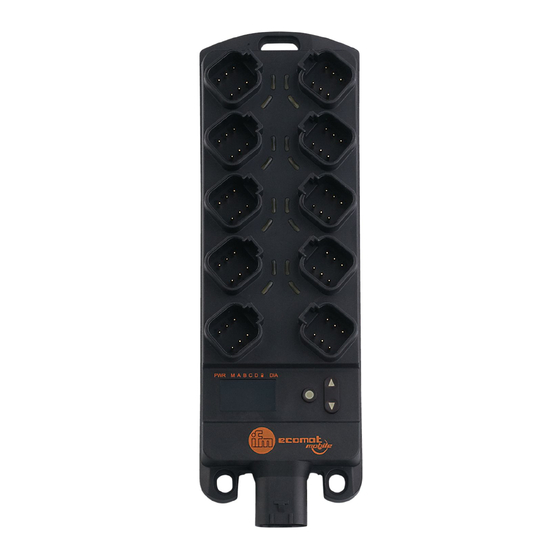
ioControl 7 Bedien- und Anzeigeelemente P_MZ_e100_0092 Original Scale Drawing (MTD) Original Scale Drawing (MTD) 1: I/O-LEDs (gelb) 2: Power-LED (grün) 3: Mode-LED (grün) 4: Applikations-LEDs LED A���LED D (grün) 5: Lock-LED (grün) 6: Diagnose-LED (rot) 7: 4-stellige 10-Segment-Anzeige Anzeigeelemente 333,4% EPS Source 10-Segment-Anzeige (→... -
Seite 15: 7�1 Menüstruktur
ioControl 7.1 Menüstruktur Die folgende Beschreibung der Menüstruktur bezieht sich auf den Ausliefer- zustand des Geräts als E/A-Modul� Wenn das Gerät als Controller einge- richtet wird, muss eine entsprechende Menüstruktur definiert werden (siehe Systemhandbuch iControl)� >10 s Node ID uLoc nodE -123 Baud rate... -
Seite 16: 7�2 Statusanzeige Der Eingänge/Ausgänge (I/O-Leds, Gelb)
ioControl 7.2 Statusanzeige der Eingänge/Ausgänge (I/O-LEDs, gelb) I/O-Konfiguration LED-Zustand Beschreibung (siehe Objektverzeichnis im Anhang) 0 (nicht benutzt) 1 (Digitaleingang B Eingangssignal FALSE Eingangssignal TRUE 2 (Digitalausgang B Ausgangssignal FALSE Ausgangssignal TRUE 3 (Spannungseingang 10 V) 4 (PWM-Ausgang) PWM = 0 PWM >... -
Seite 17: Inbetriebnahme
ioControl 8 Inbetriebnahme 8.1 E/A-Modul Im Auslieferzustand ist das Gerät als E/A-Modul konfiguriert� Nach dem Einschalten zeigt die 10-Segment-Anzeige die Artikelnummer des Ge- räts und danach die eingestellte Node-ID an� 8.1.1 Anzeigemodus Leuchtet die grüne Lock-LED, befindet sich das Gerät im Anzeigemodus� Das Ge- rät kann nur die eingestellte Node-ID und Baudrate sowie ggf�... -
Seite 18: 8�1�3 Parameterliste
ioControl > Die 1� editierbare Ziffer blinkt� ► Mit den Tasten UP und DOWN den gewünschten Wert einstellen� ► Mit der Taste ENTER zur nächsten Ziffer springen� > Die 2� editierbare Ziffer blinkt� ► Mit den Tasten UP und DOWN den gewünschten Wert einstellen� ►... -
Seite 19: 8�2 Controller
ioControl 8.2 Controller Das Gerät kann als Controller konfiguriert werden� Dadurch verliert es die bishe- rige Menüstruktur sowie die Eigenschaften als E/A-Modul� 8.2.1 Programmierung Die Applikationssoftware kann vom Anwender mit dem IEC 61131-3 konformen Programmiersystem CODESYS 2�3 erstellt werden� WARNUNG Für die sichere Funktion der vom Anwender erstellten Applikationsprogramme ist dieser selbst verantwortlich�... -
Seite 20: Technische Daten
Speicher (gesamt) 592 kByte RAM / 1536 kByte Flash / 1 kByte FRAM Speicheraufteilung siehe Systemhandbuch ioControl und www�ifm�com ifm electronic gmbh • Friedrichstraße 1 • 45128 Essen Technische Änderungen behalten wir uns ohne Ankündigung vor! CR2050 / Seite 1 15�08�2017... - Seite 21 Unterspannung konstant ein System-Fehler (Fatal Error) Bedienelemente Tasten ENTER, UP, DOWN Tasten (Voreinstellung) Einstellen der CAN-ID / Baudrate ifm electronic gmbh • Friedrichstraße 1 • 45128 Essen Technische Änderungen behalten wir uns ohne Ankündigung vor! CR2050 / Seite 2 15�08�2017...
- Seite 22 ± 2 % FS: 16 Ω...3 kΩ ± 5 % FS: 3...15 kΩ ± 10 % FS: 15...30 kΩ ifm electronic gmbh • Friedrichstraße 1 • 45128 Essen Technische Änderungen behalten wir uns ohne Ankündigung vor! CR2050 / Seite 3...
- Seite 23 Eingangswiderstand 3,2 kΩ Eingangsfrequenz 50 Hz Max� Summenstrom der CAN- 1,5 A Versorgung + Sensorversorgungen V + VBB ifm electronic gmbh • Friedrichstraße 1 • 45128 Essen Technische Änderungen behalten wir uns ohne Ankündigung vor! CR2050 / Seite 4 15�08�2017...
- Seite 24 ISO 16750-5:2010 AA, AB, BA, BD, CC, DB, DC, DD Hinweis EG-Konformitätserklärung und Zulassungen sind abrufbar unter: www�ifm�com ifm electronic gmbh • Friedrichstraße 1 • 45128 Essen Technische Änderungen behalten wir uns ohne Ankündigung vor! CR2050 / Seite 5 15�08�2017...
- Seite 25 Product Scale Drawing Frame Size: 80 mm x 90 mm Frequenz-/Impulseingang 40,5 27,4 Widerstandseingang Versorgung Sensorik/Modul Versorgung CAN-Stecker ifm electronic gmbh • Friedrichstraße 1 • 45128 Essen Technische Änderungen behalten wir uns ohne Ankündigung vor! CR2050 / Seite 6 15�08�2017...
-
Seite 26: 9�2 Cr2051
Speicher (gesamt) 592 kByte RAM / 1536 kByte Flash / 1 kByte FRAM Speicheraufteilung siehe Systemhandbuch ioControl und www�ifm�com ifm electronic gmbh • Friedrichstraße 1 • 45128 Essen Technische Änderungen behalten wir uns ohne Ankündigung vor! CR2051 / Seite 1 15�08�2017... - Seite 27 10 Hz Applikation angehalten (STOP mit Fehler) 5 Hz Applikation angehalten wegen Unterspannung konstant ein System-Fehler (Fatal Error) ifm electronic gmbh • Friedrichstraße 1 • 45128 Essen Technische Änderungen behalten wir uns ohne Ankündigung vor! CR2051 / Seite 2 15�08�2017...
- Seite 28 ● Stromgeregelter Ausgang Ausgangsfrequenz 20���250 Hz Regelbereich 0,02���2,5 A Einstellaufl ösung 1 mA Max� Einschaltstrom ≤ 24 A ifm electronic gmbh • Friedrichstraße 1 • 45128 Essen Technische Änderungen behalten wir uns ohne Ankündigung vor! CR2051 / Seite 3 15�08�2017...
- Seite 29 (gültig für alle Ein- und Ausgänge) Max� Summenstrom der CAN- 1,5 A Versorgung V Max� Summenstrom der Ausgangsversorgungen VBB / VBB ifm electronic gmbh • Friedrichstraße 1 • 45128 Essen Technische Änderungen behalten wir uns ohne Ankündigung vor! CR2051 / Seite 4 15�08�2017...
- Seite 30 ISO 16750-5:2010 AA, AB, BA, BD, CC, DB, DC, DD Hinweis EG-Konformitätserklärung und Zulassungen sind abrufbar unter: www�ifm�com ifm electronic gmbh • Friedrichstraße 1 • 45128 Essen Technische Änderungen behalten wir uns ohne Ankündigung vor! CR2051 / Seite 5 15�08�2017...
- Seite 31 Versorgung OUT00, OUT02, OUT04, OUT06, OUT08, OUT10, OUT12, OUT14 Versorgung OUT01, OUT03, OUT05, OUT07, OUT09, OUT11, OUT13, OUT15 Versorgung CAN-Stecker ifm electronic gmbh • Friedrichstraße 1 • 45128 Essen Technische Änderungen behalten wir uns ohne Ankündigung vor! CR2051 / Seite 6 15�08�2017...
-
Seite 32: 9�3 Cr2052
Speicher (gesamt) 592 kByte RAM / 1536 kByte Flash / 1 kByte FRAM Speicheraufteilung siehe Systemhandbuch ioControl und www�ifm�com ifm electronic gmbh • Friedrichstraße 1 • 45128 Essen Technische Änderungen behalten wir uns ohne Ankündigung vor! CR2052 / Seite 1 15�08�2017... - Seite 33 1 x LED rot (Voreinstellung: Anzeigen eines Fehlers) Anzeige 4-stellige 10-Segment-Anzeige (zweifarbig: rot / grün) (Voreinstellung: Anzeige der Baudrate oder Node-ID) ifm electronic gmbh • Friedrichstraße 1 • 45128 Essen Technische Änderungen behalten wir uns ohne Ankündigung vor! CR2052 / Seite 2 15�08�2017...
- Seite 34 50 Hz ● Frequenzeingänge Eingangswiderstand 3,2 kΩ Eingangsfrequenz ≤ 30 kHz Einschaltpegel > 0,7 U Ausschaltpegel < 0,3 U ifm electronic gmbh • Friedrichstraße 1 • 45128 Essen Technische Änderungen behalten wir uns ohne Ankündigung vor! CR2052 / Seite 3 15�08�2017...
- Seite 35 ● Stromgeregelter Ausgang Ausgangsfrequenz 20���250 Hz Regelbereich 0,02���4 A Einstellaufl ösung 1 mA Max� Einschaltstrom ≤ 24 A ifm electronic gmbh • Friedrichstraße 1 • 45128 Essen Technische Änderungen behalten wir uns ohne Ankündigung vor! CR2052 / Seite 4 15�08�2017...
- Seite 36 (gültig für alle Ein- und Ausgänge) Max� Summenstrom der CAN- 1,5 A Versorgung + Sensorversorgungen V + VBB Max� Summenstrom der Ausgangsversorgungen VBB ifm electronic gmbh • Friedrichstraße 1 • 45128 Essen Technische Änderungen behalten wir uns ohne Ankündigung vor! CR2052 / Seite 5 15�08�2017...
- Seite 37 ISO 16750-5:2010 AA, AB, BA, BD, CC, DB, DC, DD Hinweis EG-Konformitätserklärung und Zulassungen sind abrufbar unter: www�ifm�com ifm electronic gmbh • Friedrichstraße 1 • 45128 Essen Technische Änderungen behalten wir uns ohne Ankündigung vor! CR2052 / Seite 6 15�08�2017...
- Seite 38 Frame Size: 80 mm x 90 mm 40,5 Binär High-Side 27,4 Binär Low-Side Pulsweitenmodulation Pulsweitenmodulation, stromgeregelt Versorgung Sensorik/Modul Versorgung OUT01���OUT07 Versorgung CAN-Stecker ifm electronic gmbh • Friedrichstraße 1 • 45128 Essen Technische Änderungen behalten wir uns ohne Ankündigung vor! CR2052 / Seite 7 15�08�2017...
-
Seite 39: Wartung, Instandsetzung Und Entsorgung
ioControl 10 Wartung, Instandsetzung und Entsorgung 10.1 Wartung Das Gerät enthält keine vom Anwender zu wartenden Bauteile� 10.2 Reinigen der Gehäuseoberfläche ► Gerät von der Betriebsspannung trennen� ► Verschmutzungen mit einem weichen, chemisch unbehandelten und trockenen Tuch entfernen� ► Bei starker Verschmutzung ein feuchtes Tuch verwenden� Folgende Mittel sind zur Gerätereinigung ungeeignet: Kunststofflösende Chemikalien, wie z�B�... -
Seite 40: Appendix
ioControl 12 Appendix 12.1 EMCY Object The following error codes according to DSP-401 or DSP-301 are supported: EMCY code Error reg Additional code Description 0x6100 0x11 0x00 Internal Software Overflow of an Rx queue e�g� frequency of the Rx PDOs is too high� Reset only externally via entry in the index 0x1003 SubIdx 00�... - Seite 41 0x1006 Communi- UDINT Max� time between 2 synch objects cation cycle in [µs] period Control resolution = 1 ms 0x1008 Manufacturer STRING CR205x Device designation (CR2050 or device name CR2051 or CR2052) 0x1009 Manufacturer STRING V00�00�00 Hardware version hardware version...
- Seite 42 ioControl Index S-idx Designation Data type Default Details 0x100A Manufacturer STRING V00�00�00 Software version software version 0x100C Guard time UINT Within this time in [ms] the device expects a „node guarding“ of the master oft he system� 0 = this function is not supported� The monitoring oft he node with „node guarding“...
- Seite 43 ioControl Index S-idx Designation Data type Default Details 0x1016 0x00 Consumer USINT 0x01 Heartbeat monitoring time for the heartbeat node times Number of devices monitored = 1 Nums consumer heartbeat time 0x01 Consumer UDINT Heartbeat monitoring time for the heartbeat node time Format: 0x0nntttt...
-
Seite 44: 12�2�1 Device-Specific Cr2050
ioControl 12.2.1 Device-specific CR2050 Transmit PDO communication parameters (index 0x1800…0x18FF): Index S-idx Designation Data type Default Details 0x1800 0x00 Transmit USINT 0x05 Configuration transmit PDO 1 PDO Com- number of entries = 5 munication Parameter Number of entries 0x01 COBID used UDINT 0x180 + CAN ID of the transmit PDO 1... - Seite 45 ioControl Index S-idx Designation Data type Default Details 0x1801 0x00 Transmit USINT 0x05 Configuration transmit PDO 2 PDO Com- number of entries = 5 munication Parameter Number of entries 0x01 COBID used UDINT 0x280 + CAN ID of the transmit PDO 2 by PDO Node ID Bit 31 = 0 →...
- Seite 46 ioControl Index S-idx Designation Data type Default Details 0x1802 0x00 Transmit USINT 0x05 Configuration transmit PDO 3 PDO Com- number of entries = 5 munication Parameter Number of entries 0x01 COBID used UDINT 0x380 + CAN ID of the transmit PDO 3 by PDO Node ID Bit 31 = 0 →...
- Seite 47 ioControl Index S-idx Designation Data type Default Details 0x1803 0x00 Transmit USINT 0x05 Configuration transmit PDO 4 PDO Com- number of entries = 5 munication Parameter Number of entries 0x01 COBID used UDINT 0x480 + CAN ID of the transmit PDO 4 by PDO Node ID Bit 31 = 0 →...
- Seite 48 ioControl Index S-idx Designation Data type Default Details 0x1804 0x00 Transmit USINT 0x05 Configuration transmit PDO 5 PDO Com- number of entries = 5 munication Parameter Number of entries 0x01 COBID used UDINT 0x181 + CAN ID of the transmit PDO 5 by PDO Node ID Bit 31 = 0 →...
- Seite 49 ioControl Index S-idx Designation Data type Default Details 0x1805 0x00 Transmit USINT 0x05 Configuration transmit PDO 6 PDO Com- number of entries = 5 munication Parameter Number of entries 0x01 COBID used UDINT 0x281 + CAN ID of the transmit PDO 6 by PDO Node ID Bit 31 = 0 →...
- Seite 50 ioControl Index S-idx Designation Data type Default Details 0x1806 0x00 Transmit USINT 0x05 Configuration transmit PDO 7 PDO Com- number of entries = 5 munication Parameter Number of entries 0x01 COBID used UDINT 0x381 + CAN ID of the transmit PDO 7 by PDO Node ID Bit 31 = 0 →...
- Seite 51 ioControl Index S-idx Designation Data type Default Details 0x1807 0x00 Transmit USINT 0x05 Configuration transmit PDO 8 PDO Com- number of entries = 5 munication Parameter Number of entries 0x01 COBID used UDINT 0x481 + CAN ID of the transmit PDO 8 by PDO Node ID Bit 31 = 0 →...
- Seite 52 ioControl Index S-idx Designation Data type Default Details 0x1808 0x00 Transmit USINT 0x05 Configuration transmit PDO 9 PDO Com- number of entries = 5 munication Parameter Number of entries 0x01 COBID used UDINT 0x182 + CAN ID of the transmit PDO 9 by PDO Node ID Bit 31 = 0 →...
- Seite 53 ioControl Index S-idx Designation Data type Default Details 0x1809 0x00 Transmit USINT 0x05 Configuration transmit PDO 10 PDO Com- number of entries = 5 munication Parameter Number of entries 0x01 COBID used UDINT 0x282 + CAN ID of the transmit PDO 10 by PDO Node ID Bit 31 = 0 →...
- Seite 54 ioControl Transmit PDO mapping (index 0x1A00…0x1AFF): Index S-idx Designation Data type Default Details 0x1A00 0x00 Transmit USINT 0x07 mapping transmit PDO 1 PDO map- number of integrated application ping objects = 7 Number of mapped objects in 0x01 PDO map- UDINT 0x6000 0108 Index 0x6000, SubIndex 0x01...
- Seite 55 ioControl Index S-idx Designation Data type Default Details 0x1A01 0x00 Transmit USINT 0x04 mapping transmit PDO 2 (analogue PDO map- inputs) ping number of integrated application Number of objects = 4 mapped objects in 0x01 PDO map- UDINT 0x6404 0110 Index 0x6404, SubIndex 0x01 ping analogue input 00: actual value...
- Seite 56 ioControl Index S-idx Designation Data type Default Details 0x1A03 0x00 Transmit USINT 0x04 mapping transmit PDO 4 PDO map- number of integrated application ping objects = 4 Number of mapped objects in 0x01 PDO map- UDINT 0x2030 0110 Index 0x2030, SubIndex 0x01 ping input 08: actual resistor value 0x02...
- Seite 57 ioControl Index S-idx Designation Data type Default Details 0x1A06 0x00 Transmit USINT 0x04 mapping transmit PDO 7 (duty cycle PDO map- of the signal on the frequency input ping IN09, IN11, IN13, IN15) Number of number of integrated application mapped objects = 4 objects in 0x01...
- Seite 58 ioControl Index S-idx Designation Data type Default Details 0x1A09 0x00 Transmit USINT 0x02 mapping transmit PDO 10 (system PDO map- flag) ping number of integrated application Number of objects = 2 mapped objects in 0x01 PDO map- UDINT 0x2040 0110 Index 0x2040, SubIndex 0x01 ping supply voltage of the system VBBS...
- Seite 59 ioControl Index S-idx Designation Data type Default Details 0x2000 0x04 Configuration USINT 0 = 0x00 off Input IN03 IN03 3 = 0x03 0���10 000 mV 6 = 0x06 ratiometric 0���1000 ‰ 7 = 0x07 0���20 000 µA 9 = 0x09 0���32 000 mV 10 = 0x0A binary plus switched...
- Seite 60 ioControl Index S-idx Designation Data type Default Details 0x2000 0x0A Configuration USINT 0 = 0x00 off Input IN09 IN09 01 = 0x01 binary plus switched 14 = 0x0E frequency 0…30 20 = 0x14 000 Hz period duration 0x0B Configuration USINT 0 = 0x00 off Input IN10 IN10...
- Seite 61 ioControl Index S-idx Designation Data type Default Details 0x2013 0x00 Period input USINT Largest sub-index supported number of periods for average 0x01 Number of USINT 1…255 IN09 number of periods IN09 periods 0x02 Number of USINT 1…255 IN11 number of periods IN11 periods 0x03...
- Seite 62 ioControl Index S-idx Designation Data type Default Details 0x2020 0x00 Input – short USINT Largest sub-index supported to supply voltage 0x01 Short to sup- USINT 0 = normal channels (bit coded) ply voltage 1 = short 0b---- ---X = IN00 IN00���IN07 circuit 0b---- --X- = IN01...
- Seite 63 ioControl Index S-idx Designation Data type Default Details 0x2030 0x00 Input resistor USINT Largest sub-index supported 0x01 Resistance UINT 0…30 000 IN08 resistance IN08 [Ohms] 0x02 Resistance UINT 0…30 000 IN10 resistance IN10 [Ohms] 0x03 Resistance UINT 0…30 000 IN12 resistance IN12 [Ohms] 0x04...
- Seite 64 ioControl Index S-idx Designation Data type Default Details 0x6000 0x00 Binary input USINT 0x02 Binary inputs Largest Largest supported sub-index = 2 sub-index supported 0x01 Binary inputs USINT Binary inputs IN00…IN07 IN00 - IN07 0b---- ---X = IN00 0b---- --X- = IN01 0b---- -X-- = IN02 0b---- X--- = IN03 0b---X ---- = IN04...
-
Seite 65: 12�2�2 Device-Specific Cr2051
12.2.2 Device-specific CR2051 Receive PDO communication parameters (index 0x1400…0x14FF): Index S-idx Designation Data type Default Details 0x1400 0x00 Receive PDO USINT 0x02 Receive PDO 1: binary outputs 0 - 15 Communica- number of entries = 2 tion Parame- ter Number of... - Seite 66 ioControl Index S-idx Designation Data type Default Details 0x1402 0x00 Receive PDO USINT 0x02 Receive PDO 3: PWM outputs 4 - 7 Communica- number of entries = 2 tion Parame- ter Number of entries 0x01 COBID used UDINT 0x400 + node CAN-ID of the 3�...
- Seite 67 ioControl Index S-idx Designation Data type Default Details 0x1404 0x00 Receive PDO USINT 0x02 Receive PDO 5: PWM outputs 12 Communica- - 15 tion Parame- number of entries = 2 ter Number of entries 0x01 COBID used UDINT 0x201 + node CAN-ID of the 3�...
- Seite 68 ioControl Index S-idx Designation Data type Default Details 0x1601 0x00 Receive PDO USINT 0x04 Mapping read PDO 2: mapping PWM outputs OUT00…OUT03 Number of number of integrated application mapped objects = 4 objects in 0x01 PDO map- UDINT 0x6414 0110 PWM/current output OUT00 ping Index 0x6414, SubIndex 0x01...
- Seite 69 ioControl Index S-idx Designation Data type Default Details 0x1602 0x00 "Receive USINT 0x04 Mapping read PDO 3: PDO map- PWM outputs OUT04…OUT07 ping number of integrated application Number of objects = 4 mapped objects in PDO" 0x01 PDO map- UDINT 0x6414 0510 PWM/ current output OUT04 ping...
- Seite 70 ioControl Index S-idx Designation Data type Default Details 0x1603 0x00 Receive PDO USINT 0x04 Mapping read PDO 4: mapping PWM outputs OUT08…OUT11 Number of number of integrated application mapped objects = 4 objects in 0x01 PDO map- UDINT 0x6414 0910 PWM/ current output OUT08 ping Index 0x6414, SubIndex 0x09...
- Seite 71 ioControl Index S-idx Designation Data type Default Details 0x1604 0x00 Receive PDO USINT 0x04 Mapping read PDO 5: mapping PWM outputs OUT12…OUT15 Number of number of integrated application mapped objects = 4 objects in 0x01 PDO map- UDINT 0x6414 0D10 PWM/ current output OUT12 ping Index 0x6414, SubIndex 0x0D...
- Seite 72 ioControl Transmit PDO communication parameters (index 0x1800…0x18FF): Index S-idx Designation Data type Default Details 0x1800 0x00 Transmit USINT 0x05 Configuration transmit PDO 1 PDO Com- number of entries = 5 munication Parameter Number of entries 0x01 COBID used UDINT 0x180 + CAN ID of the transmit PDO 1 by PDO Node ID...
- Seite 73 ioControl Index S-idx Designation Data type Default Details 0x1801 0x00 Transmit USINT 0x05 Configuration transmit PDO 2 PDO Com- number of entries = 5 munication Parameter Number of entries 0x01 COBID used UDINT 0x280 + CAN ID of the transmit PDO 2 by PDO Node ID Bit 31 = 0 →...
- Seite 74 ioControl Index S-idx Designation Data type Default Details 0x1802 0x00 Transmit USINT 0x05 Configuration transmit PDO 3 PDO Com- number of entries = 5 munication Parameter Number of entries 0x01 COBID used UDINT 0x380 + CAN ID of the transmit PDO 3 by PDO Node ID Bit 31 = 0 →...
- Seite 75 ioControl Index S-idx Designation Data type Default Details 0x1803 0x00 Transmit USINT 0x05 Configuration transmit PDO 4 PDO Com- number of entries = 5 munication Parameter Number of entries 0x01 COBID used UDINT 0x480 + CAN ID of the transmit PDO 4 by PDO Node ID Bit 31 = 0 →...
- Seite 76 ioControl Transmit PDO mapping (index 0x1A00…0x1AFF): Index S-idx Designation Data type Default Details 0x1A00 0x00 Transmit USINT 0x04 mapping transmit PDO 01 (output PDO map- current OUT00���OUT03) ping number of integrated application Number of objects = 4 mapped objects in 0x01 PDO map- UDINT...
- Seite 77 ioControl Index S-idx Designation Data type Default Details 0x1A02 0x00 Transmit USINT 0x05 mapping transmit PDO 3 PDO map- number of integrated application ping objects = 5 Number of mapped objects in 0x01 PDO map- UDINT 0x2022 0108 Index 0x2022, SubIndex 0x01 ping outputs 00���07: flag "...
- Seite 78 ioControl Manufacturer-specific objekts (index 0x2000���0x6FFF): Index S-idx Designation Data type Default Details 0x2000 0x00 IO configu- USINT Configuration inputs/outputs ration largest supported Sub-index = 32 Largest sub-index supported 0x01 Configuration USINT 0 = 0x00 off Input OUT00 OUT00 2 = 0x02 binary plus switched 4 = 0x04 PWM output...
- Seite 79 ioControl Index S-idx Designation Data type Default Details 0x2000 0x06 Configuration USINT 0 = 0x00 off Input OUT05 OUT05 2 = 0x02 binary plus switched 4 = 0x04 PWM output 5 = 0x05 current control 15 = 0x0F binary plus switched 16 = 0x10 with diagnosis binary plus switched...
- Seite 80 ioControl Index S-idx Designation Data type Default Details 0x2000 0x0E Configuration USINT 0 = 0x00 off Input OUT13 OUT13 2 = 0x02 binary plus switched 4 = 0x04 PWM output 15 = 0x0F binary plus switched with diagnosis 0x0F Configuration USINT 0 = 0x00 off Input OUT14...
- Seite 81 ioControl Index S-idx Designation Data type Default Details 0x2001 0x0B UINT 20…250 OUT10 PWM frequen- frequency cy [Hz] OUT10 0x0C UINT 20…250 OUT11 PWM frequen- frequency cy [Hz] OUT11 0x0D UINT 20…250 OUT12 PWM frequen- frequency cy [Hz] OUT12 0x0E UINT 20…250 OUT13 PWM frequen-...
- Seite 82 ioControl Index S-idx Designation Data type Default Details 0x2004 0x00 P-value USINT Largest sub-index supported 0x01 P-value USINT 0…255 OUT00 P-value for OUT00 current control 0x02 P-value USINT 0…255 OUT01 P-value for OUT01 current control 0x03 P-value USINT 0…255 OUT02 P-value for OUT02 current control 0x04...
- Seite 83 ioControl Index S-idx Designation Data type Default Details 0x2006 0x03 PWM dither UINT 0…PWM- OUT02 PWM dither frequency freq / 2 frequency [Hz] OUT02 0x04 PWM dither UINT 0…PWM- OUT03 PWM dither frequency freq / 2 frequency [Hz] OUT03 0x05 PWM dither UINT 0…PWM-...
- Seite 84 ioControl Index S-idx Designation Data type Default Details 0x2007 0x00 PWM dither USINT Largest sub-index supported value 0x01 PWM dither UINT 0…1 000 OUT00 PWM dither value OUT00 value [‰] 0x02 PWM dither UINT 0…1 000 OUT01 PWM dither value OUT01 value [‰] 0x03 PWM dither...
- Seite 85 ioControl Index S-idx Designation Data type Default Details 0x2022 0x00 Output – USINT Largest sub-index supported short circuit 0x01 Short circuit USINT 0 = normal channels (bit coded) OUT00… 1 = short 0b---- ---X = OUT00 OUT07 circuit 0b---- --X- = OUT01 0b---- -X-- = OUT02 0b---- X--- = OUT03 0b---X ---- = OUT04...
- Seite 86 ioControl Index S-idx Designation Data type Default Details 0x2040 0x00 System supp- USINT Largest sub-index supported ly voltage VBBS 0x01 VBBS USINT VBBS voltage [mV] 0x2041 0x00 Output supp- USINT Largest sub-index supported ly voltage 0x01 VBB1 UINT VBB1 voltage [mV] 0x02 VBB2 UINT...
- Seite 87 ioControl Index S-idx Designation Data type Default Details 0x6200 0x00 Binary output USINT Binary outputs Largest Largest supported sub-index = 2 sub-index supported 0x01 Binary out- USINT Binary outputs OUT00…OUT07 puts OUT00 0b---- ---X = OUT00 - OUT07 0b---- --X- = OUT01 0b---- -X-- = OUT02 0b---- X--- = OUT03 0b---X ---- = OUT04...
- Seite 88 ioControl Index S-idx Designation Data type Default Details 0x6414 0x00 PWM output USINT PWM outputs Largest Largest supported sub-index = 16 sub-index supported 0x01 PWM output UINT Value for PWM output OUT00 OUT00 0x02 PWM output UINT Value for PWM output OUT01 OUT01 0x03 PWM output...
-
Seite 89: 12�2�3 Device-Specific Cr2052
ioControl 12.2.3 Device-specific CR2052 Receive PDO communication parameters (index 0x1400…0x14FF): Index S-idx Designation Data type Default Details 0x1400 0x00 Receive PDO USINT 0x02 Receive PDO 1: binary outputs 0 - 7 Communica- number of entries = 2 tion Parame- ter Number of entries 0x01 COBID used... - Seite 90 ioControl Index S-idx Designation Data type Default Details 0x1402 0x00 Receive PDO USINT 0x02 Receive PDO 3: PWM outputs 4 - 7 Communica- number of entries = 2 tion Parame- ter Number of entries 0x01 COBID used UDINT 0x400 + node CAN-ID of the 3�...
- Seite 91 ioControl Index S-idx Designation Data type Default Details 0x1601 0x00 Receive PDO USINT 0x04 Mapping read PDO 2: mapping PWM outputs OUT00…OUT03 Number of number of integrated application mapped objects = 4 objects in 0x01 PDO map- UDINT 0x6414 0110 PWM/current output OUT00 ping Index 0x6414, SubIndex 0x01...
- Seite 92 ioControl Index S-idx Designation Data type Default Details 0x1602 0x00 Receive PDO USINT 0x04 Mapping read PDO 3: mapping PWM outputs OUT04…OUT07 Number of number of integrated application mapped objects = 4 objects in 0x01 PDO map- UDINT 0x6414 0510 PWM/ current output OUT04 ping Index 0x6414, SubIndex 0x05...
- Seite 93 ioControl Transmit PDO communication parameters (index 0x1800…0x18FF): Index S-idx Designation Data type Default Details 0x1800 0x00 Transmit USINT 0x05 Configuration transmit PDO 1 PDO Com- number of entries = 5 munication Parameter Number of entries 0x01 COBID used UDINT 0x180 + CAN ID of the transmit PDO 1 by PDO Node ID...
- Seite 94 ioControl Index S-idx Designation Data type Default Details 0x1801 0x00 Transmit USINT 0x05 Configuration transmit PDO 2 PDO Com- number of entries = 5 munication Parameter Number of entries 0x01 COBID used UDINT 0x280 + CAN ID of the transmit PDO 2 by PDO Node ID Bit 31 = 0 →...
- Seite 95 ioControl Index S-idx Designation Data type Default Details 0x1802 0x00 Transmit USINT 0x05 Configuration transmit PDO 3 PDO Com- number of entries = 5 munication Parameter Number of entries 0x01 COBID used UDINT 0x380 + CAN ID of the transmit PDO 3 by PDO Node ID Bit 31 = 0 →...
- Seite 96 ioControl Index S-idx Designation Data type Default Details 0x1803 0x00 Transmit USINT 0x05 Configuration transmit PDO 4 PDO Com- number of entries = 5 munication Parameter Number of entries 0x01 COBID used UDINT 0x480 + CAN ID of the transmit PDO 4 by PDO Node ID Bit 31 = 0 →...
- Seite 97 ioControl Index S-idx Designation Data type Default Details 0x1804 0x00 Transmit USINT 0x05 Configuration transmit PDO 5 PDO Com- number of entries = 5 munication Parameter Number of entries 0x01 COBID used UDINT 0x181 + CAN ID of the transmit PDO 5 by PDO Node ID Bit 31 = 0 →...
- Seite 98 ioControl Index S-idx Designation Data type Default Details 0x1805 0x00 Transmit USINT 0x05 Configuration transmit PDO 6 PDO Com- number of entries = 5 munication Parameter Number of entries 0x01 COBID used UDINT 0x281 + CAN ID of the transmit PDO 6 by PDO Node ID Bit 31 = 0 →...
- Seite 99 ioControl Index S-idx Designation Data type Default Details 0x1806 0x00 Transmit USINT 0x05 Configuration transmit PDO 7 PDO Com- number of entries = 5 munication Parameter Number of entries 0x01 COBID used UDINT 0x381 + CAN ID of the transmit PDO 7 by PDO Node ID Bit 31 = 0 →...
- Seite 100 ioControl Index S-idx Designation Data type Default Details 0x1807 0x00 Transmit USINT 0x05 Configuration transmit PDO 8 PDO Com- number of entries = 5 munication Parameter Number of entries 0x01 COBID used UDINT 0x481 + CAN ID of the transmit PDO 8 by PDO Node ID Bit 31 = 0 →...
- Seite 101 ioControl Index S-idx Designation Data type Default Details 0x1808 0x00 Transmit USINT 0x05 Configuration transmit PDO 9 PDO Com- number of entries = 5 munication Parameter Number of entries 0x01 COBID used UDINT 0x182 + CAN ID of the transmit PDO 9 by PDO Node ID Bit 31 = 0 →...
- Seite 102 ioControl Index S-idx Designation Data type Default Details 0x1809 0x00 Transmit USINT 0x05 Configuration transmit PDO 10 PDO Com- number of entries = 5 munication Parameter Number of entries 0x01 COBID used UDINT 0x282 + CAN ID of the transmit PDO 10 by PDO Node ID Bit 31 = 0 →...
- Seite 103 ioControl Index S-idx Designation Data type Default Details 0x180A 0x00 Transmit USINT 0x05 Configuration transmit PDO 11 PDO Com- number of entries = 5 munication Parameter Number of entries 0x01 COBID used UDINT 0x382 + CAN ID of the transmit PDO 11 by PDO Node ID Bit 31 = 0 →...
- Seite 104 ioControl Transmit PDO mapping (index 0x1A00…0x1AFF): Index S-idx Designation Data type Default Details 0x1A00 0x00 Transmit USINT 0x07 mapping transmit PDO 1 PDO map- number of integrated application ping objects = 7 Number of mapped objects in 0x01 PDO map- UDINT 0x6000 0108 Index 0x6000, SubIndex 0x01...
- Seite 105 ioControl Index S-idx Designation Data type Default Details 0x1A01 0x00 Transmit USINT 0x04 mapping transmit PDO 2 (analogue PDO map- inputs) ping number of integrated application Number of objects = 4 mapped objects in 0x01 PDO map- UDINT 0x6404 0110 Index 0x6404, SubIndex 0x01 ping analogue input 00: actual value...
- Seite 106 ioControl Index S-idx Designation Data type Default Details 0x1A03 0x00 Transmit USINT 0x02 mapping transmit PDO 4 (periode PDO map- time IN00���IN01) ping number of integrated application Number of objects = 2 mapped objects in 0x01 PDO map- UDINT 0x2012 0120 Index 0x2012, SubIndex 0x01 ping frequency input IN00: periode time of...
- Seite 107 ioControl Index S-idx Designation Data type Default Details 0x1A06 0x00 Transmit USINT 0x02 mapping transmit PDO 7 (frequency PDO map- on IN00���IN01) ping number of integrated application Number of objects = 2 mapped objects in 0x01 PDO map- UDINT 0x2015 0120 Index 0x2015, SubIndex 0x01 ping frequency input IN00: frequency...
- Seite 108 ioControl Index S-idx Designation Data type Default Details 0x1A09 0x00 Transmit USINT 0x04 mapping transmit PDO 10 (output PDO map- current OUT04���OUT07) ping number of integrated application Number of objects = 4 mapped objects in 0x01 PDO map- UDINT 0x2002 0510 Index 0x2002, SubIndex 0x05 ping current on output OUT04...
- Seite 109 ioControl Manufacturer-specific objekts (index 0x2000���0x6FFF): Index S-idx Designation Data type Default Details 0x2000 0x00 IO configu- USINT Configuration inputs/outputs ration largest supported Sub-index = 32 Largest sub-index supported 0x01 Configuration USINT 0 = 0x00 off Input IN00 IN00 3 = 0x03 0���10 000 mV 6 = 0x06 ratiometric 0���1000 ‰...
- Seite 110 ioControl Index S-idx Designation Data type Default Details 0x2000 0x05 Configuration USINT 0 = 0x00 off Input IN04 IN04 3 = 0x03 0���10 000 mV 6 = 0x06 ratiometric 0���1000 ‰ 7 = 0x07 0���20 000 µA 9 = 0x09 0���32 000 mV 10 = 0x0A binary plus switched...
- Seite 111 ioControl Index S-idx Designation Data type Default Details 0x2000 0x0A Configuration USINT 0 = 0x00 off Output OUT01 OUT01 2 = 0x02 binary plus switched 4 = 0x04 PWM output 5 = 0x05 current control 15 = 0x0F binary plus switched 16 = 0x10 with diagnosis binary plus switched...
- Seite 112 ioControl Index S-idx Designation Data type Default Details 0x2000 0x0F Configuration USINT 0 = 0x00 off Output OUT06 OUT06 2 = 0x02 binary plus switched 4 = 0x04 PWM output 5 = 0x05 current control 15 = 0x0F binary plus switched 16 = 0x10 with diagnosis binary plus switched...
- Seite 113 ioControl Index S-idx Designation Data type Default Details 0x2002 0x00 Current value USINT Largest sub-index supported 0x01 Current value UINT 0…4000 OUT00 output current OUT00 [mA] 0x02 Current value UINT 0…4000 OUT01 output current OUT01 [mA] 0x03 Current value UINT 0…2500 OUT02 output current OUT02...
- Seite 114 ioControl Index S-idx Designation Data type Default Details 0x2005 0x00 I-value USINT Largest sub-index supported 0x01 I-value USINT 0…255 OUT00 I-value for OUT00 current control 0x02 I-value USINT 0…255 OUT01 I-value for OUT01 current control 0x03 I-value USINT 0…255 OUT02 I-value for OUT02 current control 0x04...
- Seite 115 ioControl Index S-idx Designation Data type Default Details 0x2007 0x00 PWM dither USINT Largest sub-index supported value 0x01 PWM dither UINT 0…1 000 OUT00 PWM dither value OUT00 value [‰] 0x02 PWM dither UINT 0…1 000 OUT01 PWM dither value OUT01 value [‰] 0x03 PWM dither...
- Seite 116 ioControl Index S-idx Designation Data type Default Details 0x2014 0x00 Period input USINT Largest sub-index supported – ratio value 0x01 Period ratio UINT 0…1 000 IN00 marc-to-space value IN00 ratio [‰] 0x02 Period ratio UINT 0…1 000 IN01 marc-to-space value IN01 ratio [‰] 0x03 Period ratio...
- Seite 117 ioControl Index S-idx Designation Data type Default Details 0x2021 0x00 Input – wire USINT Largest sub-index supported break 0x01 Wire break USINT 0 = normal channels (bit coded) IN00���IN07 1 = wire 0b---- ---X = IN00 break 0b---- --X- = IN01 0b---- -X-- = IN02 0b---- X--- = IN03 0b---X ---- = IN04...
- Seite 118 ioControl Index S-idx Designation Data type Default Details 0x2025 0x00 Input analog USINT Largest sub-index supported – overcurrent 0x01 Overcur- USINT 0 = normal channels (bit coded) rent IN00, 1 = overcur- 0b---- ---X = IN00 IN01,N04 rent 0b---- --X- = IN01 und IN05 0b---- -X-- = IN04 0b---- X--- = IN05...
- Seite 119 ioControl Index S-idx Designation Data type Default Details 0x20F3 Baud rate USINT baud rate [!] value(0x20F2) != value(20F3) 0x20F4 Autostart UINT not used 0x20F5 Lock edit USINT 0 = edit mode unlocked mode 1 = edit mode locked 0x6000 0x00 Binary input USINT 0x02...
- Seite 120 ioControl Index S-idx Designation Data type Default Details 0x6414 0x00 PWM output USINT 0x08 PWM outputs Largest Largest supported sub-index = 12 sub-index supported 0x01 PWM output UINT Value for PWM output OUT00 OUT00 0x02 PWM output UINT Value for PWM output OUT01 OUT01 0x03 PWM output...
-
Seite 121: 12�3 Sdos Error Messages
ioControl 12.3 SDOs error messages 12.3.1 CR2050 The following messages are created in case of an error: Index S-idx Designation Data type Default Details 0x1001 Error register USINT Error register bitcodiert to profil 301 permissible values: 0b0000 0000 = no error 0b0000 0001 = generic error 0b0001 0000 = communication error 0b1000 0000 = manufacturer specific... - Seite 122 ioControl Index S-idx Designation Data type Default Details 0x2021 0x00 Input – wire break USINT Largest sub-index supported 0x01 Wire break IN00��� USINT 0 = normal channels (bit coded) IN07 1 = wire break 0b---- ---X = IN00 0b---- --X- = IN01 0b---- -X-- = IN02 0b---- X--- = IN03 0b---X ---- = IN04...
-
Seite 123: 12�3�2 Cr2051
12.3.2 CR2051 The following messages are created in case of an error: Index S-idx Designation Data type Default Details 0x1001 Error register USINT Error register bitcodiert to profil 301 permissible values: 0b0000 0000 = no error 0b0000 0001 = generic error... - Seite 124 ioControl Index S-idx Designation Data type Default Details 0x2023 0x00 Output – open USINT Largest sub-index supported circuit 0x01 Open circuit USINT 0 = normal channels (bit coded) OUT00…OUT07 1 = open circuit 0b---- ---X = OUT00 0b---- --X- = OUT01 0b---- -X-- = OUT02 0b---- X--- = OUT03 0b---X ---- = OUT04...
-
Seite 125: 12�3�3 Cr2052
ioControl 12.3.3 CR2052 The following messages are created in case of an error: Index S-idx Designation Data type Default Details 0x1001 Error register USINT Error register bitcodiert to profil 301 permissible values: 0b0000 0000 = no error 0b0000 0001 = generic error 0b0001 0000 = communication error 0b1000 0000 = manufacturer specific 0x1003... - Seite 126 ioControl Index S-idx Designation Data type Default Details 0x2022 0x00 Output – short USINT Largest sub-index supported circuit 0x01 Short circuit USINT 0 = normal channels (bit coded) OUT00…OUT07 1 = short circuit 0b---- ---X = OUT00 0b---- --X- = OUT01 0b---- -X-- = OUT02 0b---- X--- = OUT03 0b---X ---- = OUT04...