
Verwandte Anleitungen für IFM Electronic ecomot100 PDM360 smart


Inhaltszusammenfassung für IFM Electronic ecomot100 PDM360 smart
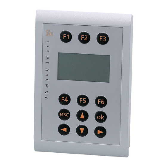
- Seite 1 Montageanleitung Installation instructions Prozess- und Dialoggerät PDM 360 smart Process and dialogue module PDM 360 smart CR1070 CR1071...
-
Seite 2: Sicherheitshinweise
An den Anschlusssteckern dürfen nur die in den technischen Daten, bzw. auf dem Geräteaufdruck angegebenen Signale eingespeist bzw. die zugelassenen Zu- behörkomponenten der ifm electronic gmbh angeschlossen werden. Schalten Sie alle Geräte extern spannungsfrei bevor Sie irgendwelche Arbeiten an ihnen vornehmen. Schalten Sie ggf. auch unabhängig versorgte Ausgangslastkrei- se ab. -
Seite 3: Inhaltsverzeichnis
PDM 360 PROZESS UND DIALOGGERÄT SMART Inhalt 1. Bestimmungsgemäße Verwendung ....Seite 4 Eigenschaften im Überblick ......Seite 4 Erhältliches Zubehör . -
Seite 4: Bestimmungsgemäße Verwendung
PDM 360 PROZESS UND DIALOGGERÄT SMART 1. Bestimmungsgemäße Verwendung Das Prozess- und Dialoggerät PDM 360 ist ein programmierbares Grafikdisplay zur Steuerung, Parametrierung und Bedienung von mobilen Maschinen und Anlagen. Die Kommunikation mit anderen Systemkomponenten, wie z.B. dezentrale I/O- Module, erfolgt über eine CAN-Schnittstelle mit dem CANopen Protokoll. Die RS-232 Schnittstelle und die Ein-/Ausgänge (nur CR1071) bilden eine univer- selle Plattform für die Vernetzung und Kommunikation mit anderen Geräten. -
Seite 5: Programmierung
PDM 360 PROZESS UND DIALOGGERÄT SMART 2. Programmierung Die Applikationssoftware kann vom Anwender mit dem IEC 61131-3 konformen Programmiersystem CODESYS (ab Version 2.3.5) erstellt werden. Als Download-File (HTML-Datei) steht die ifm Onlinehilfe CODESYS V2.3 im Inter- net zur Verfügung: ➔ Datenblatt-Suche ➔ CR107... ➔ Download/Software www.ifm.com Für die sichere Funktion der vom Anwender erstellten Applikationsprogram- me ist dieser selbst verantwortlich. -
Seite 6: Montage
PDM 360 PROZESS UND DIALOGGERÄT SMART 3. Montage ■ Montagezubehör Das Gerät wird ohne Montagezubehör geliefert. Abhängig vom vorgesehen Einbauort und von der Einbauweise steht folgendes Montagezubehör zur Verfügung: • EC1450, Dichtung/Vibrationsdämpfung für den Konsolen-/Schalttafeleinbau • EC1452, Snap-in Set für den Konsoleneinbau* •... -
Seite 7: Schalttafeleinbau Mit Haltewinkel (Fixing-Set)
PDM 360 PROZESS UND DIALOGGERÄT SMART ■ Schalttafeleinbau mit Haltewinkel (Fixing-Set EC1453) Die Haltewinkel ermöglichen die waagerechte, senkrechte oder Überkopfmonta- ge des Dialoggerätes. Diese Einbauart ist geeignet für Materialstärken bis 8 mm. Beachten Sie den benötigten Freiraum für die Haltewinkel! Freiraum für Haltewinkel Haltewinkel... -
Seite 8: Konsoleneinbau Mit Befestigungsclips (Snap-In Set)
PDM 360 PROZESS UND DIALOGGERÄT SMART ■ Konsoleneinbau mit Befestigungsclips (Snap-in Set EC1452) Diese Montageart vorzugsweise für eine aufliegende Geräteposition wählen, da die Gerätebefestigung nur durch die Federkraft der Befestigungsclips erfolgt. Der Neigungswinkel der Konsole darf 45° nicht überschreiten. Bei der Wahl des Einbauortes beachten: Zum Lösen der Befestigungsclips muss die Geräterückseite zugänglich sein. -
Seite 9: Aufbaumontage Mit Ram ® -Mount-System
PDM 360 PROZESS UND DIALOGGERÄT SMART ■ Aufbaumontage mit RAM ® -Mount-System (EC1410...EC1414) ® Mit den als Zubehör erhältlichen RAM -Mount Bauteilen kann das Dialoggerät als festmontiertes Standgerät genutzt werden. Zwei Kugelköpfe ermöglichen da- bei eine variable Ausrichtung des Gerätes. Die Geräterückseite ist für die Verschraubung der Montageplatte vorbereitet. -
Seite 10: Elektrischer Anschluss
PDM 360 PROZESS UND DIALOGGERÄT SMART 4. Elektrischer Anschluss Um den elektrischen Störschutz sicherzustellen, muss das Gehäuse mit GND verbunden werden (z.B. mit der Fahrzeugmasse). Zum Schutz des gesamten Systems (Dialoggerät und Verkabelung) sind die Versorgungsleitungen mit einer 7,5 A Sicherung abzusichern. Stecker 1, Pin 2 und Buchse 3, Pin 5 (nur CR1071) Die Anschlüsse der Versorgungsleitungen, Schnittstellen und Ein-/Ausgänge (CR1071) erfolgen über M12-Steckverbinder auf der Geräterückseite. -
Seite 11: Wartung, Instandsetzung Und Entsorgung
PDM 360 PROZESS UND DIALOGGERÄT SMART Die serielle Schnittstelle nur im spannungslosen Zustand verbinden oder trennen. Beim Trennen oder Verbinden der seriellen Schnittstelle unter Spannung kann es zu undefinierten Zuständen kommen, die zu einer Schädigung des RS-232 Treiberbausteins führen. 5. Wartung, Instandsetzung und Entsorgung Das Prozess- und Dialoggerät ist wartungsfrei. -
Seite 12: Technische Daten Cr1070
576 kByte (Flash) Datenspeicher 48 kByte (SRAM) Datenspeicher (remanent) 1536 Byte (FRAM) Datenspeicher (retain) 128 Byte (FRAM) ifm electronic gmbh • Friedrichstraße 1 • 45128 Essen Technische Änderungen behalten wir uns ohne Ankündigung vor! CR1070 / Seite 1 17.09.2014 SEITE... -
Seite 13: Schnittstellen
Pin Potential Pin Potential Shield RS232_TxD 10...32 V DC RS232_RxD CAN_H CAN_H CAN_L CAN_L *) galvanisch verbunden ifm electronic gmbh • Friedrichstraße 1 • 45128 Essen Technische Änderungen behalten wir uns ohne Ankündigung vor! CR1070 / Seite 2 17.09.2014 SEITE... -
Seite 14: Technische Daten Cr1071
576 kByte (Flash) Datenspeicher 48 kByte (SRAM) Datenspeicher (remanent) 1536 Byte (FRAM) Datenspeicher (retain) 128 Byte (FRAM) ifm electronic gmbh • Friedrichstraße 1 • 45128 Essen Technische Änderungen behalten wir uns ohne Ankündigung vor! CR1071 / Seite 1 17.09.2014 SEITE... -
Seite 15: Schnittstellen
OUT 2 IN 3 OUT 3 CAN_H CAN_H IN 4 OUT 4 CAN_L CAN_L (out) *) galvanisch verbunden ifm electronic gmbh • Friedrichstraße 1 • 45128 Essen Technische Änderungen behalten wir uns ohne Ankündigung vor! CR1071 / Seite 2 17.09.2014 SEITE... -
Seite 16: Kenndaten Der Ein-/Ausgänge
= IEC-Adresse für analogen Eingang %IX... = IEC-Adresse für binären Eingang %QX... = IEC-Adresse für binären Ausgang ifm electronic gmbh • Friedrichstraße 1 • 45128 Essen Technische Änderungen behalten wir uns ohne Ankündigung vor! CR1071 / Seite 3 17.09.2014 SEITE... - Seite 17 PDM 360 PROCESS AND DIALOGUE MODULE SMART PAGE...
-
Seite 18: Safety Instructions
SELV voltage of which is not grounded. The connectors may only be supplied with the signals indicated in the technical data or on the unit label and only the approved accessories of ifm electronic gmbh may be connected. - Seite 19 PDM 360 PROCESS AND DIALOGUE MODULE SMART Contents 1. Function and features ......page 20 Features at a glance .
-
Seite 20: Function And Features
PDM 360 PROCESS AND DIALOGUE MODULE SMART 1. Function and features The process and dialogue module PDM 360 smart smart is a programmable graphic display for controlling, parameter-setting and operation of mobile ma- chines and plants. Communication with other system components, e.g. decentralised I/O modules, is handled via a CAN interface using the CANopen protocol. -
Seite 21: Programming
PDM 360 PROCESS AND DIALOGUE MODULE SMART 2. Programming The application software can be easily created by the user with the ifm program- ming system CODESYS (version 2.3.5 or higher) according to IEC 61131-3. As download file (HTML file) the ifm online help CODESYS V2.3 is available on the internet: ➔... -
Seite 22: Mounting
PDM 360 PROCESS AND DIALOGUE MODULE SMART 3. Mounting ■ Mounting accessories The unit is supplied without mounting accessories. Depending on the intended location and type of mounting the following mount- ing accessories are available: • EC1450, seal/vibration absorber for panel/control cabinet mounting •... -
Seite 23: Control Cabinet Mounting With Mounting Brackets (Fixing Set)
PDM 360 PROCESS AND DIALOGUE MODULE SMART ■ Control cabinet mounting with mounting brackets (fixing set EC1453) The mounting brackets enable the horizontal, vertical or upside-down mounting of the dialogue module. This type of mounting is suited for materials with a thickness of max. -
Seite 24: Panel Mounting With Clips (Snap-In Set)
PDM 360 PROCESS AND DIALOGUE MODULE SMART ■ Panel mounting with clips (snap-in set EC1452) Preferably select this type of mounting when the unit is to be laid in the horizon- tal position as it is only held by the force of the clips. The angle of inclination of the panel must not exceed 45°. -
Seite 25: Surface Mounting With Ram ® Mount System
PDM 360 PROCESS AND DIALOGUE MODULE SMART ■ Surface mounting with RAM ® mount system (EC1410...EC1414) ® Using the RAM mount components, available as accessories, the dialogue unit can be used as a firmly mounted desktop unit. Two balls allow variable orienta- tion of the unit. -
Seite 26: Electrical Connection
PDM 360 PROCESS AND DIALOGUE MODULE SMART 4. Electrical connection To guarantee the electrical interference protection of the module, the housing must be connected to GND (e.g. to the ground of the vehicle). To protect the whole system (dialogue unit and wiring) the supply cables must be protected using a 7.5 A fuse. -
Seite 27: Maintenance, Repair And Disposal
PDM 360 PROCESS AND DIALOGUE MODULE SMART 5. Maintenance, repair and disposal The process and dialogue module is maintenance-free and may only be repaired by the manufacturer. The unit must be disposed of in accordance with the na- tional environmental regulations. 6. -
Seite 28: Technical Data Cr1070
48 Kbytes (SRAM) Data memory (remanent) 1536 bytes (FRAM) Data memory (retain) 128 bytes (FRAM) ifm electronic gmbh • Friedrichstraße 1 • 45128 Essen We reserve the right to make technical alterations without prior notice. CR1070 / page 1 17.09.2014 PAGE... -
Seite 29: Interfaces
Pin Potential Shield RS232_TxD 10...32 V DC RS232_RxD CAN_H CAN_H CAN_L CAN_L *) electrically connected ifm electronic gmbh • Friedrichstraße 1 • 45128 Essen We reserve the right to make technical alterations without prior notice. CR1070 / page 2 17.09.2014 PAGE... -
Seite 30: Dimension
48 Kbytes (SRAM) Data memory (remanent) 1536 bytes (FRAM) Data memory (retain) 128 bytes (FRAM) ifm electronic gmbh • Friedrichstraße 1 • 45128 Essen We reserve the right to make technical alterations without prior notice. CR1071 / page 1 17.09.2014 PAGE... -
Seite 31: Interfaces
OUT 3 CAN_H CAN_H IN 4 OUT 4 CAN_L CAN_L (out) *) electrically connected ifm electronic gmbh • Friedrichstraße 1 • 45128 Essen We reserve the right to make technical alterations without prior notice. CR1071 / page 2 17.09.2014 PAGE... -
Seite 32: Characteristics Of The Inputs / Outputs
%IX... = IEC address for binary input %QX... = IEC address for binary output ifm electronic gmbh • Friedrichstraße 1 • 45128 Essen We reserve the right to make technical alterations without prior notice. CR1071 / page 3 17.09.2014 PAGE...