HP DESIGNJET Z6600 Montageanleitung
60-zoll-modell photo/ production printer
Vorschau ausblenden
Andere Handbücher für DESIGNJET Z6600:
- Schnellstartanleitung (6 Seiten) ,
- Verwenden des druckers (244 Seiten) ,
- Einführende informationen (35 Seiten)
Quicklinks
HP DESIGNJET Z6600
Production Printer
HP DESIGNJET Z6800
Photo Production Printer
60-in printer
EN
Assembly Instructions
Imprimante 60 pouces
FR
Instructions d'assemblage
60-Zoll-Modell
DE
Montageanleitung
Stampante da 60"
IT
Istruzioni per l'installazione
Impresora de 60 pulgadas
ES
Instrucciones de montaje
Impressora de 60 polegadas:
PT
Instruções de montagem
Instructies voor assemblage
van de printer van 60 inch
© 2014 Hewlett-Packard Company
Large Format Division
Camí de Can Graells 1-21 · 08174
Sant Cugat del Vallès
Barcelona · Spain
All rights reserved
Printed in XXX
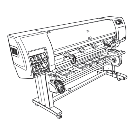
1. Printer engine / Moteur
d'impression / Druckwerk / Motore
della stampante / Sistema de
impresora / Mecanismo de
impressora / Printerengine
2. Stand / Support / Standfuß/
Piedistallo / Soporte / Base /
Standaard
3. Take-up Reel / Enrouleur /
Aufwickelvorrichtung /
Rullo di tensione / Rodillo de
recogida / Rolo de recolhimento /
Opwikkelspoel
4. Spare box / Carton des pièces
détachées / Zubehörkarton /
Scatola dei ricambi / Caja de
repuestos / Caixa sobressalente /
Doos met reserveonderdelen
5. Supplies / Fournitures /
Verbrauchsmaterialkarton /
Materiali di consumo / Suministros /
Suprimentos / Benodigdheden
Please read these instructions carefully. These assembly instructions explain how to assemble the printer. Notice that
EN
the icons used in this document are also located on the printer packaging. The icons help you locate the parts needed
at each stage of the assembly. Because spare screws are supplied, some screws will remain unused after assembly of
the printer.
Veuillez lire attentivement ces instructions. Ces instructions d'assemblage expliquent comment assem-
FR
bler l'imprimante. Notez que les icônes utilisées dans ce document apparaissent également sur l'emballage de
l'imprimante. Les icônes vous aident à localiser les pièces requises à chaque étape de l'assemblage. Des vis de rechange
étant fournies, certaines vis pourront rester inutilisées après l'assemblage de l'imprimante.
Lesen Sie diese Anleitung sorgfältig durch. Dieses Dokument enthält Anleitungen für den Zusammenbau des
DE
Druckers. Die im Dokument verwendeten Symbole befinden sich auch auf der Verpackung des Druckers. Die Symbole
erleichtern das Auffinden der Komponenten, die in den einzelnen Montagephasen benötigt werden. Zum Lieferumfang
gehören Ersatzschrauben, sodass nach dem Zusammenbau einige Schrauben übrig bleiben.
LLeggere attentamente queste istruzioni. Queste istruzioni descrivono le procedure per l'installazione della stam-
IT
pante. Le icone utilizzate in questo documento sono disponibili anche sulla confezione della stampante. Le icone
consentono di individuare le parti necessarie durante i vari passaggi dell'installazione. Poiché vengono fornite viti di
riserva, alcune viti potrebbero risultare inutilizzate dopo l'installazione della stampante.
Lea atentamente estas instrucciones. Estas instrucciones de montaje explican cómo se monta la impresora. Observe
ES
que los iconos utilizados en este documento también se encuentran en el embalaje de la impresora. Los iconos le
ayudan a localizar las piezas necesarias en cada etapa del montaje. Como también se incluyen tornillos de repuesto,
después de montar la impresora quedarán algunos sin utilizar.
Leia essas instruções com atenção. Essas instruções de montagem explicam como montar a impressora. Observe que
PT
os ícones usados neste documento também estão localizados na embalagem da impressora. Os ícones lhe ajudam a
localizar partes necessárias para cada etapa da montagem. Como são fornecidos parafusos sobressalentes, alguns
permanecerão sem uso depois da montagem da impressora.
Lees deze instructies aandachtig door. In deze assemblage-instructies wordt beschreven hoe de printer wordt gemon-
teerd. De pictogrammen die in dit document worden gebruikt, worden ook aangegeven op de verpakking van de printer.
De pictogrammen helpen u de onderdelen te vinden die nodig zijn voor elke fase van de montage. Omdat er reserve-
schroeven zijn geleverd, blijven er na assemblage van de printer enkele ongebruikte schroeven over.
The space required for assembly is 3m
EN
1m
1m
(10 feet) in front and 1m (3.5 feet) at the
3.5ft
3.5ft
sides and rear.
L'espace requis pour l'assemblage est
FR
de 3 m (10 pieds) à l'avant et 1 m (3,5
3m
pieds) sur les côtés et à l'arrière.
10ft
Für die Montage ist vor dem Drucker
DE
ein Freiraum von 3 m, an den Seiten und hinter dem Drucker ein
Freiraum von 1 m erforderlich.
Di seguito è indicato lo spazio necessario per l'installazione: 3 m
IT
davanti e 1 m sui lati e sul retro.
El espacio necesario para el montaje es de 3 m (10 pies) por
ES
la parte frontal y de 1 m (3,5 pies) por los laterales y la parte
trasera.
O espaço necessário para a montagem é de 3 m (10 pés) na
PT
frente e 1 m (3,5 pés) nas laterais e na parte traseira.
De voor de assemblage vereiste ruimte is 3 m aan de voorkant en
1 m aan de zij- en achterkant.
4 people are required to perform certain tasks
EN
L'exécution de certaines tâches nécessite la
FR
présence de 4 personnes.
Für bestimmte Tätigkeiten werden 4 Personen benötigt.
DE
IT
Per determinate operazioni, sono necessarie 4 persone.
Algunas tareas se deben realizar entre 4 personas.
ES
São necessárias quatro pessoas para realizar determinadas
PT
tarefas.
Bepaalde taken moeten door vier personen worden uitgevoerd
Time required for assembly of the printer is approxi-
EN
mately 160 minutes.
2.5h
Le temps nécessaire pour l'assemblage de
FR
l'imprimante est d'environ 160 minutes.
Der Zusammenbau des Druckers dauert ca. 160 Minuten.
DE
Il tempo necessario per l'installazione della stampante è di circa
IT
160 minuti.
El tiempo de montaje de la impresora es de 160 minutos, aproxi-
ES
madamente.
O tempo necessário para a montagem da impressora é de
PT
aproximadamente 160 minutos.
De vereiste tijd voor assemblage van de printer is ongeveer 160
minuten.
1

Verwandte Anleitungen für HP DESIGNJET Z6600


Inhaltszusammenfassung für HP DESIGNJET Z6600
- Seite 1 1. Printer engine / Moteur d’impression / Druckwerk / Motore The space required for assembly is 3m HP DESIGNJET Z6600 della stampante / Sistema de (10 feet) in front and 1m (3.5 feet) at the 3.5ft impresora / Mecanismo de 3.5ft...
- Seite 2 Remove the packaging Retrait de l’emballage Entfernen der Verpackung Rimozione dalla scatola di imballaggio Extracción del embalaje Remova a embalagem Verwijder het verpakkingsmateriaal 5’ Carefully cut the strap around the boxes. Make sure that Remove the boxes shown. the boxes don’t fall when the strap is cut. Retirez les cartons comme indiqué.
- Seite 3 Assemble the stand Assemblage du support Zusammenbauen des Standfußes Assemblaggio del piedistallo Montaje del soporte Montar o suporte Het onderstel in elkaar zetten 20’ Remove boxes and foam shown. Remove the first tray from the box shown. Lower the left side of the cross-brace onto the box marked L and the right side of the cross-brace onto Retirez les boîtes et la mousse comme illustré.
- Seite 4 Locate the bag of screws and the screwdriver provided. Remove the left leg from the box, and then remove the Lower the left leg onto the left side of the cross-brace. Use four screws on the inside of the left leg to attach Notice that the screwdriver is slightly magnetic.
- Seite 5 Use two screws on the outside of the left leg to attach Lower the right leg onto the right side of the cross- Use four screws on the inside of the right leg to attach Use two screws on the outside of the right leg to attach the left leg to the cross-brace.
- Seite 6 Notice that there is anti-slip material around two of the Place a foot on the left leg. There are pins to help you Use four screws to attach the foot to the left leg. Use four screws to attach the cross-bar to the legs. wheels on the feet.
- Seite 7 Position the other foot on the right leg. There are pins Use four screws to attach the foot to the right leg. Roll the stand assembly into its upright position. Attach the left stand spacer to the top of the left leg. It to help you correctly position the foot.
- Seite 8 Attach the printer engine to the stand Fixation du moteur d’impression au support Aufsetzen des Druckwerks auf den Standfuß Collegare il motore della stampante al piedistallo Montaje del sistema de impresora en el soporte Conecte o mecanismo de impressora à base Bevestig de printerengine aan het onderstel 15’...
- Seite 9 Pull open the protective plastic from the base of the Lift the stand assembly onto the printer engine. The Use one screw to attach the right side of the stand to Use two screws to attach the left side of the stand to printer (1), and then remove the two desiccant bags anti-slip material should face the rear of the printer.
- Seite 10 Gire la impresora de modo que quede sobre la caja de di consumo e le rotelle su cui è presente il materiale posição correta. repuestos y la de consumibles. HP recomienda que esta antiscivolo non toccano il pavimento. Posizionare le scatole contenenti i materiali di consumo tarea la realicen cuatro personas.
- Seite 11 Use the hand holds at the rear of the printer engine Remove the two foam end-packs, and then remove the Remove the anti-slip material from the two rear wheels to carefully lift the printer to its upright position. HP plastic covering from the printer engine. on the stand assembly.
- Seite 12 Identify the four holes on the inside of the right Locate the bag of screws that is included in the Insert two screws into the two front holes. Attach the take-up reel motor to the two screws, leg. The holes are used to attach the take-up take-up reel box.
- Seite 13 Use two screws to attach the rear of the take-up Use the serie plug to connect the take-up reel motor to Identify the three holes on the inside of the left Insert two screws into the two front holes. reel motor to the stand, and then tighten all four the parallel port at the rear of the printer.
- Seite 14 Attach the left side of the take-up reel assembly Use one screw to attach the rear of the left side Use four screws to attach the take-up reel At the back of the printer, place one bar with the label to the two screws, and then pull the take-up reel assembly, and then tighten all three screws.
- Seite 15 At the back of the printer, place the 2nd bar with the IMPORTANT Move the printer to its final location. Once Move the front right wheel so that it faces forward (B), Slide the foot sensor unit onto the right foot, and then label pointing towards the other bar label, putting one the TUR sensor is installed, the wheel is locked.
- Seite 16 Attach the cross-brace sensor unit onto the left side of Connect the sensor cable to the rear of the Use the clips provided to attach the sensor cable Remove the take-up reel loading table from the box. the lower cross-brace. take-up reel motor.
- Seite 17 Attach the take-up reel loading table by inserting Attach the grounding cable to the metal plate installed Carefully lift the central core tube. The central Remove the take-up reel spindle from the core. the left side of the loading table into the left support, earlier where the stand attaches to the printer.
- Seite 18 Loosen the plastic nut on the blue hub. Slide the blue hub onto the spindle. Slide the black hub onto the spindle up to the first mark. Tighten the plastic nut on the black hub. Tighten the plastic nut on the blue hub. Faites glisser le moyeu noir sur la bobine jusqu’au Serrez l’écrou en plastique sur le moyeu noir.
- Seite 19 Unpack more components Déballage des autres composants Auspacken weiterer Komponenten Disimballaggio di altri componenti Desembalaje de otros componentes Retire mais componentes da embalagem Meer componenten uitpakken 5’ Raise the take-up reel deflector to its upright position. Unlock the take-up reel by pushing the spindle lever to Load the take-up reel spindle into the printer by its upper most position.
- Seite 20 Remove the packing tapes marked 1 to 7 from Remove the protective covering from the printer Open the printer window, and then remove the packing Remove the packing tape (1), then remove the packing window and the front panel screen. the exterior of the printer, and the two rear ones, and items 1 to 4 from the interior of the printer.
- Seite 21 Install the ink supplies Installation des cartouches d’encre Einsetzen der Tintenpatronen Installazione delle cartucce di inchiostro Instalación de los suministros de tinta Instale os suprimentos de tinta Plaats de inktmaterialen 40’ Plug the Gigabit Ethernet cable into the Gigabit Ethernet Pass the Gigabit Ethernet cable through the hook at the Plug the power cable into the rear of the printer, and connection.
- Seite 22 1’ Turn the Power switch to the On position at the Wait until this message appears on the front panel (~1 Select your region and press OK to continue. If the power light on the front panel remains off, press the Power button to switch on the printer.
- Seite 23 Your region appears highlighted on the map for A message appears to inform you about supported ink Wait until this message appears. The front panel To release the ink cartridge drawer, gently pull down confirmation. Press OK to continue. cartridges. Check the Users Guide for more information guides you through the procedures for inserting the ink on the blue handle, and then slide out the ink cartridge about Ordering Supplies.
- Seite 24 Push the ink cartridge drawer back into the printer until The printer “beeps” when the cartridge is correctly Shake the ink cartridge vigorously for about 15 Place the ink cartridge in the ink cartridge drawer. The the drawer locks into position. seconds.
- Seite 25 Follow the same instructions to insert the other seven Open the printer window, and then remove the packing Remove the packing tape that is holding down the Pull up and release the blue latch on top of the carriage ink cartridges. foam from the top of the printhead carriage.
- Seite 26 Remove the big yellow label that covers the setup Open the window. When the above question on the front panel of your Open window and printhead cover to access printheads. purgers. Ensure Setup purgers are installed. Close printer, you must follow steps 94 to 95 in order to Look at each setup purger and verify that each setup printhead cover and window.
- Seite 27 2’ Wait until this message appears on the front panel. Pull open the maintenance cartridge door, which is Lower the blue latch to close the printhead cover. Select: located on the right side of the printer. Pull down to lock the blue latch on top of the carriage P All with some ink Patientez jusqu’à...
- Seite 28 1’ Remove the two protective covers on the new Remove the transparent shipping tray. Wait until this message appears on the front panel Remove all the setup purgers. printhead. Insert the maintenance cartridge, pushing it in and (about 1 minute). down until it clicks into place, and then close the Retirez toutes les purgeurs de configuration.
- Seite 29 Als een bericht ‘Reseat’ (Opnieuw plaatsen) op het voorpaneel verschijnt, controleer dan of alle beschermende tape is verwijderd en plaats de printkoppen opnieuw. Als het probleem niet is opgelost, raadpleegt u de informatie op de cd/dvd van de HP Start-Up Kit.
- Seite 30 Close the printer window. Wait until the Ready for paper message appears on the Select the altitude where the printer is located. To select Make sure that the blue latch is correctly engaged, and altitude go to: Menu > Setup> Printing Preferences > front panel.
- Seite 31 Load the paper Chargement du papier Laden von Papier Caricamento della carta Carga del papel Coloque o papel Plaats het papier 25’ Unlock and remove the blue hub from the left end of Lift the spindle lock lever. Remove the spindle from the printer. the spindle.
- Seite 32 Slide the blue hub onto the spindle. Make sure that the Make sure that the black hub on the right side of the The right hub of the spindle has two positions: one for Place a roll of paper in the middle of the take up reel blue hub is fully inserted into the roll of paper (no gap spindle is fully inserted into the roll of paper.
- Seite 33 With the blue hub on the left, lift the take-up reel From the front panel, select the paper icon and then Select Load roll and then press the OK button. Insert the lead-edge of the paper into the printer, above deflector to ease the spindle into the printer.
- Seite 34 Macintosh* Windows** Confim the type and length of the paper roll that you On the front panel, select the paper type and paper Please do not try to stop the paper advance; it is The printer automatically aligns the printheads and performs a color calibration for the paper that you loaded loaded into the printer.
- Seite 35 DVD qui se trouve sur le bureau. del DVD sul desktop. * Open the Mac OS X HP Designjet Installer icon and fol- * Wenn die DVD nicht automatisch gestartet wird, öffnen low the instructions on your screen.
- Seite 36 área de trabalho. * Open het Mac OS X HP Designjet Installer-pictogram en * Abra el icono de Mac OS X HP Designjet Installer y siga * Abra o ícone Instalador da HP Designjet para Mac OS X e volg de aanwijzingen op het scherm.