GEA VESTA HWA Originalbetriebsanleitung

Verwandte Anleitungen für GEA VESTA HWA


Inhaltszusammenfassung für GEA VESTA HWA
- Seite 1 Original-Betriebsanleitung/Operating Instructions VESTA Sterilventile/VESTA Sterile Valves Ventilblock HWA/HXA/Valve bloc HWA/HXA Ausgabe/Issue 2014-03 Sach-Nr./Part no. 430-396 Deutsch/English engineering for a better world GEA Mechanical Equipment...
- Seite 2 2014-03 · Ventilblock HWA/HXA / Valve bloc HWA/HXA...
-
Seite 3: Inhaltsverzeichnis
Inhalt Contents Wichtige Abkürzungen und Begriffe ....2 Important Abbreviations and terms ...... 2 Sicherheitshinweise..........4 Safety instructions........... 4 Bestimmungsgemäße Verwendung ....4 Designated use ............ 4 Personal ..............4 Personnel .............. 4 Umbauten, Ersatzteile, Zubehör ......4 Modifications, spare parts, accessories ....4 Allgemeine Vorschriften ........ -
Seite 4: Wichtige Abkürzungen Und Begriffe
Wichtige Abkürzun - Important Abbrevia- gen und Begriffe tions and Terms Britischer Standard British standard Maßeinheit für den Druck Unit of measure for pressure Alle Druckangaben [bar/psi] stehen für All pressure ratings [bar/psi] stand for Überdruck [bar g /psi g ] soweit dies nicht over pressure [bar g /psi g ] if this is not explicitly explizit anders beschrieben ist. - Seite 5 Kv-Wert Durchflusskoeffizient m³/s Cv-Wert flow coefficient US gallons per minute 1 KV = 0,86 x Cv 1 Cv = 1,17 x Kv Maßeinheit für das Volumen Unit of measure for volume Liter litre max. maximal max. maximum Maßeinheit für die Länge Unit of measure for length Millimeter millimetre...
-
Seite 6: Sicherheitshinweise
Sicherheitshinweise Safety Instructions Bestimmungsgemäße Designated use Verwendung Der Ventilblock ist nur für den beschriebenen Verwen- The valve bloc is designed exclusively for the purposes dungszweck bestimmt. Jeder darüber hinausgehende de-scribed below. Using the valve for purposes other Gebrauch gilt als nicht bestimmungsgemäß. Für daraus than those mentioned is considered contrary to its resultierende Schäden haftet Tuchenhagen nicht;... -
Seite 7: Kennzeichnung Von Sicherheitshinweisen In Der Betriebsanleitung
Kennzeichnung von Marking of safety Sicherheitshinweisen in instructions in the der Betriebsanleitung operating manual Die speziellen Sicherheitshinweise stehen direkt vor der Special safety instructions are given directly before the jeweiligen Handlungsanweisung. Sie sind hervorgeho- operating instructions. They are marked by the follow- ben durch ein Gefahrensymbol und ein Signalwort. -
Seite 8: Besondere Gefahrenstellen
Besondere Special Gefahren - hazardous stellen spots GEFAHR DANGER Bei Funktionsstörungen In the event of malfuncti- Ventilblock außer Betrieb ons set the valve bloc out nehmen (von der Strom- of operation (disconnect und Luftzufuhr abtren- the valve from the power nen) und gegen Wieder- and the air supply) and verwendung sichern. -
Seite 9: Transport Und Lagerung
The medium should flow into the opening direction of Das Medium sollte vorzugsweise in Öffnungsrichtung the bellows in order to avoid pressure surges when the des Faltenbalgs fließen, damit Druckschläge beim Öff- valve is closed or opened. nen oder Schließen des Ventils vermieden werden. Following control air pressure has not to be exceeded: Folgenden Steuerluftdruck nicht überschreiten: –... -
Seite 10: Transport
Transport Transport GEFAHR DANGER Die Verpackungseinheiten/Ventilblöcke dürfen nur mit For transport of the package units/valve blocs only use dafür geeigneten Hebezeugen und Anschlagmitteln suitable lifting gears and slings. Observe the instruction transportiert werden. Die auf der Verpackung ange- symbols on the package and on the valve. brachten Bildzeichen beachten. -
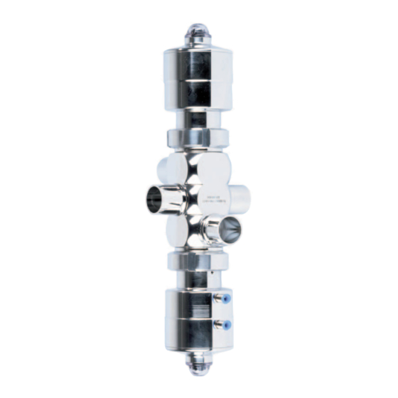
Seite 11: Aufbau Und Funktion
Aufbau und Funktion Design and Function Ventilblock H_A mit Anschlusskopf Ventilblock H_A Ventilblock H_A mit Handantrieb/ Valve bloc H_A with control module Valve bloc H_A Valve bloc H_A with manual actuator 117.1 117.2 B Anschlusskopf T.VIS V-1 / P-1 B Control module T.VIS V-1 / P-1 257 Mechanische 257 Mechnical Position Stellungsanzeige... -
Seite 12: Einbau Und Betrieb
Antrieb NO – federöffnend Antrieb NC – federschließend Actuator NO – spring-to-open Actuator NC – spring-to-close Assembly and Einbau und Operation Betrieb Make sure that Darauf achten, dass – the valve bloc is installed in the pipe system free of –... -
Seite 13: Einbaulage
Einbaulage Installation position Die Einbaulage ist beliebig. The standard installation position of the valve is at the Es muss gewährleistet sein, dass Ventilgehäuse und user´s discrection. Care must be taken that the valve Rohrleitungssystem sicher leerlaufen können. housing and the pipe system can drain properly. Ventil mit lösbaren Valve with detachable Rohranschlußelementen... -
Seite 14: Pneumatischer Anschluss
Pneumatischer Anschluss Pneumatic Connections VORSICHT CAUTION Folgenden Steuerluftdruck nicht überschreiten: The following control air pressure must not be exceeded: – Ventile mit federschließendem Antrieb – max. 8 bar – Valves with spring to-close actuator – max. 8 bar – Ventile mit federöffnendem Antrieb – max. 6 bar –... -
Seite 15: Elektrischer Anschluss
Luftschlauch montieren Installing the air hose Für einen optimalen Sitz im Luftanschluss, ist es To ensure optimum fit in the air connector, the pneu- notwendig, die Pneumatikschläuche mit einem matic hoses must be cut square with a hose cutter. Schlauchschneider rechtwinklig abzuschneiden. •... -
Seite 16: Störung, Ursache, Abhilfe
Störung, Ursache, Malfunction, Cause, Abhilfe Remedy VORSICHT CAUTION Bei Funktionsstörungen Ventilblock sofort abschalten In the event of malfunctions immediately deactivate the und gegen Einschalten sichern. Störungen dürfen nur valve bloc and secure it against inadvertent reactivation. von qualifiziertem Personal unter Beachtung der Sicher- Defects may only be rectified by qualified personnel heitshinweise behoben werden. -
Seite 17: Instandhaltung
Instandhaltung Maintenance Inspektionen Inspections Zwischen den Instandhaltungsintervallen müssen die Between the maintenance intervals, the valve blocs must Dichtheit und die Funktion der Ventilblöcke überwacht be regularly checked for leakage and proper function. werden. • Durch Kontrolle der Leckagebohrung regelmäßig die •... -
Seite 18: Vor Der Demontage
Vor der Demontage Prior to dismantling the valve • Sicherstellen, dass während der Wartungs- und Instandhaltungsarbeiten kein Prozess im entsprechen- • Make sure that during maintenance and repair work den Bereich abläuft. no process is in operation in the area concerned. •... - Seite 19 Mechanische Dismantle Stellungsanzei- mechanical ger demontie- position indica- • Stellungsanzeiger kpl. • Unscrew complete (257) abschrauben. position indicator (257). • O-Ring (256) aus dem • Remove O-ring (256) Deckel (138) entneh- from the cover (138) . men. • Dismount spacer (212) •...
-
Seite 20: Demontage - Montage Des Pneumatischen Antriebs
PTFE-Falten- Separating the balg demontie- PTFE bellows • Remove circlip (253) using external circlip • Sicherungsring (253) pliers. mit einer Außen-Ein- sprengzange entfernen. • Withdraw thrust washer (255) and O-ring (5) • Druckscheibe (255) und from PTFE bellows (15). O-Ring (5) von PTFE- Faltenbalg (15) abzie- hen. -
Seite 21: Demontage Antrieb Ncfederschließend
Demontage Antrieb NC – Dismantling the actuator NC – federschließend spring-to-close • Deckel (138) mit Schrau- • Unscrew cover (138) bendreher (Innensechs- with screwdriver (hex. kant) SW17 abschrau- socket) SW17. ben. • Take O-ring (118) out of • O-Ring (118) aus dem the cover (138). - Seite 22 ✗ ✗ Bei Edelstahlaus- For changing the O-ring führung kann zum (29) on stainless steel Wechseln des O-Ringes actuators, the anti-twist (29) die Verdrehsiche- device must be remo- rung ausgebaut werden. ved. For this purpose Dafür den Stift (251) press the pin (251) to the nach innen drücken, die inside;...
- Seite 23 • Mount the O-rings 226, • O-Ringe 226, 6, 186 6, 186. montieren. • Push the valve stem • Stange (139) von unten (139) from the bottom in die Laterne (9) schie- into the lantern (9). ben. CAUTION VORSICHT Place the center-grooved Der Knebelkerbstift (254) dowel pin (254) into the wird in die Führungsril-...
-
Seite 24: Demontage Antrieb Nofederöffnend
Demontage Dismantle the Antrieb NO – actuator NO – federöffnend spring-to-open • Deckel (138) mit Schrau- • Unscrew cover (138) bendreher (Innensechs- using a screwdriver kant) SW17 abschrau- (hex. socket) SW17. ben. • Dismount O-ring (118). • O-Ring (118) entnehmen entnehmen. - Seite 25 Montage Mounting the Antrieb NO – actuator NO – federöffnend spring-to-open VORSICHT CAUTION Überhöhter Steuerluft- Excess control air may druck kann den Falten- destroy the bellows. balg zerstören. Beim fed- Therefore 6 bar max. of eröffnenden Antrieb (NO) the spring opening max.
- Seite 26 Stellungsanzei- Mount position ger montieren indicator • Distanzstück (217) auf • Screw nut (217) on to die Innensechskant- hex. socket screw (258). schraube (258) schieben. • Screw hex. socket screw • Innensechskantschrau- (258) into the valve be (258) in die Stange stem (139).
-
Seite 27: Demontage - Montage Des Handantriebs
Demontage – Montage Dismantling – Mounting des Handantriebs the manual actuator Demontage Dismantling • Rundstopfen (259) • Remove round plug abnehmen, Sechskant- (259), unscrew hex. nut mutter (217) SW13 (217) SW13 and take out abschrauben, Scheibe washer (212). (212) mit entnehmen. •... -
Seite 28: Wartung
• Handrad (82) auf- • Screw on hand wheel schrauben. (82). • Scheibe (212) auf die • Place washer (212) on to Stange stecken und , the valve stem and Sechskantmutter (217) screw on hex. nut (217) . montieren. • Pin up round plug •... -
Seite 29: Verschleißteile Austauschen
Verschleißteile austauschen Replacing the wearing parts Stets Original-Ersatzteile verwenden. Always use original spare parts. • Defekten Faltenbalg (15) austauschen. • Replace defective bellows (15). • Alle in den Abbildungen gekennzeichneten Dichtun- • Replace all the seals marked in the illustr.: gen austauschen: 6 O-ring 6 O-Ring... -
Seite 30: Verschleißteile / Wearing Parts
Verschleißteile / wearing parts Mit Anschlusskopf T.VIS V-1/P-1 / Mit Handantrieb / With Control module T.VIS V-1/P-1 With manual actuator 2014-03 · Ventilblock HWA/HXA / Valve bloc HWA/HXA... -
Seite 31: Funktion Prüfen
Funktion prüfen Functional test • Ventil mit Druckluft ansteuern. • Actuate the valve by applying compressed air. • Bei abgebautem Anschlusskopf oder bei abgebauter • Check the valve stroke when the control module or transparenter Haube des Anschluss kopfes den Ventil- the transparent cap of the control module are not hub kontrollieren. -
Seite 32: Technische Daten
Technische Daten Technical Data Baugröße DN 10 bis 25 Size DN 10 to 25 1/2 bis 1" OD 1/2 to 1" OD ISO 13,5 bis 33,7 ISO 13.5 to 33.7 Gewicht s. Tabelle im Kapitel Weight see table in Chapt. „Transport und Lagerung“... -
Seite 33: Werkzeug / Schmierstoff
Tools / Lubricant Werkzeug / Schmierstoff Tool Werkzeug Hexagon screwdriver, size 3 mm Sechskantschraubendreher Größe 3 mm (for hexagon socket screw) (für Innensechskantschrauben) Hexagon screwdriver, size 17 mm Sechskantschraubendreher Größe 17 mm (for hexagon socket screw) (für Innensechskantschrauben) Hexagon screwdriver, size 12 mm Sechskantschraubendreher Größe 12 mm (for hexagon socket screw) (für Innensechskantschrauben) - Seite 34 Valve bloc HWA, 3 sockets Pneumatischer Antrieb H_A/M / pneumatic actuation H_A/M Metallausführung / stainless steel 257** **256 212** **258 98 a Ventilblock HXA, 4-stutzig Valve bloc HXA, 4 sockets 98 b *253 *255 GEA Mechanical Equipment GEA Tuchenhagen GmbH...
- Seite 35 Ersatzteilliste / Spare parts list Datum/date: 2012-11-26 Seite / Page 2 von / of 5 VESTA Sterilventile / VESTA Sterile Valves Ventilblock HWA und HXA / valve bloc HWA and HXA 221ELI003913G_1.DOC pneumatischer Antrieb H_A / pneumatic actuation H_A Kunststoffausführung / synthetics 257** Gehäuse HWA / Housing HWA 3-stutzig / 3 sockets...
- Seite 36 Adapter T.VIS/V-1 / adaptor T.VIS/V-1 1.4301 221-002253 221-002253 221-002253 221-002253 O-Ring / O-ring 930-903 930-903 930-903 930-903 O-Ring / O-ring 930-012 930-012 930-012 930-012 GEA Mechanical Equipment GEA Tuchenhagen GmbH I d t i k 2 10 21514 Bü h...
- Seite 37 221-002303 221-002303 221-002304 138.3 Deckel T.VIS/V-1 / cover T.VIS/V-1 1.4305 221-002173 221-002173 221-002174 Adapter T.VIS/V-1 / adaptor T.VIS/V-1 1.4301 221-002253 221-002253 221-002253 O-Ring / O-ring 930-903 930-903 930-903 O-Ring / O-ring 930-012 930-012 930-012 GEA Mechanical Equipment GEA Tuchenhagen GmbH...
- Seite 38 Deckel T.VIS/V-1 / cover T.VIS/V-1 1.4305 221-002173 221-002173 221-002174 221-002174 221-002175 Adapter T.VIS/V-1 / adaptor T.VIS/V-1 1.4301 221-002253 221-002253 221-002253 221-002253 221-002253 O-Ring / O-ring 930-903 930-903 930-903 930-903 930-903 O-Ring / O-ring 930-012 930-012 930-012 930-012 930-012 GEA Mechanical Equipment GEA Tuchenhagen GmbH...
- Seite 44 O-Ring / O-ring HNBR 930-866 Halteblech H_A / holding device H_A 1.4301 221-001769 Schaltring H_A / switch ring H_A 1.4301 221-001774 Schaltstange H_A / switch bar H_A 1.4301 221-001770 Schild, dreieckig / shield, triangular PVC-Folie 700-130 Process Equipment GEA Tuchenhagen GmbH...
- Seite 46 We live our values. Excellence Passion Integrity Responsibility GEA-versity GEA Group is a global engineering company with multi-billion euro sales and operations in more than 50 countries. Founded in 1881, the company is one of the largest providers of innovative equipment and process technology.