Optimum OPTidrill D17Pro Betriebsanleitung

Verwandte Anleitungen für Optimum OPTidrill D17Pro


Inhaltszusammenfassung für Optimum OPTidrill D17Pro
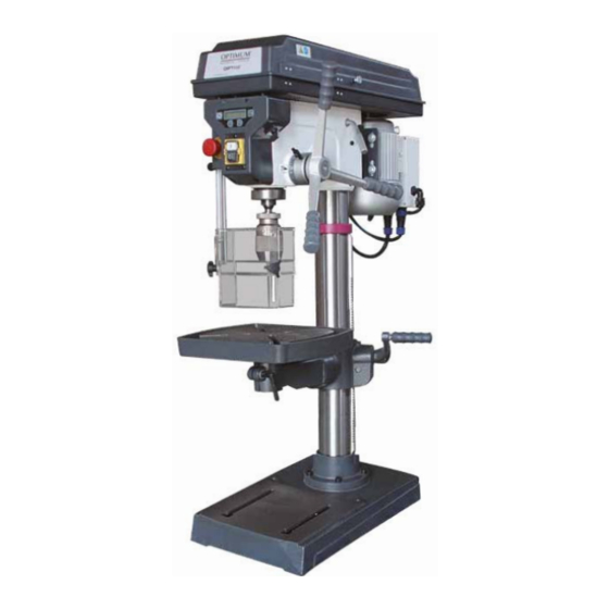
- Seite 1 Betriebsanleitung - DE Operating Manual - EN Version 1.0.3 Bohrmaschine Drilling machine Artikel Nr. Part no. 3003010 Artikel Nr. Part no. 3003015 3003020 Artikel Nr. Part no. 3003030 30030302 Artikel Nr. Part no. 3003040 D23 Pro - 400V (D17 Pro - is similar) D26 Pro D33 Pro...
-
Seite 2: Inhaltsverzeichnis
Sicherheit Typschilder ..............................7 Sicherheitshinweise (Warnhinweise) ......................8 1.2.1 Gefahren-Klassifizierung........................8 1.2.2 Weitere Piktogramme........................9 Bestimmungsgemäße Verwendung......................10 Vernünftigerweise vorhersehbare Fehlanwendung ..................10 1.4.1 Vermeidung von Fehlanwendungen ....................10 Gefahren, die von der Bohrmaschine ausgehen ..................11 Qualifikation ..............................12 1.6.1 Private Nutzer .......................... - Seite 3 Drehzahlveränderung ...........................39 4.7.1 Drehzahltabellen..........................39 4.7.2 Drehzahlanzeige..........................42 Vor dem Arbeitsgang............................42 Während dem Arbeitsgang...........................42 4.10 Pinolenvorschub............................42 4.11 Ausbau, Einbau von Bohrfuttern und Bohrern....................43 4.12 Schnellspann - Bohrfutter ..........................43 4.12.1 Einbau Bohrfutter..........................43 4.13 Kühlung ................................44 Ermitteln der Schnittgeschwindigkeit und der Drehzahl Tabelle Schnittgeschwindigkeiten/ Vorschub ....................45 Drehzahltabelle ............................45 5.2.1 Beispiel zur rechnerischen Ermittlung der erforderlichen Drehzahl an Ihrer Bohrmaschine ..47...
- Seite 4 1.15 Safety during operation..........................70 1.16 Safety during maintenance .......................... 71 1.16.1 Disconnecting and securing the drilling machine ................71 1.17 Using lifting equipment ..........................71 1.17.1 Mechanical maintenance ....................... 71 1.18 Accident report............................. 71 1.19 Electronics ..............................71 1.20 Inspection deadlines ............................
- Seite 5 6.3.1 Customer service technician......................107 Malfunctions Appendix Copyright ..............................109 Terminology/Glossary ..........................109 Liability claims/warranty ..........................109 Storage...............................110 Advice for disposal / Options of reuse: .......................110 8.5.1 Decommissioning .........................111 8.5.2 Disposal of new device packaging....................111 8.5.3 Disposal of the old device......................111 8.5.4 Disposal of electrical and electronic components .................111 Disposal via municipal collection facilities ....................112 8.6.1 Change information operating manual..................112...
- Seite 6 Sehr geehrter Kunde, vielen Dank für den Kauf eines Produktes von OPTIMUM. OPTIMUM Metallbearbeitungsmaschinen bieten ein Höchstmaß an Qualität, technisch optimale Lösungen und überzeugen durch ein herausragendes Preis-Leistungs-Verhältnis. Ständige Weiterentwicklungen und Produktinnovationen gewähren jederzeit einen aktuellen Stand an Technik und Sicherheit.
-
Seite 7: Sicherheit
Sicherheit Konventionen der Darstellung gibt zusätzliche Hinweise fordert Sie zum Handeln auf Aufzählungen Dieser Teil der Betriebsanleitung erklärt Ihnen die Bedeutung und die Verwendung der in dieser Betriebsanleitung verwende- ten Warnhinweise, legt die bestimmungsgemäße Verwendung der Bohrmaschine fest, ... -
Seite 8: Sicherheitshinweise (Warnhinweise)
INFORMAT ION Können Sie Probleme nicht mit Hilfe dieser Betriebsanleitung lösen, fragen Sie an bei: Optimum Maschinen Germany GmbH Dr. Robert-Pfleger-Str. 26 D-96103 Hallstadt E-Mail: info@optimum-maschinen.de Sicherheitshinweise (Warnhinweise) 1.2.1 Gefahren-Klassifizierung Wir teilen die Sicherheitshinweise in verschiedene Stufen ein. Die untenstehende Tabelle gibt Ihnen eine Übersicht über die Zuordnung von Symbolen (Piktogrammen) und Signalwörtern zu... -
Seite 9: Weitere Piktogramme
Wir ersetzen bei konkreten Gefahren das Piktogramm oder allgemeine Gefahr durch eine Handverletzungen, gefährlicher Einzugsgefahr. Warnung vor elektrischer Spannung, 1.2.2 Weitere Piktogramme Warnung Rutschgefahr! Warnung Stolpergefahr! Warnung heiße Oberfläche! Warnung biologische Gefährdung! Warnung vor Warnung Kippgefahr! Warnung schwebende Vorsicht, Gefahr durch automatischem Anlauf! Lasten! explosionsgefährliche... -
Seite 10: Bestimmungsgemäße Verwendung
Wir übernehmen keine Haftung für Schäden aufgrund einer nicht bestimmungsgemäßen Ver- wendung. Wir weisen ausdrücklich darauf hin, dass durch nicht von der Firma Optimum Maschinen Ger- many GmbH genehmigte konstruktive, technische oder verfahrenstechnische Änderungen auch die Garantie erlischt. -
Seite 11: Gefahren, Die Von Der Bohrmaschine Ausgehen
WARNUNG! Verletzung durch wegschleudernde Werkstücke. Spannen Sie das Werkstück in den Maschinenschraubstock. Vergewissern Sie sich, dass das Werkstück fest in dem Maschinenschraubstock bzw. der Maschinenschraubstock fest auf den Maschinentisch gespannt ist. Einsatz von Kühl- und Schmiermittel zur Steigerung der Standzeit am Werkzeug und Ver- besserung der Oberflächenqualität. -
Seite 12: Qualifikation
WARNUNG! Die Bohrmaschine darf nur mit funktionierenden Sicherheitseinrichtungen betrieben werden. Schalten Sie die Bohrmaschine sofort ab, wenn Sie feststellen, dass eine Sicherheitseinrichtung fehlerhaft oder demontiert ist! Alle betreiberseitigen Zusatzanlagen müssen vorgeschriebenen Sicherheitseinrichtungen ausgerüstet sein. Sie als Betreiber sind dafür verantwortlich! ... -
Seite 13: Bedienerpositionen
Fachpersonal Fachpersonal ist aufgrund seiner fachlichen Ausbildung, Kenntnisse und Erfahrung sowie Kenntnis der einschlägigen Bestimmungen in der Lage, die ihm übertragenen Arbeiten auszu- führen und mögliche Gefahren selbstständig zu erkennen und zu vermeiden. Unterwiesene Person Die unterwiesene Person wurde in einer Unterweisung durch den Betreiber über die ihr übertra- genen Aufgaben und möglichen Gefahren bei unsachgemäßem Verhalten unterrichtet. -
Seite 14: Sicherheitsüberprüfung
WARNUNG! Wenn Sie eine Sicherheitseinrichtung überbrücken, entfernen oder auf andere Art außer Funktion setzen, gefährden Sie sich und andere an der Bohrmaschine arbeitende Menschen. Mögliche Folgen sind Verletzungen durch weggeschleuderte Werkstücke oder Werkstückteile, das Berühren von rotierenden Teilen, ein tödlicher Stromschlag, ... -
Seite 15: Not-Halt Schalter
Funktionsprüfung Einrichtung Prüfung Not-Halt Schalter Nach dem Betätigen des Not-Halt Schalter muss die Bohrmaschine abschalten. Bohrfutterschutz Die Bohrmaschine darf erst einschalten, wenn der Bohrfutterschutz geschlossen ist. Der Bohrfutterschutz muss beim Öffnen während des Betriebs den Motor abschalten. Schutzabdeckung Die Bohrmaschine darf erst einschalten, wenn die Keilriemen Schutzabdeckung der Keilriemen geschlossen ist. -
Seite 16: Körperschutzmittel
1.14 Körperschutzmittel Bei bestimmten Arbeiten benötigen Sie Körperschutzmittel als Schutzausrüstung. Diese sind: Schutzhelm, Schutzbrille oder Gesichtsschutz, Schutzhandschuhe, Sicherheitsschuhe mit Stahlkappen, Gehörschutz. Überzeugen Sie sich vor Arbeitsbeginn davon, dass die vorgeschriebene Ausrüstung am Arbeitsplatz verfügbar ist. VORSICHT! Verunreinigte, unter Umständen kontaminierte Körperschutzmittel können Erkrankungen auslösen. -
Seite 17: Sicherheit Bei Der Instandhaltung
Überprüfen Sie nach dem Wiedereinbau deren Funktion! 1.18 Unfallbericht Informieren Sie Vorgesetzte und die Firma Optimum Maschinen Germany GmbH sofort über Unfälle, mögliche Gefahrenquellen und „Beinahe“-Unfälle. „Beinahe“-Unfälle können viele Ursachen haben. Je schneller sie berichtet werden, desto schneller können die Ursachen behoben werden. -
Seite 18: Prüffristen
vor der ersten Inbetriebnahme und nach einer Änderung oder Instandsetzung vor der Wie- derinbetriebnahme durch eine Elektrofachkraft oder unter Leitung und Aufsicht einer Elekt- rofachkraft und in bestimmten Zeitabständen. Die Fristen sind so zu bemessen, dass entstehende Mängel, mit denen gerechnet werden muss, rechtzeitig festgestellt werden. -
Seite 19: Technische Daten
Technische Daten Die folgenden Daten sind Maß- und Gewichtsangaben und die vom Hersteller genehmigten Maschinendaten. Die kalkulierte vorgesehene Lebensdauer der Maschine nach EN ISO 13849 und EN ISO 12100 beträgt mindestens 10 Jahre bei einem täglichen Betrieb von 8h an 220 Arbeitstagen pro Jahr bei Einhaltung der Umgebungsbedingungen, der bestimmungsgemäßen Verwendung und der Einhaltung von erforderlichen Wartungsintervallen. -
Seite 20: Emissionen
D17 Pro D23 Pro D26 Pro D33 Pro Abstand Spindel - Tisch (max.) max. 325 mm max. 425 mm max. 720 mm max. 695 mm maximaler Abstand [mm] max. 530 mm max. 618 mm max. 1230 mm max. 1180 mm Spindel - Fuß... -
Seite 21: Abmessungen
Außerdem können die zulässigen Belastungspegel aufgrund nationaler Bestimmungen von Land zu Land unterschiedlich sein. Diese Information über die Lärmemission soll es aber dem Betreiber der Maschine erlauben, eine bessere Bewertung der Gefährdung und der Risiken vorzunehmen. Abmessungen 2.2.1 D17 Pro Schwerpunkt / Centre of gravity Technische Daten D17 Pro│D23 Pro│D26 Pro│D33 Pro... -
Seite 22: D23 Pro
2.2.2 D23 Pro Schwerpunkt / Centre of gravity Technische Daten D17 Pro│D23 Pro│D26 Pro│D33 Pro Originalbetriebsanleitung Version 1.0.3 - 2020-07-14... -
Seite 23: D26 Pro
2.2.3 D26 Pro Schwerpunkt / Centre of gravity Technische Daten D17 Pro│D23 Pro│D26 Pro│D33 Pro Version 1.0.3 - 2020-07-14 Originalbetriebsanleitung... -
Seite 24: D33 Pro
2.2.4 D33 Pro Schwerpunkt / Centre of gravity Technische Daten D17 Pro│D23 Pro│D26 Pro│D33 Pro Originalbetriebsanleitung Version 1.0.3 - 2020-07-14... - Seite 25 Technische Daten D17 Pro│D23 Pro│D26 Pro│D33 Pro Version 1.0.3 - 2020-07-14 Originalbetriebsanleitung...
-
Seite 26: Anlieferung, Innerbetrieblicher Transport, Montage Und Inbetriebnahme
Anlieferung, Innerbetrieblicher Transport, Montage und Inbetriebnahme Hinweise zu Transport, Aufstellung, Inbetriebnahme Unsachgemäßes Transportieren, Aufstellen und Inbetriebnehmen ist unfallträchtig und kann Schäden oder Funktionsstörungen an der Maschine verursachen, für die wir keine Haftung bzw. Garantie gewähren. Lieferumfang gegen Verschieben oder Kippen gesichert mit ausreichend dimensioniertem Flur- förderfahrzeug oder einem Kran zum Aufstellort transportieren. -
Seite 27: Anlieferung
Anlieferung INFORMATION Die Bohrmaschine ist verpackungsgerecht zerlegt. Vor der Inbetriebnahme muss die Bohrma- schine zusammengebaut werden. Die Anlieferung erfolgt in einer Transportkiste. Nach dem Auspacken und dem Transport an den Aufstellort müssen einzelne Komponenten der Maschine montiert und zusammengefügt werden. Kontrollieren Sie unverzüglich nach Erhalt der Maschine den Zustand und reklamieren Sie sofort eventuelle Schäden beim letzten Transportführer, auch dann, wenn die Verpackung nicht beschädigt ist. -
Seite 28: Montieren Von Standfuß Und Bohrsäule
Montieren von Standfuß und Bohrsäule Stellen Sie den Standfuß auf den Schraube Boden und befestigen Sie die Bohr- säule mit dem Standfuß. Am Standfuß sind Befestigungsschrauben für die Haltering Bohrsäule vorgesehen. Zahnstange Lösen Sie die Schraube am Haltering und entfernen Sie den Haltering und Bohrsäule die Zahnstange. - Seite 29 Setzen Sie den Bohrtisch in den Bohr- tischträger ein, und klemmen sie ihn mit dem Klemmhebel fest. Bohrtisch Klemmhebel Abb. 3-4: D26Pro Montage des Schnellspann - Bohrfutters Vor dem Arbeitsgang auf Seite 42 Montage des Bohrfutterschutzes WARNUNG! Halterung Bohrmaschinen dürfen nicht ohne Bohrfut- terschutz betrieben werden.
- Seite 30 4. Achten Sie darauf, dass die Einstell- schraube nach erfolgter Montage und im geschlossenen Zustand des Bohr- futterschutzes nach vorne zeigt. Einstellschraube Abb. 3-7: Montage-3 INFORMATION In der Halterung des Bohrfutterschutzes ist ein Schalter integriert, der die geschlossene Stel- lung überwacht. Solange der Bohrfutterschutz nicht geschlossen ist, lässt sich die Maschine nicht starten.
-
Seite 31: Aufstellbedingungen
Aufstellbedingungen Gestalten Sie den Arbeitsraum um die Maschine entsprechend der örtlichen Sicherheits-Vor- schriften. Der Arbeitsraum für die Bedienung, Wartung und Instandsetzung darf nicht einge- schränkt werden. Die Beleuchtung des Arbeitsplatzes ist so zu gestalten, dass an der Werkzeugspitze eine Beleuchtungsstärke von 500 Lux erreicht wird. Falls dies mit der herkömmlichen Ausleuchtung des Aufstellungsorts nicht gewährleistet ist, muss eine optional erhältliche Arbeitsplatzleuchte eingesetzt werden. - Seite 32 D17 Pro Abb. 3-8: Befestigung Fuß D17 Pro D23 Pro Abb. 3-9: Befestigung Fuß D23 Pro D17 Pro│D23 Pro│D26 Pro│D33 Pro Originalbetriebsanleitung Version 1.0.3 - 2020-07-14...
- Seite 33 D26 Pro Abb. 3-10: Befestigung Fuß D26Pro D33 Pro Abb. 3-11: Befestigung Fuß D33 Pro D17 Pro│D23 Pro│D26 Pro│D33 Pro Version 1.0.3 - 2020-07-14 Originalbetriebsanleitung...
-
Seite 34: Erste Inbetriebnahme
Maschine ausgeliefert wurden oder als optionale Ausrüstungen von OPTIMUM angeboten werden. Verwenden Sie Werkzeugaufnahmen nur in dem dafür vorgesehenen, zulässigen Dreh- zahlbereich. Werkzeugaufnahmen dürfen nur in Übereinstimmung mit den Empfehlungen von OPTIMUM oder des Spannzeug-Herstellers verändert werden. WARNUNG! Bei der ersten Inbetriebnahme der Bohrmaschine durch unerfahrenes Personal gefährden Sie Menschen und die Ausrüstung. -
Seite 35: Warmlaufen Der Maschine
3.7.1 Warmlaufen der Maschine ACHTUNG! Wird die Bohrmaschine, insbesondere die Bohrspindel, im ausgekühlten Zustand sofort auf Maximalleistung betrieben, kann es dazu führen, dass diese beschädigt wird. Eine ausgekühlte Maschine, wie es beispielsweise direkt nach dem Transport vorkommen kann, sollte deshalb die ersten 30 Minuten lediglich bei einer Spindelgeschwindigkeit von etwa 500 1/min warmgefahren werden. -
Seite 36: Bedienung
Bedienung Bedien- und Anzeigeelemente Abb. 4-1: D23 Pro - Bedien- und Anzeigeelemente Pos. Bezeichnung Pos. Bezeichnung Drucktaster "Aus" Drucktaster "Ein" Drehrichtungsschalter NOT-Halt Schalter (nur an 400V Maschinen) Klemmhebel Skala Bohrtiefenanschlag Schnellspannbohrfutter Schutzabdeckung Keilriemengehäuse Griff für Keilriemenspannung Hebel für Pinolenvorschub Bohrtisch Tischhöhenverstellung Digitale Anzeige... -
Seite 37: Bedienfeld
Bedienfeld Drucktaster EIN Der „Drucktaster EIN“ schaltet die Drehung der Bohrspindel ein. Drucktaster Aus Der „Drucktaster AUS“ schaltet die Drehung der Bohrspindel aus. Drehrichtungsschalter an D23 Pro - 400V an D26 Pro an D33 Pro Maschine einschalten INFORMATION Solange der Bohrfutterschutz nicht geschlossen ist, lässt sich die Maschine nicht starten. -
Seite 38: Digitale Bohrtiefe
4.5.2 Digitale Bohrtiefe Zeigt die aktuelle Bohrtiefe an. Nullpunkt Bohrtiefe Display Ein / Aus Umschaltung auf Drehzahlanzeige Einheit Metrisch / Zoll Abb. 4-3: Digitale Anzeige Tischneigung VORSICHT! Je weiter der Bohrtisch nach links oder rechts geneigt wird, desto geringer ist die Tragfähigkeit und die Klemmwirkung des geneigten Bohrtisches. -
Seite 39: Drehzahlveränderung
Drehzahlveränderung VORSICHT! Vorbeugende Sicherheitsmaßnahme. Ziehen Sie den Netzstecker der Bohrmaschine. Die Maschine von der elektrischen Schutzabdeckung Versorgung trennen. Keilriemen Die Verschraubung an der Schutzab- deckung der Keilriemen lösen. Gleitschienen- schrauben Griff Abb. 4-5: Riemenantrieb Öffnen Sie die Schutzabdeckung. ... - Seite 40 D23 Pro 50Hz Bedienung D17 Pro│D23 Pro│D26 Pro│D33 Pro Originalbetriebsanleitung Version 1.0.3 - 2020-07-14...
- Seite 41 D26 Pro 50Hz D33 Pro 50Hz Bedienung D17 Pro│D23 Pro│D26 Pro│D33 Pro Version 1.0.3 - 2020-07-14 Originalbetriebsanleitung...
-
Seite 42: Drehzahlanzeige
4.7.2 Drehzahlanzeige Zeigt die aktuelle Drehzahl an. Nullpunkt Bohrtiefe Display Ein / Aus Umschaltung auf Drehzahlanzeige Einheit Metrisch / Zoll Abb. 4-6: Digitale Anzeige Vor dem Arbeitsgang WARNUNG! Bei Bohrarbeiten muss das Werkstück sicher gespannt sein um es gegen Mitnahme durch Bohrer sichern. -
Seite 43: Ausbau, Einbau Von Bohrfuttern Und Bohrern
4.11 Ausbau, Einbau von Bohrfuttern und Bohrern VORSICHT! Vorbeugende Sicherheitsmaßnahme. Ziehen Sie den Netzstecker der Bohrmaschine. ACHTUNG! Das Werkzeug und/oder das Bohrfutter fällt nach unten. Halten Sie während des Austrei- bens das Werkzeug oder das Bohrfutter fest. Kegeldorne lassen sich mit einem gewöhnlichen Austreiber ausbauen. ... -
Seite 44: Kühlung
Prüfen bzw. Reinigen sie den konischen Sitz in der Bohrspindel und am Kegeldorn des Werkzeugs oder des Bohrfutters. Drücken Sie den Kegeldorn in die Bohrspindel. 4.13 Kühlung Durch die Drehbewegung entstehen an der Werkzeugschneide hohe Temperaturen durch die auftretende Reibungswärme. -
Seite 45: Ermitteln Der Schnittgeschwindigkeit Und Der Drehzahl
Ermitteln der Schnittgeschwindigkeit und der Drehzahl Tabelle Schnittgeschwindigkeiten/ Vorschub Werkstofftabelle empfohlener Vorschub f empfohlene in mm/Umdrehung Schnitt- zu bearbeitender geschwindigkeit Werkstoff Bohrerdurchmesser d in mm Vc in m/min 2...3 >3...6 >6...12 >12...25 >25...50 unlegierte Baustähle 30 - 35 0,05 0,10 0,15 0,25 0,35... - Seite 46 in m/min Bohrer Ø Drehzahl in U/min in mm 1146 1274 1592 1911 2229 2548 3185 3822 5096 6369 1042 1158 1448 1737 2027 2316 2895 3474 4632 5790 1062 1327 1592 1858 2123 2654 3185 4246 5308 1225 1470 1715 1960 2450...
-
Seite 47: Beispiel Zur Rechnerischen Ermittlung Der Erforderlichen Drehzahl An Ihrer Bohrmaschine
in m/min Bohrer Ø Drehzahl in U/min in mm 41,0 42,0 43,0 44,0 45,0 46,0 47,0 48,0 49,0 50,0 5.2.1 Beispiel zur rechnerischen Ermittlung der erforderlichen Drehzahl an Ihrer Bohrma- schine Die notwendige Drehzahl hängt vom Durchmesser des Bohrers, des zu bearbeitenden Werk- stoffs, sowie vom Schneidwerkstoff des Bohrers ab. -
Seite 48: Instandhaltung
Instandhaltung Im diesem Kapitel finden Sie wichtige Informationen zu Inspektion, Wartung, Instandsetzung. ACHTUNG! Die regelmäßige, sachgemäß ausgeführte Instandhaltung ist eine wesentliche Voraussetzung für die Betriebssicherheit, einen störungsfreien Betrieb, eine lange Lebensdauer der Maschine und die Qualität der von Ihnen hergestellten Produkte. -
Seite 49: Wiederinbetriebnahme
6.1.2 Wiederinbetriebnahme Führen Sie vor der Wiederinbetriebnahme eine Sicherheitsüberprüfung durch. Sicherheitsüberprüfung auf Seite 14 WARNUNG! Überzeugen Sie sich vor dem Starten der Maschine unbedingt davon, dass dadurch keine Gefahr für Personen entsteht, die Maschine nicht beschädigt wird. Inspektion und Wartung Die Art und der Grad des Verschleißes hängt in hohem Maße von den individuellen Einsatz- und Betriebsbedingungen ab. - Seite 50 Intervall Was? Wie? Ölen Sie die Bohrsäule regelmäßig mit handelsüblichen Öl ein. Schmieren Sie die Zahnstange regelmäßig mit handelsübli- chen Fett (z.B. Gleitlagerfett) ein. Bohrsäule Monatlich Zahnstange Prüfen Sie die Keilriemen im Bohrkopf auf Porosität und Ver- schleiß.
- Seite 51 Intervall Was? Wie? VORSICHT! Teile können Ihnen entgegenfliegen. Demontage des Federgehäuses ist darauf zu achten, dass nur qualifiziertes Personal die Maschine wartet und instand setzt. Lösen Sie die beiden Muttern ca. 1/4 Umdrehung entgegen dem Uhrzeigersinn am Federgehäuse. Entfernen Sie unter kei- nen Umständen die Muttern komplett vom Gewinde! ...
- Seite 52 Intervall Was? Wie? Eine Entstehung von ungewöhnlichen Klappergeräuschen kann durch Nachfetten beseitigt werden. Die Pinole (1) bewegt sich beim Bohrvorschub mit der verzahnten Spindel (2) in der fest stehenden angetriebenen Hülse (3) nach unten oder nach oben. Die Geräusche entstehen durch das notwendige Spiel der beiden Verzahnungen Hülse Spindel.
-
Seite 53: Instandsetzung
Führt Ihr qualifiziertes Fachpersonal die Reparaturen durch, so muss es die Hinweise dieser Betriebsanleitung beachten. Die Firma Optimum Maschinen Germany GmbH übernimmt keine Haftung und Garantie für Schäden und Betriebsstörungen als Folge der Nichtbeachtung dieser Betriebsanleitung. Verwenden Sie für die Reparaturen nur einwandfreies und geeignetes Werkzeug, ... -
Seite 54: Störungen
Störungen Ursache/ Störung Abhilfe mögliche Auswirkungen Motor wird heiß • Falscher elektrischer Anschluss an • 400 V-Maschinen Geräusche beim Arbeiten. • Spindel läuft trocken. • Spindel schmieren. • Werkzeug ist stumpf oder falsch • Neues Werkzeug verwenden und gespannt. Spannung überprüfen (Festsitz des Bohrers, Bohrfutters und Kegel- dorn). -
Seite 55: Anhang
Rahmen einer einzelnen, vertraglichen Regel zugesagt wurden. Die Abwicklung der Haftungs- oder Garantieansprüche erfolgt nach Wahl der Firma OPTIMUM GmbH entweder direkt mit der Firma OPTIMUM GmbH oder aber über einen ihrer Händler. Defekte Produkte oder deren Bestandteile werden entweder repariert oder gegen feh- lerfreie ausgetauscht. -
Seite 56: Lagerung
Keilriemen, Kugellager, Leuchtmittel, Filter, Dichtungen u.s.w. - nicht reproduzierbare Softwarefehler Leistungen, die die Firma OPTIMUM GmbH oder einer ihrer Erfüllungsgehilfen zur Erfüllung im Rahmen einer zusätzlichen Garantie erbringen, sind weder eine Anerkennung eines Mangels noch eine Anerkennung der Eintrittspflicht. Diese Leistungen hemmen und/oder unterbrechen die Garantiezeit nicht. -
Seite 57: Entsorgungshinweis / Wiederverwertungsmöglichkeiten
Fragen Sie bei der Optimum Maschinen Germany GmbH an, falls die Maschine und Zubehör- teile länger als drei Monate und unter anderen als den vorgeschriebenen Umgebungsbedingun- gen gelagert werden müssen. Entsorgungshinweis / Wiederverwertungsmöglichkeiten: Entsorgen Sie ihr Gerät bitte umweltfreundlich, indem Sie Abfälle nicht in die Umwelt sondern fachgerecht entsorgen. -
Seite 58: 8.5.4 Entsorgung Der Elektrischen Und Elektronischen Komponenten
Veränderte Einstelldaten Erfahrungen mit der Bohrmaschine, die für andere Benutzer wichtig sind Wiederkehrende Störungen Optimum Maschinen Germany GmbH Dr.-Robert-Pfleger-Str. 26 D-96103 Hallstadt Telefax +49 (0) 951 - 96 555 - 888 E-Mail: info@optimum-maschinen.de Anhang D17 Pro│D23 Pro│D26 Pro│D33 Pro Originalbetriebsanleitung Version 1.0.3 - 2020-07-14... -
Seite 59: Eg-Konformitätserklärung
EG - Konformitätserklärung nach Maschinenrichtlinie 2006/42/EG Anhang II 1.A Der Hersteller / Inverkehrbringer: Optimum Maschinen Germany GmbH Dr.-Robert-Pfleger-Str. 26 D - 96103 Hallstadt erklärt hiermit, dass folgendes Produkt Produktbezeichnung: Bohrmaschine Typenbezeichnung: D17 Pro | D23 Pro | D26 Pro | D33 Pro Handelsbezeichnung: OPTIdrill D17 Pro | OPTIdrill D23 Pro... - Seite 60 Dear customer, Thank you very much for purchasing a product made by OPTIMUM. OPTIMUM metal working machines offer a maximum of quality, technically optimum solutions and convince by an outstanding price performance ratio. Continuous enhancements and product innovations guarantee state-of-the-art products and safety at any time.
-
Seite 61: Safety
Safety Glossary of symbols provides further instructions calls on you to act listings This part of the operating instructions explains the meaning and use of the warning notes included in these operating instructions, defines the intended use of the drilling machine, ... -
Seite 62: Safety Instructions (Warning Notes)
INFORMATION If you are unable to rectify an issue using these operating instructions, please contact us for advice: Optimum Maschinen Germany GmbH Dr. Robert-Pfleger-Str. 26 D-96103 Hallstadt, Germany Email: info@optimum-maschinen.de Safety instructions (warning notes) 1.2.1 Classification of hazards We classify the safety warnings into different categories. The table below gives an overview of the classification of symbols (ideogram) and the warning signs for each specific danger and its (possible) consequences. -
Seite 63: Other Pictograms
In case of specific dangers, we replace the pictogram with general danger with a warning of injury to hands, hazardous risk of electrical voltage, entanglement. 1.2.2 Other pictograms Warning: danger of Warning: risk of stumbling! Warning: hot surface! Warning: biological hazard! slipping! Warning: automatic start- Warning: tilting danger! -
Seite 64: Intended Use
If the drilling machine is used in any way other than described above, modified without authori- zation of Optimum Maschinen Germany GmbH, then the drilling machine is being used improp- erly. -
Seite 65: Possible Dangers Caused By The Drilling Machine
WARNING! Risk of injury caused by flying workpieces. Clamp the workpiece in the machine vice. Make sure that the workpiece is firmly clamped in the machine vice and that the machine vice is firmly clamped onto the machine table. Use cooling and lubricating agents to increase the durability of the tool and to improve the surface quality. -
Seite 66: Qualification
All additional devices installed by the operator must be equipped with the stipulated safety devices. This is your responsibility as the operator! Safety devices on page 67 Qualification It is indispensable that the operator is suitably qualified for safe use and secure setting and operation of the machine. -
Seite 67: User Positions
Instructed person Instructed persons were instructed by the operating company regarding the assigned tasks and any possible risks of improper behaviour. INFORMATION Everyone involved in the assembly, commissioning, operation and maintenance must be duly qualified, and strictly follow these operating instructions. ... -
Seite 68: Safety Check
a drill chuck guard, in order to prevent interference with the rotating tool. a switch in the protective cover of the V-belt. INFORMATION The drilling machine can only be switched on if the drill chuck guard is closed. WARNING! Although the isolating safety devices provided and delivered with the machine are designed to reduce the risks of workpieces being ejected or parts of tools or workpieces... -
Seite 69: Emergency Stop Button
1.11 Emergency stop button ATTENTION! The drilling spindle keeps turning for a short time even after actuating the emergency stop push button depending on the preset speed. 1.12 Drill chuck guard Adjust the guard to the correct height before you start working. To do so, slacken the clamping screw, set the required height and re-tighten the clamping screw. -
Seite 70: Personal Protective Equipment
1.14 Personal protective equipment For some works you need personnel protective equipment as protective equipment. These are Safety helmet, protective glasses or face guard, protective gloves, safety shoes with steel toe caps, ear protection. Before starting work make sure that the required personnel protective equipment is available at the work place. -
Seite 71: Safety During Maintenance
Check if they are working properly! 1.18 Accident report Inform your supervisors and Optimum Maschinen Germany GmbH immediately in the event of accidents, possible sources of danger and any actions which almost led to an accident (near misses). There are many possible causes for "near misses". -
Seite 72: Inspection Deadlines
The operating company of the machine must ensure that the electrical systems and operating equipment are inspected with regards to their proper condition, namely, by a qualified electrician or under the supervision and direction of a qualified electrician, prior to initial commissioning and after modifications or repairs, prior to recommissioning and at set intervals. -
Seite 73: Technical Specification
Technical specification The following information represents the dimensions and indications of weight and the manu- facturer‘s approved machine data. The calculated envisaged life of the machine to EN ISO 13849 and EN ISO 12100 is at least 10 years with a daily operation of 8h at 220 working days per year when keeping to the ambient conditions, proper use and keeping to the required main- tenance intervals. -
Seite 74: Emissions
D17 Pro D23 Pro D26 Pro D33 Pro Maximum distance [mm] max. 530 mm max. 618 mm max. 1230 mm max. 1180 mm spindle - stand Working surface machine stand [mm] 220 x 230 mm 240 x 250 mm 385 x 260 mm 410 x 325 mm Length x Width of the working surface Machine foot... -
Seite 75: Dimensions
This information about the noise emission should, however, allow the operator of the machine to more easily evaluate the hazards and risks. Dimensions 2.2.1 D17 Pro Schwerpunkt / Centre of gravity Technical specification D17 Pro│D23 Pro│D26 Pro│D33 Pro Version 1.0.3 - 2020-07-14 Translation of original instruction... -
Seite 76: D23 Pro
2.2.2 D23 Pro Schwerpunkt / Centre of gravity Technical specification D17 Pro│D23 Pro│D26 Pro│D33 Pro Translation of original instruction Version 1.0.3 - 2020-07-14... -
Seite 77: D26 Pro
2.2.3 D26 Pro Schwerpunkt / Centre of gravity Technical specification D17 Pro│D23 Pro│D26 Pro│D33 Pro Version 1.0.3 - 2020-07-14 Translation of original instruction... -
Seite 78: D33 Pro
2.2.4 D33 Pro Schwerpunkt / Centre of gravity Technical specification D17 Pro│D23 Pro│D26 Pro│D33 Pro Translation of original instruction Version 1.0.3 - 2020-07-14... - Seite 79 Technical specification D17 Pro│D23 Pro│D26 Pro│D33 Pro Version 1.0.3 - 2020-07-14 Translation of original instruction...
-
Seite 80: Delivery, Interdepartmental Transport, Assembly And Commissioning
Delivery, interdepartmental transport, assembly and commissioning Notes on transport, installation, commissioning Improper transport, installation and commissioning is liable to accidents and can cause damage or malfunctions to the machine for which we do not assume any liability or guarantee. Transport the scope of delivery secured against shifting or tilting with a sufficiently dimen- sioned industrial truck or a crane to the installation site. -
Seite 81: Delivery
Delivery INFORMATION The drilling machine comes disassembled due to packaging reasons. Before commissioning, the drilling machine has to be assembled. It is delivered in a transport box. After the unpacking and the transportation to the installation site it is necessary to mount and assemble the individ- ual components of the machine. - Seite 82 Mounting of base and drill column Position the base on the floor and Screw attach the column to the base. Fasten- ing screws for the column have been provided on the base. Retaining ring Loosen the screw on the retaining ring Toothed rod and remove the retaining ring and toothed rack.
- Seite 83 Insert the drilling table in the drilling table support and clamp it with the clamping lever. Drilling table Clamping lever Img. 3-4: D26Pro Fitting the quick-action drill chuck Before starting work on page 96 Assembly of the drill chuck protection WARNING! Fixture Never operate drilling machines without...
- Seite 84 4. After assembly, make sure that the adjusting screw points forward when the drill chuck protection is closed. Adjusting screw Img. 3-7: Assembly 3 INFORMATION There is a switch integrated in the fixture of drill chuck protection which monitors the closed position.
-
Seite 85: Installation Requirements
Installation requirements Organise the working area around the machine according to the local safety regulations. The work area for operation, maintenance and repair must not be restrictive. The illumination of the workplace must be designed in such a manner that an illumination of 500 Lux is attained at the tool tip. - Seite 86 D17 Pro Img. 3-8: Foot fixing D17 Pro D23 Pro Img. 3-9: Foot fixing D23 Pro D17 Pro│D23 Pro│D26 Pro│D33 Pro Translation of original instruction Version 1.0.3 - 2020-07-14...
- Seite 87 D26 Pro Img. 3-10: Foot fixing D26 Pro D33 Pro Img. 3-11: Foot fixing D33 Pro D17 Pro│D23 Pro│D26 Pro│D33 Pro Version 1.0.3 - 2020-07-14 Translation of original instruction...
-
Seite 88: First Commissioning
OPTIMUM. Only use tool holders in the intended admissible speed range. Tool holders may only be modified in compliance with the recommendation of OPTIMUM or of the manufacturer of the clamping devices. WARNING! There is a danger to persons and equipment, if the first commissioning of the drilling machine is carried out by inexperienced personnel. -
Seite 89: Warming Up The Machine
3.7.1 Warming up the machine ATTENTION! If the drilling machine and in particular the drilling spindle is immediately operated at maximum load when it is cold it may result in damages. If the machine is cold, e.g. directly after having transported the machine, it should be warmed up at a spindle speed of only 500 1/min for the first 30 minutes. -
Seite 90: Operation
Operation Control and indicating elements Img. 4-1: D23 Pro - Control and indicating elements Pos. Designation Pos. Designation Push button "Off" Push button "On" Direction of rotation switch Emergency stop switch (on 400V machines only) Clamping lever Scale of drill depth stop Quick-action drill chuck Protective cover of V-belt housing Handle for V-belt tension... -
Seite 91: Control Panel
Control panel Push button ON The push button "ON" switches on the rotation of the drilling spindle. Push button Off The "push button OFF“ switches the rotation of the drilling spindle off. Direction of rotation selector switch only on D23 Pro - 400V ... -
Seite 92: Digital Drilling Depth
4.5.2 Digital drilling depth Displays the current drilling depth. Drilling depth zero Display point On / Off Switching to rev counter Unit Metric / Inch Img. 4-3: Digital readout Table Inclination CAUTION! The further the drilling table is tilted to the left or right, the lower the carrying capacity and the clamping action of the inclined drilling table. -
Seite 93: Speed Variation
Speed variation CAUTION! Preventive safety measure. Pull the mains plug of the drilling machine. Disconnect the machine from the Protective cover power supply. V-belt Release the screw connection on the protective cover of the V-belts. Sliding rail screws Handle Img. - Seite 94 D23 Pro 50Hz Operation D17 Pro│D23 Pro│D26 Pro│D33 Pro Translation of original instruction Version 1.0.3 - 2020-07-14...
- Seite 95 D26 Pro 50Hz D33 Pro 50Hz Operation D17 Pro│D23 Pro│D26 Pro│D33 Pro Version 1.0.3 - 2020-07-14 Translation of original instruction...
-
Seite 96: Rotational Speed Display
4.7.2 Rotational speed display Displays the current speed. Drilling depth zero Display point On / Off Switching to rev counter Unit Metric / Inch Img. 4-6: Digital readout Before starting work WARNING! For drilling jobs, it is necessary to clamp the workpiece firmly to prevent the bit catching on the pieces. -
Seite 97: Disassembly, Assembly Of Drill Chucks And Drill Bits
4.11 Disassembly, assembly of drill chucks and drill bits CAUTION! Preventive safety measure. Pull the mains plug of the drilling machine. ATTENTION! The tool and/or the drill chuck will fall down. Hold the tool or the drill chuck while drifting it out. -
Seite 98: 4.12.1 Fitting The Drill Chuck
4.12.1 Fitting the drill chuck The drill chuck is secured in the drill spin- Drill sleeve dle against turning over by means of a form-locking connection (driver). Opening for the drill drift A frictionally engaged connection keeps and centres the drill chuck or the drill in the Drilling spindle drill spindle. -
Seite 99: Determining The Cutting Speed And The Speed
Determining the cutting speed and the speed Table cutting speeds / infeed Material table Recommended infeed f in mm/revolution Recommended cutting speed Material to be processed Drill bit diameter d in mm Vc in m/min 2...3 >3...6 >6...12 >12...25 >25...50 Unalloyed construction steels 30 - 35 0.05... - Seite 100 Drill bit Ø Speed n in rpm in mm 1062 1274 1415 1769 2123 2477 2831 3539 4246 5662 7077 1146 1274 1592 1911 2229 2548 3185 3822 5096 6369 1042 1158 1448 1737 2027 2316 2895 3474 4632 5790 1062 1327 1592...
-
Seite 101: Examples To Calculatory Determine The Required Speed For Your Drilling Machine
Drill bit Ø Speed n in rpm in mm 39,0 40,0 41,0 42,0 43,0 44,0 45,0 46,0 47,0 48,0 49,0 50,0 Examples to calculatory determine the required speed for your drilling machine The necessary speed is depending on the diameter of the drill bit, on the material which is being machined as well as on the cutting material of the drill bit. -
Seite 102: Maintenance
Maintenance In this chapter you will find important information about Inspection, Maintenance and Repair. ATTENTION! Properly performed regular maintenance is an essential prerequisite for operational safety, failure-free operation, long service life of the machine and ... -
Seite 103: Inspection And Maintenance
WARNING! Before starting the machine you must be sure that no dangers generated for persons, the machine is not damaged. Inspection and maintenance The type and level of wear depends to a large extent on the individual usage and operating conditions. - Seite 104 Interval Where? What? How? Check whether the V-belts have become porous and worn. V-belt Every 6 months Abb. 6-1: V-belt housing CAUTION ! Parts may fly off at high speed. When disassembling the spring housing, please make sure that the machine is only maintained and prepared by qualified staff.
- Seite 105 Interval Where? What? How? Lubricate the drill column regularly with commercial oil, machine oil, engine oil. Lubricate the toothed rod regularly with commercial grease (e.g. friction bearing grease). Every month Lubricate all oiler cups (height adjustment drilling table) with machine oil, do not use grease guns or the like.
- Seite 106 Interval Where? What? How? Any unusual rattling noises can be eliminated by regreasing. The sleeve (1) moves downwards or upwards with the toothed spindle (2) in the fixed driven sleeve (3) during drill feed. The noises are caused by the necessary clearance between the two toothings of the sleeve and spindle.
-
Seite 107: Repair
If the repairs are carried out by qualified technical personnel, they must follow the indications given in these operating instructions. Optimum Maschinen Germany GmbH accepts no liability nor does it guarantee against damage and operating malfunctions resulting from failure to observe these operating instructions. -
Seite 108: Malfunctions
Malfunctions Cause/ Malfunction Solution possible effects Motor is hot • Wrong electrical connection of 400V • machines Noise during work. • Spindle runs dry. • Grease spindle • Tool blunt or incorrectly clamped. • Use new tool and check tension (fixed setting of the bit, drill chuck and taper mandril) Bit „burnt“... -
Seite 109: Appendix
Besides the legal liability claims for defects of the customer towards the seller, the manufac- turer of the product, OPTIMUM GmbH, Robert-Pfleger-Straße 26, D-96103 Hallstadt, does not grant any further warranties unless they are listed below or were promised as part of a single contractual provision. -
Seite 110: Storage
V-belts, ball bearings, illuminants, filters, sealings, etc. - Non reproducible software errors Any services, which OPTIMUM GmbH or one of its agents performs in order to fulfil any additional warranty are neither an acceptance of the defects nor an acceptance of its obli- gation to compensate. -
Seite 111: Decommissioning
8.5.1 Decommissioning CAUTION! Used devices need to be decommissioned in a professional way in order to avoid later misuses and endangerment of the environment or persons. Unplug the power cord. Cut the connection cable. Remove all operating materials from the used device which are harmful to the envi- ... -
Seite 112: Disposal Via Municipal Collection Facilities
Modified settings Any experiences with the drilling machine which might be important for other users Recurring malfunctions Optimum Maschinen Germany GmbH Dr.-Robert-Pfleger-Str. 26 D-96103 Hallstadt Fax +49 (0) 951 - 96 555 - 888 email: info@optimum-maschinen.de Appendix D17 Pro│D23 Pro│D26 Pro│D33 Pro... -
Seite 113: Ec Declaration Of Conformity
EC Declaration of Conformity according to Machinery directive 2006/42/EC, Annex II 1.A The manufacturer / distributor Optimum Maschinen Germany GmbH Dr.-Robert-Pfleger-Str. 26 D - 96103 Hallstadt, Germany hereby declares that the following product Product designation: Drilling machine Type designation: D17 Pro... -
Seite 114: Ersatzteile - Spare Parts
Ersatzteile - Spare parts Ersatzteilbestellung - Ordering spare parts Bitte geben Sie folgendes an - Please indicate the following : Seriennummer - Serial No. Maschinenbezeichnung - Machines name Herstellungsdatum - Date of manufacture Artikelnummer - Article no. ... -
Seite 115: Opti D17Pro
OPTI D17Pro Img. 9-1: OPTI D17Pro - 1 of 2 D17Pro | D23Pro | D26Pro | D33Pro DE | EN Version 1.0.3 - 2020-07-14 Originalbetriebsanleitung... - Seite 116 78-1 Img. 9-2: OPTI D17Pro - 2 of 2 DE | EN D17Pro | D23Pro | D26Pro | D33Pro Originalbetriebsanleitung Version 1.0.3 - 2020-07-14...
-
Seite 117: Ersatzteilliste - Spare Parts List - Opti D17Pro
Ersatzteilliste - Spare parts list - OPTI D17Pro Ersatzteilliste - Parts list - OPTI D17Pro Menge Grösse Artikelnummer Bezeichnung Designation Qty. Size Item no. Deckel Cover 0300317101D Unterteil Base part 0300317101U Keilriemen V-belt 8 x 825 03003171108 Spindelmutter Spindle nut 0300317109 Riemenscheibe Spindel Spindle Pulley... - Seite 118 Gleitstange Slide rod 0300317163 Feder Spring 0300317164 Schraube Screw M8 x 30 Unterlegscheibe Washer Mutter Motorhalteplatte Motor plate 0300317168 Schraube Screw M8 x 30 Unterlegscheibe Washer Mutter Paßfeder 042P5520 Motor Motor 0300317173 Säulenring Column ring 0300317176 Schraube Screw M6 x 10 Bohrtischhalter Support 78-1...
- Seite 119 Abdeckung Cover 03003010131 Zugentlaster Strain 03003010132 Digitale Anzeige Digital readout 03003010133 161-1 Reed Kontakt Keilriemendeckel Reed contact belt cover 0302024192 161-2 Reed Kontakt Keilriemendeckel Reed contact belt cover 0302024192 Halter Holder 03003010193 Zahnrad Gear 03003010194 Bolzen Bolt 03003010195 Halter Holder 03003010196 Potentiometer Potentiometer...
-
Seite 120: Opti D23Pro
OPTI D23Pro Img. 9-3: OPTI D23Pro - 1 of 2 DE | EN D17Pro | D23Pro | D26Pro | D33Pro Originalbetriebsanleitung Version 1.0.3 - 2020-07-14... - Seite 121 Img. 9-4: OPTI D23Pro - 2 of 2 D17Pro | D23Pro | D26Pro | D33Pro DE | EN Version 1.0.3 - 2020-07-14 Originalbetriebsanleitung...
-
Seite 122: Ersatzteilliste - Spare Parts List - Opti D23Pro
Ersatzteilliste - Spare parts list - OPTI D23Pro Ersatzteilliste - Parts list - OPTI D23Pro Menge Grösse Artikelnummer Bezeichnung Designation Qty. Size Item no. Deckel Cover 0300323101D Unterteil Base part 0300323101U Rändelschraube Knurled screw 03003171208 Mitnehmer Driving pin 0300323110 Seegering Circlip 0300323111 Kugellager... - Seite 123 Klemmschraube Clamping screw M8 x 17 0300813118 Skalenring Scale Ring 0300323148 Skala Scale 0300326350 Stop-Stift Stop-pin 0300323151 Anzeiger Pointer Gewindestift Grub screw M10x30 0340182 Mutter Rückholfedersitz Spring seat 0300323156 Rückholfeder m. Turbination spring with 0300323157 Abdeckung cover Mutter 0300317126 Hutmutter Capped nut 1/2"-20 0300317125...
- Seite 124 Welle Shaft 0300317188 Griff Grip Abdeckung Cover Lüfter 03003231123 Motordeckel Motor cover Ein-Aus-Taster On-Off button 230V 03003015127 Ein-Aus-Taster On-Off button 400V 03003020127 Drehrichtungsschalter Direction of rotation switch 400V only 03003020128 Digitale Anzeige Digital readout 030030101331 Schaltergehäuse Switch housing 03003015130 Gehäuse Housing 03003010128 Kondensator...
-
Seite 125: Opti D26Pro
OPTI D26Pro Img. 9-5: OPTI D26 Pro - 1 of 2 D17Pro | D23Pro | D26Pro | D33Pro DE | EN Version 1.0.3 - 2020-07-14 Originalbetriebsanleitung... - Seite 126 Img. 9-6: OPTI D26 Pro - 2 of 2 DE | EN D17Pro | D23Pro | D26Pro | D33Pro Originalbetriebsanleitung Version 1.0.3 - 2020-07-14...
-
Seite 127: Ersatzteilliste - Spare Parts List - Opti D26Pro
Ersatzteilliste - Spare parts list - OPTI D26Pro Ersatzteilliste - Parts list - OPTI D26Pro Menge Grösse Artikelnummer Bezeichnung Designation Qty. Size Item no. Deckel Cover 0300326301D Unterteil Base part 0300326301U Rändelschraube Knurled screw 03003171208 Seegering Circlip 0300326311 Kugellager Ball bearing 6205.2R 0406205R Ring... - Seite 128 Skalenring Scale ring 0300323148 Skala Scale 0300326350 Stop-Stift Stop-pin 0300323151 Anzeiger Pointer Schraube Screw Mutter Rückholfedersitz Spring seat 0300323156 Rückholfeder mit Turbination spring with 0300323157 Abdeckung cover Mutter 0300317126 Hutmutter Capped nut 1/2"-20 0300317125 Spindelmutter Washer 0300326367 Sicherungsblech Safety plate 0300323168 Kugellager Ball bearing...
- Seite 129 Sicherungsring Retaining ring DIN 472-34x1,5 042SR34W Buchse Bushing Klemmstück Clamping piece 0300333374 Scharnier Hinge Welle Shaft 0300317188 Griff Grip Lüfter 03003231123 Motordeckel Motor cover Reed Kontakt 161-1 Reed contact belt cover PS-3150 0302024192 Keilriemendeckel Reed Kontakt 161-2 Reed contact belt cover PS-3150 0302024192 Keilriemendeckel...
-
Seite 130: Opti D33Pro
9.10 OPTI D33Pro Img. 9-7: OPTI D33Pro - 1 of 2 DE | EN D17Pro | D23Pro | D26Pro | D33Pro Originalbetriebsanleitung Version 1.0.3 - 2020-07-14... - Seite 131 103A Img. 9-8: OPTI D33Pro - 2 of 2 D17Pro | D23Pro | D26Pro | D33Pro DE | EN Version 1.0.3 - 2020-07-14 Originalbetriebsanleitung...
-
Seite 132: Ersatzteilliste - Spare Parts List - Opti D33Pro
9.11 Ersatzteilliste - Spare parts list - OPTI D33Pro Ersatzteilliste - Parts list - OPTI D33Pro Menge Grösse Artikelnummer Bezeichnung Designation Qty. Size Item no. Keilriemen Spindel V-belt spindle 13 x 750 039V13750 Mutter 0300333302 Riemenscheibe Spindel Spindle pulley 0300333303 Mitnehmer Driving pin 0300333304... - Seite 133 Schraube Screw M 10x27 0340182 Schraube Screw M10x12 Stift 8x25 Stop-Stift Stop-pin 0300333362 Zeiger Pointer Schaftritzel Shaft pinion 0300333366 Stift 5x20 0300333367 Skalenring Scale ring 0300333368 Klemmschraube Clamping screw 0300813118 Bohrtiefenskala Scale - drilling depth 0300333370 Aludruckgussgriff Aluminium casting lever 03003333104 Passfeder Alugriff Key aluminum handle...
- Seite 134 Drehrichtungsschalter Direction of rotation switch 03003040216 Digitale Anzeige Digital readout 03003040217 Schaltergehäuse Switch housing 03003040218 Welle Shaft 03003040220 Zahnrad Shaft 03003040221 Scheibe Washer 03003040222 Potentiometer Potentiometer 03003040223 Abdeckung Cover 03003040224 Komplett-Sätze - Complete sets Pinole kpl. Pinole complete 0300333376CPL Säule kpl. Column complete 03003333103CPL Werkzeugsatz in einer Box...
-
Seite 135: Bohrfutterschutz - Drill Chuck Protection
9.12 Bohrfutterschutz - Drill chuck protection Bohrfutterschutz - Drill chuck protection Menge Grösse Artikelnummer Bezeichnung Designation Qty. Size Item no. Innensechskantschraube Socket head screw GB 70-85 - M6 x 10 Scheibe Washer 03020333123 Innensechskantschraube Socket head screw GB 70-85 - M6 x 16 Rändelschraube Knurled screw Halterung... -
Seite 136: Maschinenschilder - Machine Labels
9.13 Maschinenschilder - Machine labels Maschinenschilder - Machine labels Menge Bezeichnung Designation D17Pro D23Pro D26Pro D33Pro Qty. Drehzahltabelle Speed table 03003171L01 03003231L01 03003263L01 03003333L01 Frontlabel Front lable 03003171L02 03003231L02 03003263L02 03003333L02 Infolabel Information lable 03003171L05 03003171L05 03003171L05 03003171L05 Sicherheitslabel Safety lable 03003171L06 03003171L06 03003171L06... -
Seite 137: Schaltplan - Wiring Diagram - D17Pro │D23Pro - 230V
9.14 Schaltplan - Wiring diagram - D17Pro │D23Pro - 230V D17Pro | D23Pro | D26Pro | D33Pro DE | EN Version 1.0.3 - 2020-07-14 Originalbetriebsanleitung... -
Seite 138: Schaltplan - Wiring Diagram - D23Pro │D26Pro │D33Pro - 400V
9.15 Schaltplan - Wiring diagram - D23Pro │D26Pro │D33Pro - 400V DE | EN D17Pro | D23Pro | D26Pro | D33Pro Originalbetriebsanleitung Version 1.0.3 - 2020-07-14... -
Seite 139: Ersatzteilliste Elektrische Bauteile - Spare Parts List Electrical Components
Ersatzteilliste elektrische Bauteile - Spare parts list electrical components Elektrische Ersatzteile - Electrical spare parts Menge Bezeichnung Designation D17Pro D23Pro D26Pro D33Pro Qty. Spindelmotor 230V Spindle motor 230V 0300317173 0300323123 Spindelmotor 400V Spindle motor 400V 0300323323 0300323323 0300333323 030030101A0 (230V only Steuerplatine Control board 030030101A0... - Seite 140 Index einschalten ............42 Misuse ..............64 Abmessung D17 Pro ............21 D23 Pro ............22 Obligations D26 Pro ............23 user ..............66 D33 Pro ............24 Operation ..............90 Accident report ............. 71 Assembly .............. 81 Personal protective equipment .......70 Personnel qualification Bedien- und Anzeigeelemente ......