Herunterladen Inhalt Inhalt Diese Seite drucken
BADU JET Smart Originalbetriebsanleitung
Vorschau ausblenden Andere Handbücher für JET Smart:
Inhaltsverzeichnis

Werbung

Verfügbare Sprachen
  • DE

Verfügbare Sprachen

  • DEUTSCH, seite 4
DE Originalbetriebsanleitung für
Einbau-Gegenstromanlage
EN Translation of original operation manual for
Submerged counter swim unit
FR Traduction du instruction d'utilisation originale pour
Installation de nage à contre-courant Encastrée
NL Vertaling van de oorspronkelijke gebruikershandleiding voor
Inbouw tegenstroominstallatie
IT
Traduzione del manuale d'istruzioni originali per
Gruppo di controcorrente da incasso
ES Traducción de las instrucciones para el manejo originales para
Dispositivo contra corriente para montaje empotrado
Smart
WG23.50.060-P

Werbung

Inhaltsverzeichnis
loading

Inhaltszusammenfassung für BADU JET Smart

  • Seite 1 DE Originalbetriebsanleitung für Einbau-Gegenstromanlage EN Translation of original operation manual for Submerged counter swim unit FR Traduction du instruction d'utilisation originale pour Installation de nage à contre-courant Encastrée NL Vertaling van de oorspronkelijke gebruikershandleiding voor Inbouw tegenstroominstallatie Traduzione del manuale d'istruzioni originali per Gruppo di controcorrente da incasso ES Traducción de las instrucciones para el manejo originales para Dispositivo contra corriente para montaje empotrado...
  • Seite 2 Inhaltsverzeichnis DE Originalbetriebsanleitung EN Translation of original operation manual FR Traduction du instruction d'utilisation originale NL Vertaling van de oorspronkelijke gebruikershandleiding Traduzione del manuale d'istruzioni originali ES Traducción de las instrucciones para el manejo originales...
  • Seite 3: Einbau-Gegenstromanlage

    Originalbetriebsanleitung Smart Einbau-Gegenstromanlage WG23.50.060-P...
  • Seite 4 BADU ® ist eine Marke der SPECK Pumpen Verkaufsgesellschaft GmbH Hauptstraße 3 91233 Neunkirchen am Sand, Germany Telefon 09123 949-0 Telefax 09123 949-260 info@speck-pumps.com www.speck-pumps.com Alle Rechte vorbehalten. Inhalte dürfen ohne schriftliche Zustimmung von SPECK Pumpen Verkaufsgesellschaft GmbH weder verbreitet, vervielfältigt, bearbeitet noch an Dritte weitergegeben werden.
  • Seite 5: Inhaltsverzeichnis

    Inhaltsverzeichnis Inhaltsverzeichnis Zu diesem Dokument ..............7 Umgang mit dieser Anleitung ............ 7 Zielgruppe ................. 7 Mitgeltende Dokumente ............7 1.3.1 Symbole und Darstellungsmittel ..........7 Sicherheit ..................9 Bestimmungsgemäße Verwendung .......... 9 2.1.1 Mögliche Fehlanwendungen ..........9 Personalqualifikation ..............9 Sicherheitsvorschriften ............
  • Seite 6 Inhaltsverzeichnis Funktion .................. 16 Transport und Zwischenlagerung ..........17 Transport ................. 17 Pumpe anheben ..............17 Lagerung ................. 18 Rücksendung ................18 Installation ..................19 Einbauort (Fachpersonal) ............19 5.1.1 Aufstellen im Freien ............. 19 5.1.2 Einbaustelle ................. 19 5.1.3 Bodenablauf muss vorhanden sein ........
  • Seite 7 Inhaltsverzeichnis 6.1.2 Pumpe einschalten .............. 38 Betrieb ..................39 6.2.1 Ein-/ Ausschalten ..............39 6.2.2 Mengenregulierung ............. 39 6.2.3 Kugeldüse(n) ............... 39 6.2.4 Luftregulierung ..............39 6.2.5 Zubehör, optional ..............39 Verwendung des Massageschlauches ........40 Außerbetriebnahme ..............40 6.4.1 Überwinterungsvorschlag ............
  • Seite 8: Druckleitung

    Glossar Anlage Pumpe, eingebaut im System. Druckleitung Leitung, die am Druckstutzen angeschlossen ist. Pumpe Maschine mit Antrieb. Saugleitung Leitung, die am Saugstutzen angeschlossen ist. 6 DE 03|2019...
  • Seite 9: Zu Diesem Dokument

    Zu diesem Dokument Zu diesem Dokument Umgang mit dieser Anleitung Diese Anleitung ist Teil der Pumpe/Anlage. Die Pumpe/Anlage wurde nach den anerkannten Regeln der Technik hergestellt und geprüft. Dennoch können bei unsachgemäßer Verwendung, bei unzureichender Wartung oder unzulässigen Eingriffen Gefahren für Leib und Leben sowie materielle Schäden entstehen.
  • Seite 10 Zu diesem Dokument VORSICHT Gefahren für Personen. Nichtbeachtung kann zu leichten bis mäßigen Verletzungen führen. HINWEIS Hinweise zur Vermeidung von Sachschäden, zum Verständnis oder zum Optimieren der Arbeitsabläufe. Um die korrekte Bedienung zu verdeutlichen, sind wichtige Informationen und technische Hinweise besonders hervorgehoben.
  • Seite 11: Sicherheit

    Sicherheit Sicherheit Bestimmungsgemäße Verwendung Zum Einbau in alle Schwimmbecken-Ausführungen als Attraktion, zur Fitness, als Wellen- oder Luftperlbad, zur Unterwassermassage nach ärztlichem Rat, zum Schwimmen ohne Wende. Zur bestimmungsgemäßen Verwendung gehört die Beachtung folgender Informationen: • Diese Anleitung Die Pumpe/Anlage darf nur innerhalb der Einsatzgrenzen betrieben werden, die in dieser Anleitung festgelegt sind.
  • Seite 12: Sicherheitsvorschriften

    Sicherheit  Sicherstellen, dass folgende Voraussetzungen erfüllt sind: – Das Personal, das die entsprechende Qualifikation noch nicht aufweisen kann, erhält die erforderliche Schulung, bevor es mit anlagentypischen Aufgaben betraut wird. – Die Zuständigkeiten des Personals, zum Beispiel für Arbeiten am Produkt, an der elektrischen Ausrüstung oder den hydraulischen Einrichtungen, sind entsprechend seiner Qualifikation und Arbeitsplatzbeschreibung festgelegt.
  • Seite 13: Restrisiken

    Sicherheit Restrisiken 2.7.1 Herabfallende Teile Die Tragösen am Motor sind nur für das Gewicht des Motors ausgelegt. Beim Anhängen eines kompletten Pumpenaggregates können die Tragösen ausbrechen. Pumpenaggregat, bestehend aus Motor und Pumpe, sowohl  motor- als auch pumpenseitig anhängen. siehe "Abb. 2" auf Seite 17.
  • Seite 14: Heiße Oberflächen

    Sicherheit Elektrische Anlage regelmäßig auf ordnungsgemäßen  Zustand prüfen. 2.7.4 Heiße Oberflächen Der Elektromotor kann eine Temperatur von bis zu 70 °C erreichen. Dadurch besteht Verbrennungsgefahr.  Motor im Betrieb nicht berühren.  Vor Arbeiten an der Pumpe/Anlage Motor erst abkühlen lassen.
  • Seite 15: Vermeidung Von Sachschäden

    Sicherheit Vermeidung von Sachschäden 2.9.1 Undichtigkeit und Rohrleitungsbruch Nichteinhaltung der Aushärtezeit der ABS-Verklebungen kann zu Undichtigkeit und Überschwemmung führen.  Aushärtezeit der ABS-Verklebungen von mindestens zwölf Stunden einhalten. Ausreichenden Bodenablauf vorsehen.  Schwingungen und Wärmeausdehnung können Rohrleitungsbrüche verursachen. Pumpe/Anlage so installieren, dass Körper- und ...
  • Seite 16: Überhitzen

    Sicherheit 2.9.4 Überhitzen Folgende Faktoren können zu einer Überhitzung der Pumpe führen: • Zu hoher Druck auf der Druckseite. • Falsch eingestellter Motorschutzschalter. • Zu hohe Umgebungstemperatur.  Pumpe nicht bei geschlossenen Armaturen betreiben, Mindestförderstrom 10 % von Q  Bei Pumpen mit Drehstrommotor den Motorschutzschalter installieren und korrekt einstellen.
  • Seite 17: 2.9.10 Sichere Nutzung Des Produktes

    Sicherheit 2.9.10 Sichere Nutzung des Produktes Eine sichere Nutzung des Produktes ist bei folgenden Punkten nicht mehr gewährleistet:  Bei nicht ordnungsgemäßem Zustand des Rohrleitungssystems.  Bei festsitzender Pumpe. Siehe Kapitel 2.8 auf Seite 12.  Bei schadhafter oder fehlender Schutzeinrichtungen, zum Beispiel Berührungsschutz.
  • Seite 18: Beschreibung

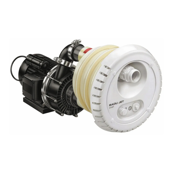
    Beschreibung Beschreibung Komponenten (92) (54/1) (21/1) (38/1) WG23.50.049-P Abb. 1 (21/1) Luftregulierung Einbaugehäuse (38/1) Pneumatiktaster Pumpe (54/1) Düse (92) Pumpe Funktion Die Pumpe (92) ist über die Saug- und Druckleitung mit dem Kunststoff-Einbaugehäuse (1) verbunden. Mit dem Pneumatiktaster (38/1) wird die Pumpe EIN/AUS geschaltet. Über den umlaufenden Ringkanal im Gehäuse wird das Badewasser mit geringer Strömung von der Jet-Pumpe (92) angesaugt und mit hohem Druck über die Düse (54/1) in das Becken...
  • Seite 19: Transport Und Zwischenlagerung

    Transport und Zwischenlagerung Transport und Zwischenlagerung Transport  Lieferzustand kontrollieren. – Verpackung auf Transportschäden prüfen. – Schaden feststellen, mit Bildern dokumentieren und an den Händler wenden. Pumpe anheben GEFAHR Tod oder Quetschungen von Gliedmaßen durch herabfallendes Transportgut! Die Tragösen am Motor sind nur für das Gewicht des Motors ausgelegt.
  • Seite 20: Lagerung

    Transport und Zwischenlagerung Lagerung HINWEIS Korrosion durch Lagerung in feuchter Luft bei wechselnden Temperaturen! Kondenswasser kann Wicklungen und Metallteile angreifen.  Pumpe/Anlage in trockener Umgebung bei möglichst konstanter Temperatur zwischenlagern. HINWEIS Beschädigung oder Verlust von Einzelteilen!  Originalverpackung erst vor dem Einbau öffnen beziehungsweise Einzelteile bis zum Einbau in der Originalverpackung aufbewahren.
  • Seite 21: Installation

    Installation Installation Einbauort (Fachpersonal) 5.1.1 Aufstellen im Freien Um die Lebensdauer der Pumpe zu erhöhen, einen  einfachen Regenschutz vorsehen. 5.1.2 Einbaustelle  Der Einbau der Anlage erfolgt im Normalfall an der Schmalseite des Beckens, mit einer empfohlenen Mindestbeckenlänge von 4 m. ...
  • Seite 22: Körper- Und Luftschallübertragung

    Installation 5.1.5 Körper- und Luftschallübertragung  Vorschriften für baulichen Schallschutz beachten, zum Beispiel DIN 4109.  Pumpe so aufstellen, dass die Körper- und Luftschallübertragungen reduziert werden. Als Unterlage eignen sich schwingungsabsorbierende Materialien. Beispiele: – Schwingmetallpuffer – Korkeinlagen – Schaumstoffe mit ausreichender Härte 5.1.6 Platzreserve ...
  • Seite 23: Aufstellung (Fachpersonal)

    Installation Aufstellung (Fachpersonal) 5.2.1 Einbauhinweis Betonbecken Betonbecken mit Folie Spannring Folie Beton Einbaugehäuse Düsengehäuse Dichtungen WG23.50.068-1-P Abb. 3 Betonbecken gefliest Spannringe Fliesen Beton Einbaugehäuse Düsengehäuse Dichtung WG23.50.069-1-P Abb. 4 03|2019 DE 21...
  • Seite 24: Einbau An Schalung Des Betonbeckens

    Installation Beckenausschnitt für Betonbecken/Schalung Düse Ø7 4) Befestigung an der Schalung (4x) WG23.50.036-2-1-P Abb. 5 Einbau an Schalung des Betonbeckens Schalungshilfe Druckanschluss (B) Muffe 25mm Noppendichtung Schutzkappe GPN600 B198 Sauganschluss (C) Schraube KB60 x 40 Einbaugehäuse Schalung Schalung WG23.70.032-1-P Maße in cm Abb.
  • Seite 25 Installation Montage des Einbaugehäuses in ein Betonbecken HINWEIS Schrauben nur handfest anziehen. Keine Gewalt anwenden! Druckanschluss (B) oben, über dem Sauganschluss (C) anordnen. Einbautiefe: Mitte der Düse soll 25 cm unterhalb des Wasserspiegels angebracht werden. Noppendichtung (26) in das Gehäuse (1) einlegen. Einbaugehäuse (1) ausrichten und mit vier Schneidschrauben (103) an Schalung befestigen.
  • Seite 26 Installation Montage des Einbaugehäuses in ein gefliestes Betonbecken  5.2.3 beachten: Ausrichtung des Spannrings WG23.50.051-P Abb. 8 In einem gefliesten Becken wird die Fliesenstärke mit einem zusätzlichen Spannring (28) und längeren Schneidschrauben (52) ausgeglichen. Diese Teile sind im Zusatz-Kit optional erhältlich. 24 DE 03|2019...
  • Seite 27: Einbauhinweis Folien- /Polyesterbecken

    Installation 5.2.2 Einbauhinweis Folien- /Polyesterbecken Folienbecken Spannring Folie Beckenwand Einbaugehäuse Düsengehäuse Dichtungen WG23.50.070-1-P Abb. 9 Polyesterbecken Spannring Beckenwand Einbaugehäuse Düsengehäuse Dichtungen WG23.50.071-1-P Abb. 10 03|2019 DE 25...
  • Seite 28 Installation Beckenausschnitt für Folienbecken/Polyesterbecken Düse Ø7 1) Befestigung Spannring (10x) 2) Befestigung Düsengehäuse (4x) 3) Befestigung an der Beckenwand (2x) WG23.50.036-1-P Abb. 11 26 DE 03|2019...
  • Seite 29 Installation Montage des Einbaugehäuses in ein Folien-, Polyester-, Stahl- oder Alubecken (A) HINWEIS Schrauben nur handfest anziehen. Keine Gewalt anwenden. Druckanschluss (B) oben, über dem Sauganschluss (C) anordnen. Einbautiefe: Mitte der Düse soll 25 cm unterhalb des Wasserspiegels angebracht werden. Durchgangsbohrungen mit Hilfe der beiliegenden Bohrschablone bohren.
  • Seite 30 Installation Montage des Einbaugehäuses in ein Polyesterbecken (A)  5.2.3 beachten: Ausrichtung des Spannrings WG23.50.052-P Abb. 12 Montage des Einbaugehäuses in ein Folienbecken (A)  5.2.3 beachten: Ausrichtung des Spannrings WG23.50.053-P Abb. 13 28 DE 03|2019...
  • Seite 31: Ausrichtung Des Spannrings

    Installation 5.2.3 Ausrichtung des Spannrings Die vier mit (1) markierten Bohrungen müssen immer im 45°- Winkel zur Mittelachse stehen. Oben Oben WG23.50.054-1-P Abb. 14 5.2.4 Schutzschlauch und Schlauch für Luftregulierung Schutzschlauch und Schlauch für Luftregulierung über den Wasserspiegel führen und befestigen. 5.2.5 Rohrleitungen dimensionieren Zu lange Saugleitungen haben erhebliche Nachteile:...
  • Seite 32: Rohrleitungen Verlegen

    Installation 5.2.6 Rohrleitungen verlegen HINWEIS Einbaugehäuse und Verschraubungen sind aus ABS. Eine Aushärtezeit der Verklebung von mindestens zwölf Stunden muss berücksichtigt werden!  Saug- und Druckleitung möglichst kurz und gerade halten.  Saug- und Druckleitung unter Niveau des Wasserspiegels verlegen. ...
  • Seite 33: Fertigmontage (Fachpersonal)

    Installation Fertigmontage (Fachpersonal) WARNUNG Verletzungen durch Ansaugen/Ansaugwirkung durch nicht montierte Ansaugblende!  Ansaugblende unbedingt montieren. Für Schäden, die auf Zuwiderhandlung oder fehlerhafte Montage zurückzuführen sind, erlöschen sämtliche Garantie- und Schadensersatzansprüche. HINWEIS Schrauben nur handfest anziehen. Keine Gewalt anwenden! Nach dem Einbau des Einbaugehäuses (Vormontagesatz): Einkleben des Kabelschutzschlauches und des Luftleitungsschlauches.
  • Seite 34 Installation Druckanschluss (B) Luftleitung Pneumatikleitung Sauganschluss (C) WG23.50.055-1-P Abb. 15 32 DE 03|2019...
  • Seite 35: Einbaubeispiel Standard-Ausführung

    Installation 5.3.1 Einbaubeispiel Standard-Ausführung Be- und Entlüftung DN 100 Schachtbreite min. 70 cm Schaltanlage im trockenen Raum und über dem Wasserspiegel montieren Schlauch für Luftregulierung und Pneumatiktaster über den Wasserspiegel führen und befestigen Be- und Entlüftung zur Vermeidung von Kondenswasser Pumpe auf einem Sockel oder ähnlicher Unterlage montieren Maße in cm...
  • Seite 36: Pumpe Aufstellen Und An Die Rohrleitung Anschließen

    Installation 5.3.3 Pumpe aufstellen und an die Rohrleitung anschließen Pumpe horizontal auf einer schwingungsabsorbierenden Unterlage befestigen. HINWEIS Beschädigung der Pumpe durch unzulässige mechanische Spannungen! Rohrleitung unmittelbar vor der Pumpe abstützen und  spannungsfrei anschließen. Rohrleitungen spannungsfrei gemäß VDMA-Einheitsblatt 24277 anschließen. Gegebenenfalls Kompensatoren verwenden.
  • Seite 37: Elektrischer Anschluss Der Gegenstromanlage

    Installation WARNUNG Stromschlaggefahr durch Spannung am Gehäuse! Bei Pumpen mit Drehstrom- oder mit Wechselstrommotor  ohne Motorschutz, muss ein korrekt eingestellter Motorschutzschalter installiert werden. Dabei die Werte auf dem Typenschild beachten. Stromkreis mit einer Fehlerstromschutzeinrichtung,  Nennfehlerstrom I ≤ 30 mA, schützen. ...
  • Seite 38: Anschlussschema

    Installation 5.4.2 Anschlussschema Abb. 18 36 DE 03|2019...
  • Seite 39: Demontage

    Installation Demontage  Kapitel „"Außerbetriebnahme" auf Seite 40“ beachten. Kabelverschraubung (20) lösen. Schutzkappe (96) abnehmen. Vier Schrauben (95) lösen. Düsengehäuse (102.1) herausziehen. Schlauchklemme (8) öffnen. Düsengehäuse (102.1) abnehmen. Zehn Schrauben (52) lösen. Spannring (28) und Spannringdichtung (27) abnehmen. 03|2019 DE 37...
  • Seite 40: Inbetriebnahme/Außerbetriebnahme

    Inbetriebnahme/Außerbetriebnahme Inbetriebnahme/Außerbetriebnahme Inbetriebnahme HINWEIS Beschädigung der Pumpe/Anlage durch Trockenlauf!  Sicherstellen, dass die Pumpe/Anlage immer mit Wasser gefüllt ist. Dies gilt auch bei der Drehrichtungskontrolle. 6.1.1 Pumpe auf Leichtgängigkeit prüfen Nach längerer Stillstandszeit muss die Pumpe im ausgeschalteten und spannungsfreien Zustand auf Leichtgängigkeit geprüft werden.
  • Seite 41: Betrieb

    Inbetriebnahme/Außerbetriebnahme Betrieb 6.2.1 Ein-/ Ausschalten Die Anlage wird durch Drücken des in der Blende eingebauten Pneumatiktasters (38/1) ein- und ausgeschalten. Es gibt keine elektrische Betätigungseinheit im Becken. 6.2.2 Mengenregulierung Mit der regulierbaren Düse (54/1) kann der Förderstrom und damit die Wirkung der Anlage individuell für den Schwimmer eingestellt werden.
  • Seite 42: Verwendung Des Massageschlauches

    Inbetriebnahme/Außerbetriebnahme Verwendung des Massageschlauches WARNUNG Verletzung durch falsche Benutzung!  Verwendung des Massageschlauches sollte nur nach ärztlicher Rücksprache an den betroffenen Körperstellen erfolgen. Bei Zweckentfremdung des Massageschlauches wird keine Haftung übernommen.  Kinder dürfen den Massageschlauch nicht benutzen. Mengenregulierung (54/1) in der Gegenstromanlage schließen.
  • Seite 43: Montage Der Blindplatte

    Inbetriebnahme/Außerbetriebnahme Abstützung WG23.50.058-1-P Abb. 19 6.4.2 Montage der Blindplatte Um die Blindplatte zu montieren, sind folgende Schritte notwendig: Kapitel "Demontage" auf Seite 37 beachten. Blindplatte (30) unter Spannring (28) ansetzen und mit vier Schneidschrauben (103) am Einbaugehäuse (1) befestigen. Siehe "Abb. 12" auf Seite 28 und Siehe "Abb. 13" auf Seite 03|2019 DE 41...
  • Seite 44: Störungen

    Störungen Störungen HINWEIS Es ist normal, dass von Zeit zu Zeit einige Tropfen Wasser durch die Gleitringdichtung austreten. Das gilt insbesondere während der Einlaufzeit. Je nach Wasserbeschaffenheit und Betriebsstundenzahl kann die Gleitringdichtung undicht werden.  Bei permanentem Wasseraustritt Gleitringdichtung von einem Fachmann wechseln lassen.
  • Seite 45 Störungen Störung: Leckage an der Pumpe. Mögliche Ursache Abhilfe Gleitringdichtung verschlissen  Gleitringdichtung von einem Fachmann oder beschädigt. auswechseln lassen. Störung: Laute Motorgeräusche. Mögliche Ursache Abhilfe Kugellager defekt.  Kugellager von einem Fachmann auswechseln lassen. Falsche Drehrichtung (3~).  Durch Elekrofachkraft prüfen lassen.
  • Seite 46: Pumpe Nach Ansprechen Eines Schutzkontakts/-Schalters Prüfen

    Störungen 7.1.1 Pumpe nach Ansprechen eines Schutzkontakts/-schalters prüfen Wurde der Motor durch den Wicklungsschutzkontakt oder den Motorschutzschalter ausgeschaltet, folgende Schritte durchführen: Anlage von der Spannungsversorgung trennen. Motorwelle lüfterseitig mit einem Schraubendreher durchdrehen und auf Leichtgängigkeit prüfen. Motorwelle schwergängig: Schraubendreher entfernen. Kundendienst/Schwimmbadbauer verständigen und Pumpe prüfen lassen.
  • Seite 47: Wartung/Instandhaltung

    Wartung/Instandhaltung Wartung/Instandhaltung HINWEIS  Vor Instandhaltungsarbeiten alle Absperrarmaturen schließen und Leitungen entleeren. Wann? Was? Regelmäßig  Ansaugöffnung von Fremdkörpern befreien.  Motorwelle durchdrehen (bei längerem Stillstand).  Verschraubungen nachziehen. Bei Frostgefahr  Pumpe und frostgefährdete Leitungen rechtzeitig entleeren.  Nach Beendigung der Instandhaltungsarbeiten alle erforderlichen Maßnahmen für die Inbetriebnahme ergreifen.
  • Seite 48: Austausch Des Pneumatiktasters

    Wartung/Instandhaltung Austausch des Pneumatiktasters WG23.50.072-P Abb. 20 Montage des Pneumatiktasters in umgekehrter Reihenfolge. Entfernen des Düsengehäuses siehe Kapitel „5.5 Demontage“ bis Punkt 4. 46 DE 03|2019...
  • Seite 49: Gewährleistung

    Wartung/Instandhaltung Gewährleistung Die Gewährleistung erstreckt sich auf die gelieferten Geräte mit allen Teilen. Ausgenommen sind jedoch natürliche Abnutzung/Verschleiß (DIN 3151/DIN-EN 13306) aller drehenden beziehungsweise dynamisch beanspruchter Bauteile, einschließlich spannungsbelasteter Elektronik-Komponenten. Die Nichtbeachtung der Sicherheitshinweise kann zum Verlust jeglicher Schadensersatzansprüche führen. 8.2.1 Sicherheitsrelevante Ersatzteile –...
  • Seite 50: Entsorgung

    Entsorgung Entsorgung Schädliche Fördermedien auffangen und vorschriftsgemäß  entsorgen.  Die Pumpe/Anlage beziehungsweise die Einzelteile müssen nach Lebensdauerende fachgerecht entsorgt werden. Eine Entsorgung im Hausmüll ist nicht zulässig!  Verpackungsmaterial, unter Beachtung der örtlichen Vorschriften, im Hausmüll entsorgen. 48 DE 03|2019...
  • Seite 51: Technische Daten

    Technische Daten Technische Daten Technische Daten 50 Hz BADU Jet Smart Jet Pumpe 21-50/44 GT 21-50/43 GT 27° 27° Förderstrom Pumpe [m³/h] Spannung 400/230 V 230 V/Y Leistungsaufnahme P [kW] 2,55 2,27 Leistungsabgabe P [kW] 2,20 1,60 Anzahl Düsen (40 mm) Ausströmdruck an Düsen...
  • Seite 52: 10.1 Maßzeichnung

    Technische Daten 10.1 Maßzeichnung Nicht eingeklebt! Sauganschluss ca. 23 Nicht eingeklebt! Druckanschluss WG23.50.038-1-P Abb. 21 50 DE 03|2019...
  • Seite 53: 10.2 Explosionszeichnung

    Technische Daten 10.2 Explosionszeichnung Abb. 22 03|2019 DE 51...
  • Seite 54: Index

    Index Index Gleitringdichtung 44 Aufstellung 23 Außerbetriebnahme 39, 40, 42 Inbetriebnahme 40 Installation 21 Instandhaltung 47 Bestimmungsgemäße Verwendung 9 Betrieb 41 Lagerung 20 Demontage 39, 43 Störungen 13, 44 Elektrischer Anschluss 36 Entsorgung 51 Technische Daten 52 Ersatzteile 10 Transport 19 Fachpersonal 21, 23, 36 Überwinterungsvorschlag 42 Frost 16...
  • Seite 55 Translation of original operation manual Smart Submerged counter swim unit WG23.50.060-P...
  • Seite 56 BADU ® is a trademark of SPECK Pumpen Verkaufsgesellschaft GmbH Hauptstraße 3 91233 Neunkirchen am Sand, Germany Phone +49 9123 949-0 +49 9123 949-260 info@speck-pumps.com www.speck-pumps.com All rights reserved. Contents may not be distributed, duplicated, edited or transferred to third parties without the written permission of SPECK Pumpen Verkaufsgesellschaft GmbH.
  • Seite 57 Table of contents Table of contents About this document ............... 7 Using this manual ..............7 Target group................7 Other applicable documents ............7 1.3.1 Symbols and means of representation ........7 Safety ....................9 Intended use ................9 2.1.1 Possible misuse ..............
  • Seite 58 Table of contents Function .................. 15 Transport and intermediate storage ..........16 Transport ................. 16 Lifting the pump ............... 16 Storage ................... 17 Returns ................... 17 Installation ..................18 Installation site (Qualified specialist) ........18 5.1.1 Outdoor installation ............. 18 5.1.2 Installation position ..............
  • Seite 59 Table of contents 6.1.2 Switching the pump on ............37 Operation ................38 6.2.1 Switching the unit on and off ..........38 6.2.2 Volume regulator ..............38 6.2.3 Ball nozzle(s) ............... 38 6.2.4 Air regulator ................. 38 6.2.5 Optional accessories ............38 Using the massage hose ............
  • Seite 60 Glossary Unit Pump built into the system. Pressure line Pipe connected to the pressure discharge. Pump Machine with motor. Suction line Pipe connected to the suction discharge. 6 EN 03|2019...
  • Seite 61: About This Document

    About this document About this document Using this manual This manual is a component of the pump/unit. The pump/unit was manufactured and tested according to the generally accepted rules of technology. However, if the pump/unit is used incorrectly, not serviced enough or tampered with, danger to life and limb or material damage could result.
  • Seite 62 About this document NOTICE Notes to prevent material damage, for better understanding or to optimise the workflow. Important information and technical notes are specially marked to explain correct operation. Symbol Meaning  Instructions for a one-step action. Directions for a multi-step action. ...
  • Seite 63: Safety

    Safety Safety Intended use For installation in all types of swimming pool as a talking point, for fitness training, as a wave or air bubble bath, for underwater massage, after medical consultation, for endless no-turn swimming. Observing the following information is vital for intended use: •...
  • Seite 64: Safety Regulations

    Safety – The personnels' responsibilities, for example working on the product, electric equipment or hydraulic systems, are set based on their qualifications and the job description. – The personnel have read this manual and understand the necessary working steps. Safety regulations The operator of the system is responsible for the adherence to all relevant statutory regulations and guidelines.
  • Seite 65: Rotating Parts

    Safety Only use hoisting and load-bearing equipment which is  suitable and technically sound.  Do not stand under suspended loads. 2.7.2 Rotating parts There is a risk of shearing and crushing due to exposed rotating parts.  Only perform servicing when the pump/unit is not in operation.
  • Seite 66: Suction Danger

    Safety 2.7.5 Suction danger The following dangers can lead to drowing: – Sucking towards, sucking in or jamming of the body or body parts, clothing and jewellery – Knotting of the hair  Never operate the system without a suction cover, cover or a light cover if applicable.
  • Seite 67: Dry Running

    Safety Install the pump/unit in a manner which reduces structure-  borne and airborne noise transmission. When doing so, observe relevant regulations. If the pipe forces are exceeded, leaks can occur at the screwed connection or the pump itself.  Do not use the pump as a fixed point for the pipe line.
  • Seite 68: Pressure Surges

    Safety 2.9.5 Pressure surges Valves which close suddenly can cause pressure surges which far exceed the maximum permissible housing pressure of the pump.  Avoid valves which close suddenly or, if present, close them slowly. 2.9.6 Blockages in the pump Pieces of dirt in the suction line can clog and block the pump.
  • Seite 69: Description

    Description Description Components (92) (54/1) (21/1) (38/1) WG23.50.049-P Fig. 1 Main housing (21/1) Air regulator (38/1) Pneumatic button pump (54/1) Nozzle (92) Pump Function The pump (92) is connected via the suction and pressure line with the plastic main housing (1). The pump is switched ON/OFF with the pneumatic button (38/1).
  • Seite 70: Transport And Intermediate Storage

    Transport and intermediate storage Transport and intermediate storage Transport  Check the delivery conditions. – Check the packaging for transport damage. – Determine damages, document them with photographs and contact the distributor. Lifting the pump DANGER Goods being transported can fall and result in death or crushing of limbs! The lifting hooks on the motor are designed for the weight of the motor.
  • Seite 71: Storage

    Transport and intermediate storage Storage NOTICE Corrosion is possible due to storage in humid conditions with fluctuating temperatures! Condensation can corrode windings and metal parts.  Store the pump/unit in a dry environment at a temperature which is as constant as possible. NOTICE Damage or loss of individual parts! ...
  • Seite 72: Installation

    Installation Installation Installation site (Qualified specialist) 5.1.1 Outdoor installation In order to increase the pump's service life, provide simple  weather protection. 5.1.2 Installation position  The unit is normally installed on the narrow side of the pool with a recommended minimum pool length of 4 m. ...
  • Seite 73: Structure-Borne And Airborne Noise Transmission

    Installation 5.1.5 Structure-borne and airborne noise transmission  Observe regulations for structural noise protection, for example DIN 4109.  Install the pump in a manner which reduces structure-borne and airborne noise transmission. Vibration-absorbing materials are suitable bases. Examples: – Anti-vibration buffers –...
  • Seite 74: Installation (Qualified Specialist)

    Installation Installation (Qualified specialist) 5.2.1 Installation tip concrete pool Concrete pool with foil Support ring Foil Concrete Main hosuing Nozzle housing Seals WG23.50.068-2-P Fig. 3 Tiled concrete pool Support ring Tiles Concrete Main housing Nozzle housing Seal WG23.50.069-2-P Fig. 4 20 EN 03|2019...
  • Seite 75 Installation Pool cutout for concrete pools/formwork Nozzle Ø7 4) Fastening to the formwork (4x) WG23.50.036-2-2-P Fig. 5 Installation of formwork for concrete pools Formwork aid Socket 25mm Nub seal Protective cover GPN600 B198 Screw KB60 x 40 Main housing Formwork Formwork dimensions in cm WG23.70.032-2-P...
  • Seite 76 Installation Mounting the main housing in a concrete pool NOTICE Only tighten the screws hand-tight. Do not use any force! Position the top outlet connection (B) above the inlet connection (C). Installation depth: The middle of the nozzle should be attached 25 cm below the water level.
  • Seite 77 Installation Mounting the main housing in a tiled concrete pool  Observe 5.2.3: Aligning the support ring WG23.50.051-P Fig. 8 In a tiled pool the tile thickness is compensated for with an additional support ring (28) and longer tapping screws (52). The parts are optionally available in the additional kit.
  • Seite 78: Installation Tip Foil/Polyester Pools

    Installation 5.2.2 Installation tip foil/polyester pools Foil pool Support ring Foil Pool wall Main hosuing Nozzle housing Seals WG23.50.070-2-P Fig. 9 Polyester pool Support ring Pool wall Main hosuing Nozzle housing Seals WG23.50.071-2-P Fig. 10 24 EN 03|2019...
  • Seite 79 Installation Pool cut-out for foil/poyester pools Nozzle Ø7 1) Fastening support ring (10x) 2) Fastening nozzle housing (4x) 3) Fastening jet housing to the wall (2x) WG23.50.036-2-P Fig. 11 03|2019 EN 25...
  • Seite 80 Installation Mounting the main housing in a foil, polyester, steel or aluminium pool (A) NOTICE Only tighten the screws hand-tight. Do not use any force! Position the top outlet connection (B) above the inlet connection (C). Installation depth: The middle of the nozzle should be attached 25 cm below the water level.
  • Seite 81 Installation Mounting the main housing in a polyester pool (A)  Observe 5.2.3: Aligning the support ring WG23.50.052-P Fig. 12 Mounting the main housing in a foil pool (A)  Observe 5.2.3: Aligning the support ring WG23.50.053-P Fig. 13 03|2019 EN 27...
  • Seite 82: Aligning The Support Ring

    Installation 5.2.3 Aligning the support ring The four holes marked (1) must always be positioned at a 45° angle to the centre axis. WG23.50.054-2-P Fig. 14 5.2.4 Protective conduit and hose for air regulator Lay and fasten the protective conduit and the hose for the air regulator above the water level.
  • Seite 83: Laying Pipes

    Installation 5.2.6 Laying pipes NOTICE The main housing and the screw connections are made of ABS. A curing time of at least 12 hours for the bonding must be observed!  Keep the suction and pressure lines as short and straight as possible.
  • Seite 84: Final Assembly (Qualified Specialist)

    Installation Final assembly (Qualified specialist) WARNING Injury due to suction if the suction panel is not mounted!  It is imperative that the suction panel is mounted. All guarantee rights and claims for compensation are rendered invalid for damage resulting from the suction panel not being mounted or being mounting incorrectly.
  • Seite 85 Installation Outlet connection (B) Air control tube Pneumatic switch tube Inlet connection (C) WG23.50.055-2-P Fig. 15 03|2019 EN 31...
  • Seite 86: Installation Example: Standard Version

    Installation 5.3.1 Installation example: standard version Aeration and ventilation DN 100 Shaft width min. 70 cm Mount switchgear in dry room and above the water level Lay and fasten the hose fo the air regulation and pneumatic button above the water level Aeration and ventilation to avoid the condensation Mount the pump on a base or similar foundation...
  • Seite 87: Installing The Pump And Connecting It To The Pipework

    Installation 5.3.3 Installing the pump and connecting it to the pipework Fasten the pump horizontally on a vibration-absorbing base. NOTICE The pump can be damaged by unauthorised mechanical strains being placed on the pump!  Take the pipe up directly before the pump and connect it free of tension.
  • Seite 88: Counter Swim Unit Electrical Connection

    Installation Only use suitable pipe types according to regional  regulations.  Adjust minimum diameter of the electrical pipes to accommodate the motor output and pipe length.  Do not bend or squash the pipes.  If hazardous situations can occur, provide an emergency off switch according to DIN EN 809.
  • Seite 89: Connection Diagram

    Installation 5.4.2 Connection diagram Fig. 18 03|2019 EN 35...
  • Seite 90: Disassembly

    Installation Disassembly  Observe point "Decommissioning" on page 39 Loosen the cable screws (20). Remove the protection cap (96). Loosen the four screws (95). Extract the nozzle housing (102.1). Open the hose clamps (8). Remove the nozzle housing (102.1). Loosen the ten screws (52). Remove the clamping ring (28) and clamping ring seal (27).
  • Seite 91: Commissioning/Decommissioning

    Commissioning/Decommissioning Commissioning/Decommissioning Commissioning NOTICE The pump/unit can be damaged if it runs dry!  Ensure that the pump/unit is always full of water. This also applies to checking the rotation direction. 6.1.1 Checking how easily the pump rotates After longer idle periods, the pump must be checked for how easily it rotates while it is switched off.
  • Seite 92: Operation

    Commissioning/Decommissioning Operation 6.2.1 Switching the unit on and off The unit can be switched on and off by pressing the pneumatic button (38/1) which is built into the cover. There is no electrical operating unit in the pool. 6.2.2 Volume regulator The flow rate, and therefore the unit's effect, can be set individually for the swimmer using the adjustable nozzle (54/1).
  • Seite 93: Using The Massage Hose

    Commissioning/Decommissioning Using the massage hose WARNING Injury due to incorrect use!  Consult a doctor before using the massage hose on the affected body parts. No liability is accepted for misuse of the massage hose.  Children may not use the massage hose! Close the volume regulator (54/1) in the counter swim unit.
  • Seite 94: Assembling The Dummy Plate

    Commissioning/Decommissioning Support WG23.50.058-2-P Fig. 19 6.4.2 Assembling the dummy plate The following steps are necessary in order to assemble the dummy plate: Observe the point "Disassembly" on page 36. Attach the dummy plate (30) under the support ring (28) and fasten it to the main housing (1) using four tapping screws (103).
  • Seite 95 Faults Faults NOTICE It is normal for a few drops of water to escape from the mechanical seal from time to time. This is especially true during the break-in period. Depending on the water quality and number of operating hours, the mechanical seal can begin to leak.
  • Seite 96: Faults

    Faults Problem: Pump leaks. Possible cause Solution Mechanical seal is worn or  Have a professional replace the mechanical damaged. seal. Problem: Loud motor noise. Possible cause Solution Faulty ball bearings.  Have a mechanic replace the ball bearings. Direction of rotation is wrong Have a qualified ...
  • Seite 97: Spare Parts Lists

    Faults NOTICE If the pump seizes and is repeatedly switched on, the motor can be damaged.  Ensure that the pump/unit is only switched on once. Wait until the built-in overload switch automatically switches the motor on after it has cooled down. –...
  • Seite 98 Maintenance Maintenance NOTICE  Before maintenance work, close all shut-off valves and drain all pipes. When? What? Regularly  Remove foreign matter from the suction opening.  Turn the motor shaft (after long idle periods).  Tighten the screws. If there is a chance ...
  • Seite 99: Maintenance

    Maintenance Replacing the pneumatic button WG23.50.072-P Fig. 20 Assembly of the pneumatic button in reverse order. To remove the nozzle housing see point “5.5 Disassembly” up to point 4. 03|2019 EN 45...
  • Seite 100: Warranty

    Maintenance Warranty The warranty includes the devices delivered and all components. However natural wear and tear (DIN 3151/DIN-EN 13306) on all turning and dynamically loaded components, including electronic components under tension, is not covered under the warranty. Failure to comply with the safety instructions may void the warranty.
  • Seite 101: Disposal

    Disposal Disposal Collect harmful media and dispose of it according to the  regulations.  At the end of its service life, the pump/unit or individual components must be disposed of correctly. Disposal in the household waste is not permitted! ...
  • Seite 102: Technical Data

    Technical data Technical data Technical data at 50 Hz BADUJET Smart Jet pump 21-50/44 GT 21-50/43 GT 27° 27° Pump flow rate [m³/h] Voltage 400/230 V 230 V/ Y Power input P [kW] 2.55 2.27 Power output P [kW] 2.20 1.60 Number of nozzles (40 mm) Outlet pressure at nozzle...
  • Seite 103: 10.1 Dimensional Drawing

    Technical data 10.1 Dimensional drawing Not glued! Outlet connection ca. 23 Not glued! Inlet connection WG23.50.038-2-P Fig. 21 03|2019 EN 49...
  • Seite 104: 10.2 Exploded Drawing

    Technical data 10.2 Exploded drawing Fig. 22 50 EN 03|2019...
  • Seite 105: Index

    Index Index Mechanical seal 42 Commissioning 38 Operation 39 Decommissioning 37, 38, 40 Disassembly 37, 41 Qualified specialist 19, 21, 34 Disposal 48 Spare parts 11 Electrical connection 34 Storage 18 Suggestion for winter conditions 40 Faults 13, 42 Frost 15 Technical data 49 Transport 17 Installation 19, 21...
  • Seite 107 Traduction des instructions d'utilisation originale Smart Installation de nage à contre-courant encastrée WG23.50.060-P...
  • Seite 108 BADU ® est une marque de SPECK Pumpen Verkaufsgesellschaft GmbH Hauptstraße 3 91233 Neunkirchen am Sand, Allemagne Téléphone +49 9123 949-0 +49 9123 949-260 info@speck-pumps.com www.speck-pumps.com Tous droits réservés. Le contenu ne doit pas être distribué, copié, modifié ou encore cédé à un tiers sans l'accord écrit de la société...
  • Seite 109 Sommaire Sommaire A propos de ce document ............... 7 Utilisation de ce manuel ............7 Groupe ciblé ................7 Documents annexes ..............7 1.3.1 Symboles et représentations graphiques ......7 Sécurité .................... 9 Utilisation conforme aux dispositions ........9 2.1.1 Erreurs de manipulation possibles ........
  • Seite 110 Sommaire Fonctionnement ..............16 Transport et stockage intermédiaire ..........17 Transport ................. 17 Soulever la pompe ..............17 Stockage ................. 18 Retour ..................18 Installation ..................19 Lieu de montage (Personnel qualifié) ........19 5.1.1 Installation en plein air ............19 5.1.2 Lieu de montage..............
  • Seite 111 Sommaire Mise en service ............... 38 6.1.1 Vérifier le bon fonctionnement de la pompe ......38 6.1.2 Démarrer la pompe ............. 38 Fonctionnement ..............39 6.2.1 Mise en marche/à l'arrêt ............39 6.2.2 Régulation du débit ............. 39 6.2.3 Filière(s) à billes ..............39 6.2.4 Régulation d'air ..............
  • Seite 112 Glossaire Installation Pompe intégrée dans le système. Tuyauterie de refoulement Tuyauterie raccordée à la tubulure de refoulement. Pompe Machine avec entraînement. Tuyauterie d'aspiration Tuyauterie raccordée à la tubulure d'aspiration. 6 FR 03|2019...
  • Seite 113: Propos De Ce Document

    A propos de ce document A propos de ce document Utilisation de ce manuel Ce mode d'emploi est inclus dans le colis de la pompe/l'installation. La pompe/l'installation a été fabriquée et contrôlée selon les règles techniques reconnues. Malgré cela, en cas d'utilisation inappropriée, de maintenance insuffisante ou d'interventions non autorisées, des risques de blessure et de mort ainsi que de dommages matériels peuvent se présenter.
  • Seite 114 A propos de ce document AVERTISSEMENT Dangers pour les personnes. Le non-respect de ces consignes peut entraîner la mort ou des blessures graves. ATTENTION Dangers pour les personnes. Le non-respect peut conduire à des blessures légères voire graves. AVIS Recommandations pour éviter les dégâts matériels, améliorer la compréhension ou optimiser le déroulement des opérations.
  • Seite 115: Sécurité

    Sécurité Sécurité Utilisation conforme aux dispositions Pour le montage dans tous les types de piscines comme attraction, pour l´activité physique, comme piscine à remous ou bain à bulles, pour le massage subaquatique sur avis médical, pour nager contre le courant. Une utilisation correcte implique la prise en compte de toutes les informations suivantes : •...
  • Seite 116: Consignes De Sécurité

    Sécurité – Pour les travaux sur la partie mécanique, comme le changement des roulements à bille ou de la garniture mécanique : mécanicien qualifié. – Pour les travaux sur le système électrique : électricien qualifié.  Assurez-vous que les conditions préalables suivantes sont remplies: –...
  • Seite 117: Changements De La Structure Et Pièces Détachées

    Sécurité Changements de la structure et pièces détachées Les transformations ou modifications peuvent compromettre la sécurité de l’installation.  Transformer ou modifier la pompe/l'installation uniquement après avoir consulté le fabricant.  Utiliser uniquement des pièces détachées ou accessoires d'origine autorisés par le fabricant. Plaques signalétiques ...
  • Seite 118: Surfaces Chaudes

    Sécurité Respecter les directives VDE et EVU de l'entreprise  d'exploitation et de distribution d'énergie.  Construire la piscine avec un champ de protection conformément à la norme DIN VDE 0100-702.  Avant d'effectuer des travaux sur l'installation électrique, prendre les mesures suivantes: –...
  • Seite 119: Pannes

    Sécurité Pannes  En cas de pannes, couper et débrancher immédiatement l'installation.  Remédier immédiatement à tout dysfonctionnement. Pompe bloquée En cas de de démarrage répétitif d'une pompe bloquée, le moteur peut être endommagé. Veuillez respecter les points suivants : ...
  • Seite 120: Fonctionnement Sans Eau

    Sécurité 2.9.2 Fonctionnement sans eau En cas de fonctionnement de la pompe sans eau, la garniture mécanique et les pièces en matière plastique peuvent être détruites en l'espace de quelques secondes.  Ne pas faire fonctionner la pompe sans eau. Cela vaut également pour le contrôle du sens de rotation.
  • Seite 121: Blocage De La Pompe

    Sécurité 2.9.6 Blocage de la pompe Des impuretés dans la conduite d'aspiration peuvent boucher et bloquer la pompe.  Dégager l'ouverture d'aspiration des corps étrangers (branches, feuilles mortes, vêtements, ...).  Vérifier le bon fonctionnement de la pompe avant la mise en marche ou avant un long temps d´arrêt ou de stockage.
  • Seite 122: Description

    Description Description Composants (92) (54/1) (21/1) (38/1) WG23.50.049-P Fig. 1 Pièce à sceller (21/1) Régulation d’air (38/1) Commande pneumtique de (54/1) Buse la pompe (92) Pompe Fonctionnement La pompe (92) est reliée par les tuyauteries d'aspiration et de refoulement à la pièce à sceller en matière plastique (1). Avec la commande pneumatique (38/1), on commute la pompe sur MARCHE/ARRET.
  • Seite 123: Transport Et Stockage Intermédiaire

    Transport et stockage intermédiaire Transport et stockage intermédiaire Transport  Contrôler la livraison. – Vérifier si l'emballage n’a pas subi de dommages liés au transport. – Localiser le dommage, le documenter avec des photos et contacter le revendeur. Soulever la pompe DANGER Risque de décès ou d'écrasement des membres suite à...
  • Seite 124: Stockage

    Transport et stockage intermédiaire Stockage AVIS Corrosion due à un stockage dans un environnement humide et sujet aux variations de température! La condensation peut endommager le bobinage et les pièces métalliques. Stockage intermédiaire de la pompe/l'installation dans un lieu  sec et à...
  • Seite 125: Installation

    Installation Installation Lieu de montage (Personnel qualifié) 5.1.1 Installation en plein air Prévoir une simple protection contre la pluie afin d'augmenter  la durée de vie de la pompe. 5.1.2 Lieu de montage  En règle générale, la NCC est encastrée dans la largeur de la piscine avec une longueur minimale de bassin recommandée de 4 m.
  • Seite 126: Vibrations Structurelles Et Aériennes

    Installation 5.1.5 Vibrations structurelles et aériennes  Respecter les directives relatives à l'isolation acoustique des bâtiments, comme DIN 4109.  Installer la pompe de manière à réduire les vibrations structurelles et aériennes. Les matériaux absorbants conviennent tout à fait pour absorber les vibrations. Exemples: –...
  • Seite 127: Mise En Place (Personnel Qualifié)

    Installation Mise en place (Personnel qualifié) 5.2.1 Mise en place piscine structure béton Piscine structure béton avec membrane PVC Collier de serrage Membrane PVC Béton Pièce à sceller Corps de buses Joints d‘étanchéité WG23.50.068-3-P Fig. 3 Piscine structure béton carrelé Collier de serrage Carrelage Béton...
  • Seite 128 Installation Orifice pour bassins en béton/coffrage Buse Ø7 4) Fixatión au coffrage (4x) WG23.50.036-2-3-P Fig. 5 Montage sur le coffrage d'une piscine à structure béton renfort pour le coffrage manchon 25mm joint à coussin capuchon GPN600 B198 vis KB60 x 40 pièce à...
  • Seite 129 Installation Montage de la pièce à sceller dans une piscine en béton AVIS Serrer les vis seulement à la main. Ne pas appliquer de force! Disposer le raccord de pression (B) en haut, au-dessus du raccord d'aspiration (C). Profondeur de montage : Le centre de la buse doit être installé...
  • Seite 130 Installation Montage de la pièce à sceller dans une piscine à structure béton carrelée  Voir le paragraphe 5.2.3: Alignement de l'anneau de serrage WG23.50.051-P Fig. 8 Dans une piscine carrelée, l'épaisseur des carreaux est compensée par un anneau de serrage supplémentaire (28) et des vis auto taraudeuses plus longues (52).
  • Seite 131: Consigne De Montage Des Bassins En Plastique/Polyester

    Installation 5.2.2 Consigne de montage des bassins en plastique/polyester Piscine à membrane PVC Collier de serrage Membrane PVC Paroi de la piscine Pièce à sceller Corps de buses Joints d‘étanchéité WG23.50.070-3-P Fig. 9 Piscine polyester Collier de serrage Paroi de la piscine Pièce à...
  • Seite 132 Installation Découpe de bassin pour bassins en plastique/polyester Buse Ø7 1) Fixation du collier de serrage (10x) 2) Fixation du corps de buse (4x) 3) Fixation sur la paroi (2x) WG23.50.036-3-P Fig. 11 26 FR 03|2019...
  • Seite 133 Installation Montage de la pièce à sceller dans une piscine polyester, en acier ou en alu (A) AVIS Serrer les vis seulement à la main. Ne pas appliquer de force! Disposer le raccord de pression (B) en haut, au-dessus du raccord d'aspiration (C).
  • Seite 134 Installation Montage de la pièce à sceller dans une coque en polyester (A)  Voir le paragraphe 5.2.3: Alignement de l'anneau de serrage WG23.50.052-P Fig. 12 Montage de la pièce à sceller dans une piscine avec membrane PVC (A)  Voir le paragraphe 5.2.3: Alignement de l'anneau de serrage WG23.50.053-P Fig.
  • Seite 135: Alignement De L'anneau De Serrage

    Installation 5.2.3 Alignement de l'anneau de serrage Les quatre perçages marqués (1) doivent toujours former un angle de 45° par rapport à l'axe médian. Haut Haut WG23.50.054-3-P Fig. 14 5.2.4 Gaine de protection et flexible de la régulation d'air Faire passer et fixer au-dessus du niveau d'eau la gaine de protection et le flexible de la régulation d'air.
  • Seite 136: Fosse D´installation Du Groupe Motopompe

    Installation Veiller à poser des tuyauteries d'aspiration et de refoulement  les plus courtes et avec le moins de coudes possibles.  Maintenir, autant que possible, la conduite d'aspiration en dessous du niveau de l'eau.  Installer un clapet anti-retour dans la conduite d'aspiration et la conduite de pression.
  • Seite 137: Montage Final (Personnel Qualifié)

    Installation Montage final (Personnel qualifié) AVERTISSEMENT Risque de blessures dû à l'aspiration / effet d'aspiration en cas de caches d'aspiration non montés !  Monter impérativement les caches d'aspiration. Les dommages résultant d'une transgression ou d'un montage défectueux, rendent toutes les revendications de garantie et de dommage et intérêts caduques.
  • Seite 138 Installation Avec la régulation de l'air (21/1), la buse du bassin peut disposer d'un mélange d'air variable :  OUVRIR - rotation vers la gauche  FERMER - rotation vers la droite Raccord de refoulement (B) Conduite d‘air Conduite pneumatique Raccord d‘aspiration (C) WG23.50.055-3-P Fig.
  • Seite 139: Exemple D'installation De La Version Standard

    Installation 5.3.1 Exemple d’installation de la version standard Aération et désaération DN 100 Largeur de puits min. 70 cm Monter I‘installation de commutation au sec et au-dessus du niveau de l‘eau Faire passer et fixer le flexible de régulation d‘air et le bouton-poussoir pneumatique au-dessus du niveau de l‘eau Aération et désaération afin d‘éviter l‘eau de condensation...
  • Seite 140: Installer La Pompe Et La Raccorder Aux Tuyauteries

    Installation 5.3.3 Installer la pompe et la raccorder aux tuyauteries Fixer la pompe horizontalement sur un support absorbant les vibrations. AVIS Détérioration de la pompe par des tensions mécaniques non admises! Supporter la tuyauterie directement avant la pompe et la ...
  • Seite 141: Raccordement Électrique De L'installation De Nage À Contre-Courant

    Installation AVERTISSEMENT Risque de décharge électrique due à la tension sur le corps de pompe!  Pour les pompes équipées d' un moteur triphasé ou d'un moteur monophasé sans disjoncteur magnéto thermique dans le bobinage, installer un dispositif de protection de moteur réglé...
  • Seite 142: Schéma De Connections

    Installation Des informations complémentaires sont données sur le schéma de raccordement. Les pièces mentionnées ci-dessus ne sont pas comprises dans la livraison et doivent être préparées côté client lors de l'installation. 5.4.2 Schéma de connections Fig. 18 36 FR 03|2019...
  • Seite 143: Démontage

    Installation Démontage Voir chapître "Mise hors service", page 40.  Desserrer le presse-étoupe (20). Retirer le capot (96). Desserrer les quatre vis (95). Enlever le corps de buse (102.1). Ouvrir les colliers de serrage (8). Démonter le corps de buse (102.1). Desserrer les dix vis (52).
  • Seite 144: Mise En Service/Mise Hors Service

    Mise en service/Mise hors service Mise en service/Mise hors service Mise en service AVIS Endommagement de la pompe/l'installation suite à un fonctionnement sans eau!  Assurez-vous que la pompe/l'installation soit remplie d'eau. Cette recommandation s’applique également au contrôle du sens de rotation. 6.1.1 Vérifier le bon fonctionnement de la pompe Après un temps d'arrêt prolongé, le bon état de fonctionnement...
  • Seite 145: Fonctionnement

    Mise en service/Mise hors service Fonctionnement 6.2.1 Mise en marche/à l'arrêt L'installation est mise en marche et à l'arrêt en appuyant sur le bouton pneumatique (38/1) intégré au cache. Il n'y a pas d'unité d'actionnement électrique dans le bassin. 6.2.2 Régulation du débit À...
  • Seite 146: Utilisation Du Tuyau De Massage

    Mise en service/Mise hors service Utilisation du tuyau de massage AVERTISSEMENT Risque de blessures en cas de mauvaise utilisation !  L’utilisation du tuyau de message sur les parties du corps les plus exposées n’est possible qu‘après avoir consulté son médecin.
  • Seite 147: Montage De La Plaque Obturatrice

    Mise en service/Mise hors service Soutien WG23.50.058-3-P Fig. 19 6.4.2 Montage de la plaque obturatrice Les étapes suivantes sont nécessaires pour monter la plaque obturatrice : Respecter le chapitre "Démontage", page 37. Mettre en place le cache (30) sous la bague de serrage (28) puis le fixer à...
  • Seite 148: Pannes

    Pannes Pannes AVIS Il est normal que, de temps en temps, des gouttelettes d'eau suintent de la garniture mécanique. Cela est particulièrement vrai lorsque la pompe est en fonctionnement. Selon la qualité de l'eau et le nombre d'heures de fonctionnement de la pompe, il se peut que la garniture mécanique ne soit plus étanche.
  • Seite 149 Pannes Panne : Fuite à la pompe. Causes possibles Solution Garniture mécanique usée ou  Changer le joint endommagée. d'étanchéité. Panne : Moteur très bruyant. Causes possibles Solutions Roulements à bille défectueux.  Faire remplacer les roulements à bille par du personnel qualifié.
  • Seite 150: Contrôler La Pompe Après Le Déclenchement D'un Contacteur/ Disjoncteur De Protection

    Pannes 7.1.1 Contrôler la pompe après le déclenchement d'un contacteur/ disjoncteur de protection Lorsque le disjoncteur thermique du bobinage ou le dispositif de protection du moteur coupent le fonctionnement du moteur, suivez ces étapes: Couper l'alimentation électrique de l'installation. Faire tourner l'arbre moteur avec un tournevis, côté ventilateur, afin de vérifier si l'axe tourne avec facilité.
  • Seite 151: Entretien/Maintenance

    Entretien/Maintenance Entretien/Maintenance AVIS  Fermer tous les clapets anti-retour et vider les tuyauteries avant tous travaux de maintenance. Quand? Quoi? Régulièrement  Débarrasser l'ouverture d'aspiration des corps étrangers.  Tourner l'arbre du moteur (en cas d'immobilisation prolongée).  Resserrer les raccords vissés. En cas de risque ...
  • Seite 152: Remplacement De La Commande Pneumatique

    Entretien/Maintenance Remplacement de la commande pneumatique WG23.50.072-P Fig. 20 Le montage du bouton poussoir pneumatique se fait en ordre inverse. Enlever le corps de buse, voir châpitre <<5.5 Démontage>> jusqu’au point n° 4. 46 FR 03|2019...
  • Seite 153: Garantie

    Entretien/Maintenance Garantie En sont cependant exclues toutes les pièces rotatives ou celles soumises à des contraintes dynamiques, subissant une usure/dégradation naturelle (DIN 3151/DIN-EN 13306) y compris les composants électroniques sous tension. Le non-respect des consignes de sécurité peut entraîner la privation de tout recours en dommages et intérêts.
  • Seite 154: Elimination

    Elimination Elimination Recueillir et éliminer le liquide pompé nocif conformément  aux prescriptions.  La pompe/l'installation et les composants doivent être éliminés dans les règles de l'art à la fin de leur durée de vie. Une élimination avec les déchets ménagers normaux est interdite ! ...
  • Seite 155: Données Techniques

    Données techniques Données techniques Caractéristiques BADU Jet Smart techniques 50 Hz Pompe jet 21-50/44 GT 21-50/43 GT 27° 27° Débit de pompe [m³/h] Tension 400/230 V 230 V/Y Puissance absorbée P 2,55 2,27 [kW] Puissance fournie P [kW] 2,20 1,60 Nombre de buses (40 mm) Pression d'écoulement des...
  • Seite 156: 10.1 Plan Coté

    Données techniques 10.1 Plan coté pièce non collèe! Raccord de refoulement ca. 23 pièce non collèe! Raccord d‘aspiration WG23.50.038-3-P Fig. 21 50 FR 03|2019...
  • Seite 157: 10.2 Vue Éclatée

    Données techniques 10.2 Vue éclatée Fig. 22 03|2019 FR 51...
  • Seite 158: Index

    Index Index Branchement électrique 36 Maintenance 48 Mesures à prendre pour l´hivernage 43 Mise en place 22 Mise en service 41 Demontage 40, 44 Mise hors service 40, 41, 43 Données techniques 52 Pannes 14, 45 Elimination 51 Personnel qualifié 20, 22, 36 Entretien 48 Pièces détachées 12 Fonctionnement 42...
  • Seite 159 Vertaling van de oorspronkelijke gebruikershandleiding Smart Inbouw tegenstroominstallatie WG23.50.060-P...
  • Seite 160 BADU ® is een merk van SPECK Pumpen Verkaufsgesellschaft GmbH Hauptstraße 3 91233 Neunkirchen am Sand, Germany Telefoon +49 9123 949-0 Telefax +49 9123 949-260 info@speck-pumps.com www.speck-pumps.com Alle rechten voorbehouden. De inhoud mag, zonder schriftelijke toestemming, van SPECK Pumpen Verkaufsgesellschaft GmbH niet verspreid, vermenigvuldigd, bewerkt of aan derden gegeven worden.
  • Seite 161 Inhoudsopgave Inhoudsopgave Over dit document ................7 Omgang met deze handleiding..........7 Doelgroep ................. 7 Overige relevante documenten ..........7 1.3.1 Symbolen en speciale opmaak ..........7 Veiligheid ..................9 Gebruik volgens bestemming ............ 9 2.1.1 Mogelijk onjuist gebruik ............9 Kwalificaties van het personeel ..........
  • Seite 162 Inhoudsopgave Functie ..................16 Transport en tijdelijke opslag ............17 Transport ................. 17 Pomp optillen ................17 Opslag ..................18 Terugzending ................18 Installatie ..................19 Inbouwlocatie (Vakpersoneel) ..........19 5.1.1 Plaatsing in de buitenlucht ........... 19 5.1.2 Inbouwlocatie ..............19 5.1.3 Bodemafvoer moet aanwezig zijn ........
  • Seite 163 Inhoudsopgave 6.1.2 Pomp inschakelen ............... 38 Gebruik ................... 39 6.2.1 In-/uitschakelen ..............39 6.2.2 Hoeveelheidsregeling ............39 6.2.3 Kogelnozzle(s) ..............39 6.2.4 Luchtregeling ............... 39 6.2.5 Toebehoren, optioneel ............39 Gebruik van de massageslang ..........40 Buitenbedrijfstelling ..............40 6.4.1 Winter klaar maken .............
  • Seite 164: Zuigleiding

    Woordenlijst Installatie Pomp, ingebouwd in een systeem. Persleiding Leiding, aangesloten op een persaansluiting. Pomp Machine met aandrijving. Zuigleiding Leiding, aangesloten op een zuigaansluiting. 6 NL 03|2019...
  • Seite 165: Over Dit Document

    Over dit document Over dit document Omgang met deze handleiding Deze handleiding is onderdeel van de pomp/installatie. De pomp/installatie is volgens de erkende stand der techniek gebouwd en gecontroleerd. Desondanks kan er bij ondeskundig gebruik, bij onvoldoende onderhoud en bij ongeoorloofde ingrepen gevaar voor lijf en leden evenals materiële schade ontstaan.
  • Seite 166 Over dit document VOORZICHTIG Gevaar voor personen. Niet-naleving kan leiden tot licht of matig letsel. LET OP Aanwijzingen ter voorkoming van materiële schade, ter nadere toelichting of ter optimalisatie van handelingen. Om de correcte bediening te verduidelijken zijn belangrijke informatie en technische aanwijzingen speciaal opgemaakt. Symbool Betekenis ...
  • Seite 167: Veiligheid

    Veiligheid Veiligheid Gebruik volgens bestemming Voor inbouw in alle zwembaduitvoeringen als attractie, voor fitness, als golfslag- of bubbelbad, voor onderwatermassage op doktersadvies of om te zwemmen zonder te keren. Tot het bedoelde gebruik behoort ook het in acht nemen van onderstaande informatie: •...
  • Seite 168: Veiligheidsvoorschriften

    Veiligheid Zorg dat aan onderstaande voorwaarden is voldaan:  – Personeel dat de betreffende kwalificaties nog niet kan aantonen, is passend geïnstrueerd voordat het werk- zaamheden aan de installatie uitvoert. – De verantwoordelijkheden van het personeel, bijvoorbeeld voor werkzaamheden aan het product, aan de elektrische uitrusting of de hydraulische voorzieningen, zijn in over- eenstemming met hun kwalificaties en functieomschrijving vastgelegd.
  • Seite 169: Overige Risico's

    Veiligheid Overige risico's 2.7.1 Vallende delen De hijsogen aan de motor zijn alleen geschikt om het gewicht van de motor te dragen. Bij het ophangen van een volledig pomp- aggregaat kunnen de hijsogen breken.  Pompaggregaat, bestaande uit een motor en een pomp, zowel aan de motorzijde als aan de pompzijde ophangen.
  • Seite 170: Hete Oppervlakken

    Veiligheid Controleer periodiek de goede staat van de elektrische  installatie. 2.7.4 Hete oppervlakken De elektromotor kan een temperatuur bereiken van maximaal 70 °C. Daardoor bestaat gevaar voor verbranding.  Raak de motor tijdens bedrijf niet aan.  Laat voor aanvang van werkzaamheden aan de pomp/installatie de motor eerst afkoelen.
  • Seite 171: Voorkomen Van Materiële Schade

    Veiligheid Voorkomen van materiële schade 2.9.1 Lekkage en leidingbreuk Het niet in acht nemen van de uithardingstijd van ABS- lijmverbindingen kan leiden tot lekkages en overstromingen.  Houd voor ABS-lijmverbindingen een uithardingstijd aan van ten minste 12 uur. Zorg voor een bodemafvoer. ...
  • Seite 172: Oververhitting

    Veiligheid 2.9.4 Oververhitting Onderstaande factoren kunnen leiden tot oververhitting van de pomp: • Te hoge druk aan de perszijde. • Verkeerd ingestelde motorbeveiligingsschakelaar. • Te hoge omgevingstemperatuur.  Stel de pomp niet in bedrijf met gesloten afsluiters. Minimale capaciteit 10 % van Q ...
  • Seite 173: 2.9.10 Veilig Gebruik Van Het Product

    Veiligheid 2.9.10 Veilig gebruik van het product Een veilig gebruik van het product is in onderstaande gevallen niet langer gewaarborgd:  Bij een niet in goede staat verkerend leidingsysteem. Bij een vastgelopen pomp. Zie hoofdstuk 2.8 op bladzijde 12.  ...
  • Seite 174: Beschrijving

    Beschrijving Beschrijving Componenten (92) (54/1) (21/1) (38/1) WG23.50.049-P Afb. 1 Inbouwhuis (21/1) Luchtregeling (38/1) Pneumatische drukknop (54/1) Nozzle pomp (92) Pomp Functie De pomp (92) is d.m.v. de zuig- en persleidingen verbonden met het kunststof inbouwhuis (1). Met de pneumatische drukknop (38/1) wordt de pomp IN/UIT geschakeld.
  • Seite 175: Transport En Tijdelijke Opslag

    Transport en tijdelijke opslag Transport en tijdelijke opslag Transport  Controleer de levering. – Controleer de verpakking op transportschade. – Schade vaststellen, foto's maken en contact met de dealer opnemen. Pomp optillen GEVAAR Dood of letsel aan ledematen door vallende delen! De hijsogen aan de motor zijn alleen geschikt om het gewicht van de motor te dragen.
  • Seite 176: Opslag

    Transport en tijdelijke opslag Opslag LET OP Corrosie door opslag in een vochtige omgeving bij wisselende temperaturen! Condens kan inwerken op de wikkelingen en metalen delen.  Zorg bij tijdelijke opslag van de pomp/installatie voor een droge omgeving met een zo constant mogelijke temperatuur. LET OP Beschadiging of verlies van losse delen! ...
  • Seite 177: Installatie

    Installatie Installatie Inbouwlocatie (Vakpersoneel) 5.1.1 Plaatsing in de buitenlucht Voorzie in een eenvoudige regenbescherming om de  levensduur van de pomp te verlengen. 5.1.2 Inbouwlocatie  Het inbouwen van de installatie wordt normaal gesproken uitgevoerd aan de smalle kant van het bad, met een aanbevolen minimumlengte van 4 m.
  • Seite 178: Overdracht Van Trillingen En Geluidsgolven

    Installatie 5.1.5 Overdracht van trillingen en geluidsgolven  Neem de voorschriften voor constructieve geluidsisolatie in acht, bijvoorbeeld DIN 4109.  Plaats de pomp zo, dat trillingen en geluidsgolven zo min mogelijk worden doorgegeven. Trillingabsorberende materialen kunnen worden gebruikt als ondergrond. Voorbeelden: –...
  • Seite 179: Plaatsing (Vakpersoneel)

    Installatie Plaatsing (Vakpersoneel) 5.2.1 Plaatsing betonnen zwembad Betonnen zwembad met folie Spanring Folie Beton Inbouwhuis Nozzlehuis Afdichtingen WG23.50.068-4-P Afb. 3 Betonnen zwembad betegeld Spanring Tegels Beton Inbouwhuis Nozzlehuis Afdichting WG23.50.069-4-P Afb. 4 03|2019 NL 21...
  • Seite 180 Installatie Uitsnedetekening zwembad voor betonnen baden/bekisting Nozzle Ø7 4) Bevestiging aan de bekisting (4x) WG23.50.036-2-4-P Afb. 5 Montage aan de bekisting voor betonnen zwembaden De bekisting Mof 25mm Noppenafdichting Beschermkap GPN600 B198 Schroef KB60 x 40 Inbouwhuis Bekisting Bekisting Afmetingen in cm WG23.70.032-4-P Afb.
  • Seite 181 Installatie Montage van het inbouwhuis in een betonnen zwembad LET OP Draai de schroeven handvast aan. Gebruik geen geweld! Breng de drukaansluiting (B) bovenaan boven de zuigaansluiting (C) aan. Inbouwdiepte: Met de nozzle moet 25 cm onder de waterspiegel worden aangebracht. Leg de noppenafdichting (26) in de behuizing (1).
  • Seite 182 Installatie Montage van het inbouwhuis in betegelde betonnen zwembaden  Zie 5.2.3: Uitlijning van de spanring WG23.50.051-P Afb. 8 In een betegeld zwembad wordt de tegeldikte gecompenseerd met een extra spanring (28) en langere zelftappers (52). Deze delen zijn optioneel verkrijgbaar in de aanvullende kit. 24 NL 03|2019...
  • Seite 183: Plaatsing Folie-/Polyester Zwembaden

    Installatie 5.2.2 Plaatsing folie-/polyester zwembaden Foliezwembad Spanring Folie Zwembadwand Inbouwhuis Nozzlehuis Afdichtingen WG23.50.070-4-P Afb. 9 Polyesterzwembad Spanring Zwembadwand Inbouwhuis Nozzlehuis Afdichtingen WG23.50.071-4-P Afb. 10 03|2019 NL 25...
  • Seite 184 Installatie Gat zwembad voor foliezwembad/polyester zwembad Nozzle Ø7 1) Bevestiging spanring (10x) 2) Bevestiging nozzlehuis (4x) 3) Bevestiging aan de zwimbadwand (2x) WG23.50.036-4-P Afb. 11 26 NL 03|2019...
  • Seite 185 Installatie Montage van de het inbouwhuis in folie, polyester, stalen of aluminium zwembaden (A) LET OP Draai de schroeven handvast aan. Gebruik geen geweld! Breng de drukaansluiting (B) bovenaan boven de zuigaansluiting (C) aan. Inbouwdiepte: Met de nozzle moet 25 cm onder de waterspiegel worden aangebracht.
  • Seite 186 Installatie Montage van het inbouwhuis in een polyester zwembad (A)  Zie 5.2.3: Uitlijning van de spanring WG23.50.052-P Afb. 12 Montage van het inbouwhuis in een foliezwembad (A)  Zie 5.2.3: Uitlijning van de spanring WG23.50.053-P Afb. 13 28 NL 03|2019...
  • Seite 187: Uitlijning Van De Spanring

    Installatie 5.2.3 Uitlijning van de spanring De vier met (1) gemarkeerde boringen moeten altijd onder een hoek van 45° staan met de middellijn. boven boven WG23.50.054-4-P Afb. 14 5.2.4 Beschermslang en slang voor luchtregeling Voer de beschermslang en de slang voor de luchtregeling tot boven de waterspiegel en bevestig deze.
  • Seite 188: Leiding Aanleggen

    Installatie 5.2.6 Leiding aanleggen LET OP Het inbouwhuis en de koppelingen zijn van ABS. Houd voor verlijmingen een uithardingstijd aan van ten minst twaalf uur!  Houd zuig- en persleiding zo kort en recht mogelijk.  Zuigleiding zo mogelijk onder het niveau van de waterspiegel leggen.
  • Seite 189: Eindmontage (Vakpersoneel)

    Installatie Eindmontage (Vakpersoneel) WARNUNG Letsels door aanzuigen/aanzuigwerking door niet-gemonteerde aanzuigafscherming!  Monteer in ieder geval de aanzuigafscherming. Bij schade die is te wijten aan het niet opvolgen van de voorschriften of onjuiste montage vervallen alle aanspraken op garantie en aansprakelijkheid. HINWEIS Draai de schroeven handvast aan.
  • Seite 190 Installatie Persansluiting (B) Luchtslang Pneumatische leiding Zuigsansluiting (C) WG23.50.055-4-P Afb. 15 32 NL 03|2019...
  • Seite 191: Montagevoorbeeld Standard Uitvoering

    Installatie 5.3.1 Montagevoorbeeld standard uitvoering Be- en ontluchting DN 100 Schachtbreedte min. 70 cm Schakelinstallatie in een droge ruimte en boven de waterspiegel monteren Voer de slang voor de luchtregeling en de pneumatische drukknoppen tot boven de waterspiegel en bevestig deze Be- en ontluchting ter voorkoming van condens Pomp op een sokkel of vergelijkbaar onderstel monteren...
  • Seite 192: Pomp Plaatsen En Op De Leiding Aansluiten

    Installatie 5.3.3 Pomp plaatsen en op de leiding aansluiten Bevestig de pomp horizontaal op een trillingabsorberende onderlaag. LET OP Beschadiging van de pomp door ontoelaatbare mechanische spanningen! Ondersteun de leiding direct voor de pomp en sluit deze  spanningsvrij aan. Sluit leidingen spanningsvrij aan conform VDMA-eenheids- blad 24277.
  • Seite 193: Elektrische Aansluiting Van De Tegenstroominstallatie

    Installatie WAARSCHUWING Gevaar voor een elektrische schok door spanning op het huis! Bij pompen met een draaistroom- of wisselstroommotor  zonder motorbeveiliging moet een correct ingestelde motorbeveiligingsschakelaar geïnstalleerd worden. Volg daarbij de waarden op het typeplaatje. Bescherm het stroomcircuit met een aardlekschakelaar, ...
  • Seite 194: Aansluitschema

    Installatie 5.4.2 Aansluitschema Afb. 18 36 NL 03|2019...
  • Seite 195: Demontage

    Installatie Demontage  Hoofdstuk „"Buitenbedrijfstelling" op bladzijde 40“ in acht nemen. Draai de schroef van de kabel los (20). Beschermkap (96) verwijderen. Vier schroeven los maken (95). Nozzlehuis eruit trekken (102.1). Slangklem openen (8). Nozzlehuis (102.1) verwijderen. Tien schroeven los maken (52). Spanring (28) en spanringdichting (27) verwijderen.
  • Seite 196: Inbedrijfstelling/Buitenbedrijfstelling

    Inbedrijfstelling/Buitenbedrijfstelling Inbedrijfstelling/Buitenbedrijfstelling Inbedrijfstelling LET OP Beschadiging van de pomp/installatie door droogloop!  Zorg dat de pomp/installatie altijd met water is gevuld. Dat geldt ook tijdens controle van de draairichting. 6.1.1 Soepel lopen van de pomp controleren Na een langere periode van stilstand moet in uitgeschakelde en spanningsloze toestand worden gecontroleerd of de pomp soepel loopt.
  • Seite 197: Gebruik

    Inbedrijfstelling/Buitenbedrijfstelling Gebruik 6.2.1 In-/uitschakelen De installatie wordt door indrukken van de in de afscherming ingebouwde pneumatische schakelaar (38/1) in- en uitgeschakeld. Er is geen elektrische bedieningseenheid in het zwembad. 6.2.2 Hoeveelheidsregeling Met de regelbare nozzle (54/1) kan het debiet en zodoende de werking van de installatie afzonderlijk voor de vlotter worden ingesteld.
  • Seite 198: Gebruik Van De Massageslang

    Inbedrijfstelling/Buitenbedrijfstelling Gebruik van de massageslang WAARSCHUWING Letsel door verkeerd gebruik!  Het gebruik van de massageslang mag alleen na medisch overleg op de betreffende lichaamsdelen worden gebruikt. Bij verkeerd gebruik van de massageslang wordt geen aansprakelijkheid geaccepteerd.  Kinderen mogen de massageslang niet gebruiken! Sluit de volumeregeling (54/1) in de tegenstroominstallatie.
  • Seite 199: Montage Van De Blinde Plaat

    Inbedrijfstelling/Buitenbedrijfstelling Ondersteuning WG23.50.058-4-P Afb. 19 6.4.2 Montage van de blinde plaat Om de blinde plaat te monteren, zijn de volgende stappen nodig: Neem het hoofdstuk "Demontage" op bladzijde 37 in acht. Blindplaat (30) onder klemring (28) aanbrengen en met vier tapschroeven (103) op de inbouwbehuizing (1) bevestigen.
  • Seite 200: Storingen

    Storingen Storingen LET OP Het is normaal dat er van tijd tot tijd enkele druppels water door de mechanical seal gaat lekken. Dat geldt met name tijdens de inlooptijd. Afhankelijk van de waterkwaliteit en het aantal bedrijfsuren kan de mechanical seal gaan lekken. ...
  • Seite 201 Storingen Storing: Lekkage bij de pomp. Mogelijke oorzaak Oplossing Mechanical seal versleten of  Laat de afdichting door beschadigd. een vakman vervangen. Storing: Harde motorgeluiden. Mogelijke oorzaak Oplossing Kogellager defect.  Laat het kogellager vervangen door een monteur. Door een vakman laten Onjuiste draairichting (3~).
  • Seite 202: Pomp Controleren Na Het In Werking Zetten Van De Beveiligingsschakelaar

    Storingen 7.1.1 Pomp controleren na het in werking zetten van de beveiligingsschakelaar Voer onderstaande handelingen uit wanneer de motor door de thermische zekering of de motorbeveiligingsschakelaar is uitgeschakeld: Scheid de installatie van de netspanning. Draai de motoras aan de ventilatorzijde met een schroevendraaier door om te controleren of deze soepel loopt.
  • Seite 203 Onderhoud Onderhoud LET OP  Sluit voorafgaand aan onderhoudswerkzaamheden alle afsluiters en maak alle leidingen leeg. Wanneer? Wat? Regelmatig  Aanzuigopening vrijmaken van vreemde voorwerpen.  Draai de motoras (bij langdurige stilstand) met de hand door.  Span de schroefverbindingen aan. ...
  • Seite 204: Onderhoud

    Onderhoud Vervangen van de pneumatische drukknoppen WG23.50.072-P Afb. 20 Montage van de pneumatische schakelaar in omgekeerde volgorde. Verwijder het nozzlehuis, zie hoofdstuk „5.5 Demontage“ tot punt 4. 46 NL 03|2019...
  • Seite 205: Garantie

    Onderhoud Garantie De garantie omvat alle geleverde apparaten en onderdelen. Uitgezonderd is echter natuurlijke slijtage (DIN 3151/ DIN-EN 13306) van alle draaiende resp. dynamisch belaste onderdelen, inclusief onder spanning staande elektronische componenten. Het niet naleven van de veiligheidsaanwijzingen kan leiden tot verlies van elke aanspraak op schadevergoeding.
  • Seite 206: Verwijdering

    Verwijdering Verwijdering Vang schadelijke vloeistoffen op en voer deze af conform de  voorschriften.  De pomp/installatie resp. losse onderdelen moeten aan het einde van hun levensduur correct worden afgevoerd. Afvoer met het normale huisvuil is niet toegestaan!  Voer verpakkingsmateriaal af met het huisvuil, met inachtneming van de lokale voorschriften.
  • Seite 207: Technische Gegevens

    Technische gegevens Technische gegevens Technische gegevens BADU Jet Smart 50 Hz Jet pomp 21-50/44 GT 21-50/43 GT 27° 27° Capaciteit pomp [m³/h] Spanning 400/230 V 230 V/ Y Opgenomen vermogen P 2,55 2,27 [kW] Afgegeven vermogen P 2,20 1,60 [kW]...
  • Seite 208: 10.1 Maatschets

    Technische gegevens 10.1 Maatschets Niet gelijmd! Zuigsansluiting ca. 23 Niet gelijmd! Persansluiting WG23.50.038-4-P Afb. 21 50 NL 03|2019...
  • Seite 209: 10.2 Explosietekening

    Technische gegevens 10.2 Explosietekening Afb. 22 03|2019 NL 51...
  • Seite 210: Index

    Index Index Bevriezing 14 Onderhoud 46 Buitenbedrijfstelling 38, 39, 41 Opslag 18 Demontage 38, 42 Plaatsing 21 Elektrische aansluiting 34 Reserveonderdelen 10 Garantie 49 Storingen 12, 43 Gebruik 40 Gebruik volgens bestemming 9 Technische gegevens 51 Transport 17 Inbedrijfstelling 39 Installatie 19 Vakpersoneel 19, 21, 34 Verwijdering 50...
  • Seite 211 Traduzione del manuale d'istruzioni originali Smart Gruppo di controcorrente da incasso WG23.50.060-P...
  • Seite 212 BADU ® e' un marchio SPECK Pumpen Verkaufsgesellschaft GmbH Hauptstraße 3 91233 Neunkirchen am Sand, Germany Telefono +49 9123 949-0 +49 9123 949-260 info@speck-pumps.com www.speck-pumps.com Tutti i diritti riservati. I contenuti non potranno essere diffusi, riprodotti, modificati né ceduti a terzi senza il consenso scritto di SPECK Pumpen Verkaufsgesellschaft GmbH.
  • Seite 213 Indice Indice Informazioni sul presente documento ........... 7 Utilizzo delle presenti istruzioni ..........7 Destinatari ................. 7 Altra documentazione valida ............. 7 1.3.1 Simboli e mezzi illustrativi............7 Sicurezza ..................9 Uso conforme ................9 2.1.1 Possibili usi errati ..............9 Qualifica del personale ..............
  • Seite 214 Indice Funzione ................. 16 Trasporto ed immagazzinamento temporaneo ......17 Trasporto ................. 17 Sollevare la pompa ..............17 Immagazzinamento ..............18 Spedizione di ritorno..............18 Installazione ................... 19 Luogo di montaggio (Personale specializzato) ......19 5.1.1 Installazione all'aperto ............19 5.1.2 Luogo di montaggio .............
  • Seite 215 Indice Messa in servizio ..............38 6.1.1 Controllo della scorrevolezza della pompa ......38 6.1.2 Accensione della pompa ............. 38 Funzionamento ............... 39 6.2.1 Accendere/spegnere ............39 6.2.2 Regolazione della portata ............ 39 6.2.3 Ugelli sferici ................. 39 6.2.4 Regolazione dell'aria ............39 6.2.5 Accessori, opzioni ...............
  • Seite 216 Glossario Impianto Pompa, installata nel sistema. Tubo di mandata Tubo collegato al bocchettone di mandata. Pompa Macchina con sistema di azionamento. Tubo di aspirazione Tubo collegato al bocchettone di aspirazione. 6 IT 03|2019...
  • Seite 217: Informazioni Sul Presente Documento

    Informazioni sul presente documento Informazioni sul presente documento Utilizzo delle presenti istruzioni Queste istruzioni sono parte pompa/impianto. Pompa/impianto è stato prodotto e controllato secondo le regole tecniche riconosciute ed approvate. Il suo utilizzo non conforme, la sua manutenzione insufficiente o interventi non consentiti su di esso possono tuttavia comportare pericoli anche letali o danni materiali.
  • Seite 218 Informazioni sul presente documento ATTENZIONE Pericolo per le persone. La mancata osservanza può causare lesioni lievi o di media gravità. AVVISO Avvertenze per evitare danni materiali, per migliorare la comprensione o per ottimizzare i processi di lavoro. Per illustrare e chiarire l'uso corretto, informazioni importanti ed avvertenze tecniche sono evidenziate in modo particolare.
  • Seite 219: Sicurezza

    Sicurezza Sicurezza Uso conforme Montaggio in tutte le esecuzioni di piscina come attrazione, per fitness, come bagno con onde o perle d'aria, per il massaggio subacqueo secondo consiglio medico, per nuotare senza invertire la direzione. Dell'uso conforme fa parte anche il rispetto delle seguenti informazioni: •...
  • Seite 220: Disposizioni Di Sicurezza

    Sicurezza – Lavori sul sistema meccanico, ad esempio cambio cuscinetti oppure cambio tenuta meccanica: meccanico qualificato. – Lavori sull'impianto elettrico: elettricista qualificato. Assicurare che siano soddisfatte le seguenti condizioni:  – Il personale non ancora in possesso della qualifica necessaria viene debitamente addestrato prima di essere incaricato di svolgere compiti tipici dell'impianto.
  • Seite 221: Segnali - Etichette

    Sicurezza Segnali - etichette  Tutti i segnali e le etichette presenti sull'intero pompa/ impianto devono essere mantenute chiaramente leggibili. Rischi residui 2.7.1 Caduta di componenti Gli occhielli per il trasporto presenti sul motore sono progettati per il solo peso del motore. Se utilizzati per il gruppo pompa completo, gli occhielli possono rompersi.
  • Seite 222: Superfici Ad Alta Temperatura

    Sicurezza – Verificare l'assenza della tensione.  Controllare regolarmente lo stato corretto dell'impianto elettrico. 2.7.4 Superfici ad alta temperatura Il motore elettrico può raggiungere temperature fino a 70 °C. Ne deriva il pericolo di ustioni.  Non toccare il motore in funzione. ...
  • Seite 223: Evitare Danni Materiali

    Sicurezza Pompa bloccata Se si tenta di accendere ripetutamente una pompa bloccata, il motore può subire danni. Attenersi alle seguenti regole:  Non tentare di accendere la pompa/impianto più volte di seguito.  Ruotare manualmente l’albero del motore. Vedere capitolo 6.1.1 a pagina 38.
  • Seite 224: Cavitazione

    Sicurezza 2.9.3 Cavitazione Un dimensionamento errato delle dimensioni dei tubi e la mancata osservanza della profondità di montaggio prescritta possono causare il fenomeno della cavitazione.  Se la distanza tra la pompa e il corpo da murare è notevole, nel dimensionamento dei tubi prestare attenzione ad un flusso quasi privo di cadute di pressione.
  • Seite 225: Scarico Delle Perdite

    Sicurezza 2.9.7 Scarico delle perdite Un insufficiente scarico delle perdite può danneggiare il motore.  Non ostruire e non tappare lo scarico delle perdite tra il corpo della pompa ed il motore. 2.9.8 Pericolo di gelo  Svuotare tempestivamente la pompa/l'impianto ed i tubi a rischio di gelo.
  • Seite 226: Descrizione

    Descrizione Descrizione Componenti (92) (54/1) (21/1) (38/1) WG23.50.049-P Fig. 1 Corpo da murare (21/1) Regolazione dell’aria (38/1) Pulsante pneumatico (54/1) Ugelli pompa (92) Pompa Funzione La pompa (92) è collegata al corpo da murare di plastica (1) mediante il tubo di aspirazione e di mandata. Con il pulsante pneumatico (38/1) si accende e si spegne la pompa.
  • Seite 227: Trasporto Ed Immagazzinamento Temporaneo

    Trasporto ed immagazzinamento temporaneo Trasporto ed immagazzinamento temporaneo Trasporto  Controllare le condizione alla consegna. – Controllare se l'imballaggio presenta danni di trasporto. – Determinare il danno, documentarlo fotograficamente e inviare al rivenditore. Sollevare la pompa PERICOLO Morte o schiacciamento degli arti a seguito di caduta delle merci trasportate! Gli occhielli per il trasporto presenti sul motore sono progettati per il solo peso del motore.
  • Seite 228: Immagazzinamento

    Trasporto ed immagazzinamento temporaneo Immagazzinamento AVVISO Corrosione a causa dell'immagazzinamento in aria umida e soggetta a sbalzi termici! L'acqua di condensa può attaccare gli avvolgimenti e le parti metalliche. Immagazzinare temporaneamente la pompa/impianto in un  ambiente asciutto ed a temperatura possibilmente costante. AVVISO Danni o perdita di singole parti! ...
  • Seite 229: Installazione

    Installazione Installazione Luogo di montaggio (Personale specializzato) 5.1.1 Installazione all'aperto Per aumentare la durata utile della pompa predisporre un  semplice parapioggia. 5.1.2 Luogo di montaggio  Il montaggio dell’impianto avviene normalmente sul lato corto della vasca, con una lunghezza della vasca minima consigliata di 4 m.
  • Seite 230: Trasmissione Di Vibrazioni Sonore Intrinseche E Propagantesi Attraverso L'aria

    Installazione 5.1.5 Trasmissione di vibrazioni sonore intrinseche e propagantesi attraverso l'aria  Rispettare le disposizioni sulla protezione edilizia contro il rumore, ad esempio DIN 4109.  Installare la pompa in modo da ridurre la trasmissione di vibrazioni sonore intrinseche e propagantesi attraverso l'aria. Come appoggio sono adatti materiali che assorbono le vibrazioni.
  • Seite 231: Installazione (Personale Specializzato)

    Installazione Installazione (Personale specializzato) 5.2.1 Installazione vasca di cemento armato Vasca di cemento armato con liner impermeabile Anello elastico Liner Cemento armato Corpo da murare L'alloggiamento Guarnizioni degli ugelli WG23.50.068-5-P Fig. 3 Vasca di cemento armato piastrellata Anello elastico Piastrelle Cemento armato Corpo da murare L'alloggiamento...
  • Seite 232 Installazione Apertura per vasche di cemento armato/cassaforma Ugello Ø7 4) Fissaggio sulla cassaforma (4x) WG23.50.036-2-5-P Fig. 5 Montaggio su cassaforma per vasca di cemento armato Appoggio cassero Manicotto 25mm Calotta di Guarnizione a noduli protezione GPN600 B198 Vite KB60 x 40 Corpo da murare Cassaforma Cassaforma...
  • Seite 233 Installazione Montaggio della parte da murare in una vasca di cemento armato AVVISO Serrare le viti solo a mano. Non usare troppa forza! Sistemare il raccordo di mandata (B) in alto, sopra il raccordo di aspirazione (C). Profondità di montaggio: Il centro degli ugelli deve trovarsi a 25 cm sotto il livello dell'acqua.
  • Seite 234 Installazione Montaggio della parte da murare in una vasca di cemento armato piastrellata  Osservare il punto 5.2.3: Posizionamento dell'anello elastico WG23.50.051-P Fig. 8 In una vasca piastrellata, lo spessore delle piastrelle viene compensato con un anello elastico supplementare (28) e con viti autofilettanti più...
  • Seite 235: Indicazione Di Montaggio In Vasche Con Liner/Vasche Di Poliestere

    Installazione 5.2.2 Indicazione di montaggio in vasche con liner/vasche di poliestere Vasca prefabbricata con liner impermeabile Anello elastico Liner Parete della vasca Corpo da murare Guarnizioni L'alloggiamento WG23.50.070-5-P degli ugelli Fig. 9 Vasca di poliestere Anello elastico Parete della vasca Corpo da murare L'alloggiamento Guarnizioni...
  • Seite 236 Installazione Apertura per piscine con rivestimento liner/in poliestere Ugello Ø7 1) Fissaggio anello elastico (10x) 2) Fissaggio corpo ugelli (4x) 3) Fissaggio alla parete vasca (2x) WG23.50.036-5-P Fig. 11 26 IT 03|2019...
  • Seite 237 Installazione Montaggio della parte da murare in una vasca di liner, di poliestere, di acciaio o di alluminio (A) AVVISO Serrare le viti solo a mano. Non usare troppa forza! Sistemare il raccordo di mandata (B) in alto, sopra il raccordo di aspirazione (C).
  • Seite 238 Installazione Montaggio della parte da murare in una vasca di poliestere (A)  Osservare il punto 5.2.3: Posizionamento dell'anello elastico WG23.50.052-P Fig. 12 Montaggio della parte da murare in una vasca prefabbricata (A)  Osservare il punto 5.2.3: Posizionamento dell'anello elastico WG23.50.053-P Fig.
  • Seite 239: Posizionamento Dell'anello Elastico

    Installazione 5.2.3 Posizionamento dell'anello elastico I quattro fori (1) devono essere sempre a 45° rispetto all'asse di centrale. sopra sopra WG23.50.054-5-P Fig. 14 5.2.4 Tubo di protezione e tubo di regolazione dell'aria Condurre e fissare il tubo di protezione ed il tubo di regolazione dell´aria sopra il livello dell´acqua.
  • Seite 240: Posa Delle Tubazioni

    Installazione 5.2.6 Posa delle tubazioni AVVISO Il corpo da murare ed i raccordi sono di ABS. È necessario osservare un tempo di indurimento dell'incollaggio di almeno 12 ore!  Tubazione di aspirazione e di mandata deve essere il più corta possibile e posata in posizione piana. ...
  • Seite 241: Comando Elettrico

    Installazione 5.2.8 Comando elettrico Il comando per l´impianto di nuoto controcorrente da incasso deve essere alloggiato in un ambiente asciutto. Il collegamento dei cavi di alimentazione e della pompa deve essere eseguito secondo lo schema elettrico accluso. È necessario rispettare la normativa in materia (VDE).
  • Seite 242 Installazione Collegare la pompa Jet (92) con la metà dei raccordi a vite (98, 99, 100), il profilo angolare in gomma (79) e i relativi morsetti (75) sul lato di aspirazione e di mandata al corpo da murare (1). Collegare e motore della pompa come illustratore nello schema elettrico.
  • Seite 243: Esempio Di Installazione Di Esecuzione Standard

    Installazione 5.3.1 Esempio di installazione di esecuzione standard Ventilazione e scarico dell‘aria DN 100 Larghezza del pozzetto min. 70 cm Montare il comando in ambiente asciutto e sopra il livello dell‘acqua Condurre e fissare i tubi di regolazione dell‘aria e dei pulsanti pneumatici sopra il livello dell‘acqua Ventilazione e scarico dell‘aria per evitare acqua di condensa...
  • Seite 244: Montaggio Della Pompa E Collegamento Alla Tubazione

    Installazione Docuglobe 5.3.3 Montaggio della pompa e collegamento alla tubazione Fissare la pompa orizzontalmente ad una base di materiale che assorbe le vibrazioni. AVVISO Sollecitazioni meccaniche non consentite possono danneggiare la pompa! Raccordare la tubazione subito prima della pompa e quindi ...
  • Seite 245: Attacco Elettrico Del Gruppo Contro Corrente

    Installazione Proteggere il circuito elettrico con un interruttore di sicurezza  per correnti di guasto tarato su una corrente nominale di guasto I ≤ 30 mA. Utilizzare solo cavi di tipo adatto secondo le disposizioni  regionali.  Adeguare la sezione minima dei cavi elettrici alla potenza del motore e alla lunghezza dei cavi.
  • Seite 246: Schema Di Collegamento

    Installazione 5.4.2 Schema di collegamento Fig. 18 36 IT 03|2019...
  • Seite 247: Smontaggio

    Installazione Smontaggio  Osservare il capitolo "Messa fuori servizio" a pagina 40 Staccare il passacavo filettato (20). Togliere il tappino (96). Svitare quattro viti (95). Estrarre l’alloggiamento degli ugelli (102.1) Aprire la fascetta (8). Togliere l’alloggiamento degli ugelli (102.1). Svitare dieci viti (52). Togliere l’anello elastico (28) e la guarnizione ad anello elastico (27).
  • Seite 248: Messa In Servizio/Messa Fuori Servizio

    Messa in servizio/Messa fuori servizio Messa in servizio/Messa fuori servizio Messa in servizio AVVISO Danneggiamento della pompa/impianto dovuto al funzionamento a secco! Assicurare che la pompa/impianto sia sempre piena d'acqua.  Ciò vale anche per il controllo del verso di rotazione. 6.1.1 Controllo della scorrevolezza della pompa Dopo un lungo periodo di fermo è...
  • Seite 249: Funzionamento

    Messa in servizio/Messa fuori servizio Funzionamento 6.2.1 Accendere/spegnere L'impianto si accende e si spegne premendo il tasto pneumatico incorporato (38/1) nella copertura. Non vi sono unità di azionamento elettriche nella vasca. 6.2.2 Regolazione della portata Con l'ugello regolabile (54/1) è possibile regolare individualmente la portata e quindi l'effetto dell'impianto per il nuotatore.
  • Seite 250: Utilizzo Del Tubo Di Massaggio

    Messa in servizio/Messa fuori servizio Utilizzo del tubo di massaggio AVVERTENZA Pericolo di lesioni causato da uso errato!  L’utilizzo del tubo di massaggio sul corpo deve avvenire solo dopo consultazione medica. Nessuna responsabilità viene assunta in caso di utilizzo inappropriato del tubo. ...
  • Seite 251: Messa In Servizio/Messa Fuori Servizio

    Messa in servizio/Messa fuori servizio Supporto WG23.50.058-5-P Fig. 19 6.4.2 Montaggio della piastra cieca Per il montaggio della piastra cieca sono necessarie le seguenti operazioni: Osservare il capitol "Smontaggio" a pagina 37. Applicare la piastra cieca (30) sotto l'anello elastico (28) e fissarla con quattro viti autofilettanti (103) nel corpo da murare (1).
  • Seite 252: Guasti

    Guasti Guasti AVVISO Di tanto in tanto è normale che qualche goccia d'acqua fuoriesca dalla tenuta meccanica. Ciò si verifica specialmente durante il periodo di rodaggio. La tenuta meccanica può diventare non piu´ ermetica a seconda delle proprietà dell'acqua e del numero di ore di funzionamento. ...
  • Seite 253 Guasti Guasto: Perdite della pompa. Possibile causa Rimedio Tenuta meccanica consumata  Far sostituire la guarnizione ad anello o danneggiata. scorrevole da un tecnico qualificato. Guasto: Il motore è molto rumoroso. Possibile causa Rimedio Cuscinetto a sfera difettoso.  Chiedere a un meccanico di sostituire il cuscinetto.
  • Seite 254: Controllare La Pompa Dopo L'intervento Di Un Interruttore/ Salvamotore

    Guasti 7.1.1 Controllare la pompa dopo l'intervento di un interruttore/ salvamotore Se il motore è stato spento da un contatto di sicurezza dell'avvolgimento o da salvamotore, adottare i seguenti provvedimenti: Staccare l'impianto dall'alimentazione elettrica. Con un cacciavite ruotare l'albero del motore dal lato del ventola controllandone la scorrevolezza.
  • Seite 255: Manutenzione/Controllo

    Manutenzione/controllo Manutenzione/controllo AVVISO  Prima di qualsiasi intervento di manutenzione, chiudere tutte le saracinesche e svuotare le tubazioni. Quando? Cosa? Regolarmente  Togliere i corpi estranei dall'apertura di aspirazione.  Ruotare l'albero del motore (in caso di un fermo prolungato). ...
  • Seite 256: Sostituzione Del Tasto Pneumatico

    Manutenzione/controllo Sostituzione del tasto pneumatico WG23.50.072-P Fig. 20 Montaggio del tasto pneumatico in senso contrario. Per togliere l’alloggiamento degli ugelli vedere capitolo “5.5 Smontaggio” fino al punto 4. 46 IT 03|2019...
  • Seite 257: Garanzia

    Manutenzione/controllo Garanzia La garanzia è estesa ai dispositivi forniti con tutti i componenti. Si esclude tuttavia la naturale usura/il deterioramento (DIN 3151/DIN-EN 13306) di tutti i componenti rotanti, compresi i componenti elettronici sottoposti a tensione. La mancata osservanza delle norme di sicurezza può portare alla perdita di qualsiasi diritto di risarcimento dei danni.
  • Seite 258: Smaltimento

    Smaltimento Smaltimento Raccogliere i fluidi nocivi e smaltirli nel rispetto delle  disposizioni in materia.  Al termine della loro durata utile, la pompa/l'impianto o i suoi singoli componenti devono essere smaltiti correttamente. Lo smaltimento insieme ai rifiuti domestici non è consentito! ...
  • Seite 259: Dati Tecnici

    Dati tecnici Dati tecnici Dati tecnici 50 Hz BADU Jet Smart Pompa Jet 21-50/44 GT 21-50/43 GT 27° 27° Portata della pompa [m³/h] Tensione 400/230 V 230 V/ Y Potenza assorbita P [kW] 2,55 2,27 Potenza erogata P [kW] 2,20...
  • Seite 260: 10.1 Disegno Quotato

    Dati tecnici 10.1 Disegno quotato Non incollato! Raccordo di aspirazione ca. 23 Non incollato! Raccordo di mandata WG23.50.038-5-P Fig. 21 50 IT 03|2019...
  • Seite 261: 10.2 Disegno Esploso

    Dati tecnici 10.2 Disegno esploso Fig. 22 03|2019 IT 51...
  • Seite 262: Indice

    Indice Indice Collegamento elettrico 36 Manutenzione 47 Controllo 47 Messa fuori servizio 39, 40, 42 Messa in servizio 40 Dati tecnici 51 Parti di ricambio 11 Personale specializzato 20, 22, 36 Proposta per lo svernamento 42 Funzionamento 41 Smaltimento 50 Garanzia 49 Smontaggio 39, 43 Gelo 16...
  • Seite 263 Traducción de las instrucciones originales para el manejo Smart Dispositivo contra corriente para montaje empotrado WG23.50.060-P...
  • Seite 264 BADU ® es una marca de SPECK Pumpen Verkaufsgesellschaft GmbH Hauptstraße 3 91233 Neunkirchen am Sand, Germany Teléfono +49 9123 949-0 +49 9123 949-260 info@speck-pumps.com www.speck-pumps.com Todos los derechos reservados. Los contenidos sin la autorización escrita de SPECK Pumpen Verkaufsgesellschaft GmbH ni difundirse, reproducirse, editarse ni pasarse a terceros.
  • Seite 265 Índice de contenidos Índice de contenidos Acerca de este documento ............. 7 Uso de estas instrucciones ............7 Grupo destinatario ..............7 Documentos convalidados ............7 1.3.1 Símbolos y medios de representación ........7 Seguridad ..................9 Utilización según prescripción ........... 9 2.1.1 Posible mal uso ..............
  • Seite 266 Índice de contenidos Función ................... 16 Transporte y almacenamiento intermedio ........17 Transporte ................17 Elevar la bomba ..............17 Almacenamiento ..............18 Devolución ................18 Instalación ..................19 Lugar de instalación (Personal técnico) ........19 5.1.1 Instalación al aire libre ............19 5.1.2 Lugar de instalación ............
  • Seite 267 Índice de contenidos 6.1.1 Comprobar la marcha fácil de la bomba ......38 6.1.2 Conexión de la bomba ............38 Funcionamiento ............... 39 6.2.1 Conexión/desconexión ............39 6.2.2 Regulación de cantidades ........... 39 6.2.3 Boquillas de bola(n) ............. 39 6.2.4 Regulación del aire ..............
  • Seite 268 Glosario Dispositivo Bomba, instalada en el sistema. Tubería de presión Tubería que está conectada a la boquilla de presión. Bomba Máquina con accionamiento. Tubería de aspiración Tubería que está conectada a la boquilla de aspiración. 6 ES 03|2019...
  • Seite 269: Acerca De Este Documento

    Acerca de este documento Acerca de este documento Uso de estas instrucciones Estas instrucciones forman parte de la bomba/unidad. La bomba/unidad fue fabricada y comprobada de acuerdo con las normas tecnológicas aceptadas. Sin embargo, el uso indebido, el mantenimiento insuficiente o intervenciones inadecuadas pueden causar riesgos para la vida y la integridad física personal o daños a la propiedad.
  • Seite 270 Acerca de este documento ATENCIÓN Riesgos para personas. La no observancia puede causar lesiones leves o moderadas. AVISO Indicaciones para la prevención de daños materiales, para la comprensión o para la optimización de los procesos del trabajo. A fin de obtener un correcto manejo, las informaciones y las indicaciones técnicas importantes están especialmente realizadas.
  • Seite 271: Seguridad

    Seguridad Seguridad Utilización según prescripción Para el montaje en todas las versiones de piscinas como atractivo, para el entrenamiento físico, como baño de olas o burbujas, para el masaje subacuático según consejo médico, para nadar sin volverse. Para la utilización según prescripción se deberá tener en cuenta la siguiente información: •...
  • Seite 272: Prescripciones De Seguridad

    Seguridad Asegurarse de que se cumplen los siguientes requisitos:  – El personal que no esté todavía en condiciones de acreditar la cualificación necesaria, deberá recibir la capacitación necesaria antes de ser encargado de las tareas típicas del dispositivo. – Las responsabilidades del personal, p.ej. para trabajos en el producto, en el equipamiento eléctrico o los dispositivos hidráulicos se determinan en función de su cualificación y la descripción del puesto de trabajo.
  • Seite 273: Resto De Riesgos

    Seguridad Resto de riesgos 2.7.1 Desprendimiento de piezas Los soportes en el motor están diseñados para soportar el peso del motor. Cuando se conecta una unidad de bomba completa, los soportes pueden romperse. La unidad de la bomba está compuesta por motor y bomba, ...
  • Seite 274: Superficies Calientes

    Seguridad Comprobar con regularidad el buen estado de la instalación  eléctrica. 2.7.4 Superficies calientes El motor eléctrico puede alcanzar una temperatura de hasta 70 °C. Existe peligro de quemadura.  No tocar el motor durante el funcionamiento.  Antes de realizar trabajos en la bomba/unidad dejar primero enfriar el motor.
  • Seite 275: Prevención De Daños Materiales

    Seguridad Prevención de daños materiales 2.9.1 Inestanqueidad y rotura de tuberías El no cumplimiento del tiempo de endurecimiento de los pegamentos ABS puede dar lugar a inestanqueidad e inundaciones.  Atenerse al tiempo de endurecimiento de por lo menos 12 horas de los pegamentos ABS.
  • Seite 276: Sobrecalentamiento

    Seguridad 2.9.4 Sobrecalentamiento Factores que pueden dar lugar a un sobrecalentamiento de la bomba: • Presión muy alta en el lado de presión. • Guardamotor mal ajustado. • Temperatura ambiente muy alta.  La bomba no debe funcionar con las válvulas cerradas, caudal mínimo del 10 % sobre el Q ...
  • Seite 277: 2.9.10 Utilización Segura Del Producto

    Seguridad 2.9.10 Utilización segura del producto La utilización segura del producto ya no está garantizada con los siguientes puntos:  Con el sistema de tuberías en mal estado.  Con la bomba agarrotada. Ver capítulo 2.8, página 12. Con dispositivos de protección defectuosos o faltantes, p.ej. ...
  • Seite 278: Descripción

    Descripción Descripción Componentes (92) (54/1) (21/1) (38/1) WG23.50.049-P Fig. 1 Carcasa para montaje (21/1) Regulación del aire empotrado (38/1) Pulsador neumático (54/1) Boquilla bomba (92) Bomba Función La bomba (92) está conectada a través de la tubería de aspiración e impulsión con la carcasa para montaje empotrado de material sintético (1).
  • Seite 279: Transporte Y Almacenamiento Intermedio

    Transporte y almacenamiento intermedio Transporte y almacenamiento intermedio Transporte Comprobar el estado de suministro.  – Comprobar si el embalaje presenta daños de transporte. – Determinar el daño, documentar con imágenes y contactar al vendedor. Elevar la bomba PELIGRO ¡Muerte o lesiones de extremidades por caída de la mercancía! Las cargas en suspensión en el motor se computan para el peso del motor.
  • Seite 280: Almacenamiento

    Transporte y almacenamiento intermedio Almacenamiento AVISO ¡Corrosión mediante almacenamiento en aire húmedo a diferentes temperaturas! El agua condensada puede corroer los bobinados y las partes de metal. Almacenar provisionalmente la bomba/unidad en un entorno  seco a una temperatura constante. AVISO ¡Desperfecto o pérdida de piezas sueltas! ...
  • Seite 281: Instalación

    Instalación Instalación Lugar de instalación (Personal técnico) 5.1.1 Instalación al aire libre Para aumentar la vida de la bomba, prever una protección  contra la lluvia simple. 5.1.2 Lugar de instalación  El sistema NCC se instala normalmente en el lado más estrecho de la piscina.
  • Seite 282: Transmisión De Sonido Del Cuerpo Y Del Aire

    Instalación 5.1.5 Transmisión de sonido del cuerpo y del aire  Tener en cuenta las prescripciones de protección contra el ruido para construcciones, p. ej. DIN 4109.  Instalar la bomba de manera que la transmisión de sonido del cuerpo y del aire es menor. Como base son adecuados los materiales absorbentes de vibraciones.
  • Seite 283: Instalación (Personal Técnico)

    Instalación Instalación (Personal técnico) 5.2.1 Instalación piscinas de hormigón Piscinas de hormigón con liner Anillo tensor Liner Hormigón Carcasa para montaje emptrado Caja de boquillas Juntas WG23.50.068-6-P Fig. 3 Piscinas de hormigón con azulejos Anillo tensor Azulejo Hormigón Carcasa para montaje emptrado Caja de boquillas Junta...
  • Seite 284 Instalación Orificio para hormigón/encofrado de la piscina Boquilla Ø7 4) Fijación en el encofrado (4x) WG23.50.036-2-6-P Fig. 5 Montaje en encofrado para piscinas de hormigón Ayuda para el Encofrado Manguito 25mm Capota de Junta con modas protección GPN600 B198 Tornillo KB60 x 40 Carcasa para montaje Encofrado...
  • Seite 285 Instalación Montaje de la carcasa para montaje empotrado en una piscina de hormigón AVISO Apretar los tornillos sólo con la mano. ¡Sin violencia! Disponer la conexión de presión (B) arriba, sobre la conexión de aspiración (C). Profundidad de montaje: El centro de la boquilla debe colocarse 25 cm por debajo del nivel del agua.
  • Seite 286 Instalación Montaje de la carcasa para montaje empotrado en una piscina de hormigón con azulejos  Tener en cuenta 5.2.3: Alineación del anillo tensor WG23.50.051-P Fig. 8 En una piscina con azulejos el grosor del azulejo se compensa con un anillo tensor adicional (28) y tornillos con rosca cortante (52) más largos.
  • Seite 287: Instalación Piscinas Liner/Piscinas De Poliéster

    Instalación 5.2.2 Instalación piscinas liner/piscinas de poliéster Piscinas liner Anillo tensor Liner Pared de la piscina Carcasa para montaje emptrado Caja de boquillas Juntas WG23.50.070-6-P Fig. 9 Piscinas de poliéster Anillo tensor Pared de la piscina Carcasa para montaje emptrado Caja de boquillas Juntas WG23.50.071-6-P...
  • Seite 288 Instalación Sección para una piscina prefabricada/de poliéster Boquilla Ø7 1) Fijación de anillo tensor (10x) 2) Alojamiento del cuerpo de boquillas (4x) 3) Sujeción a l pared de la piscina (2x) WG23.50.036-6-P Fig. 11 26 ES 03|2019...
  • Seite 289 Instalación Montaje de la carcasa para montaje empotrado en una piscina, en piscinas de poliéster, de acero o de aluminio (A) AVISO Apretar los tornillos sólo con la mano. ¡Sin violencia! Disponer la conexión de presión (B) arriba, sobre la conexión de aspiración (C).
  • Seite 290 Instalación Montaje de la carcasa para montaje empotrado en una piscina de poliéster (A)  Tener en cuenta 5.2.3: Alineación del anillo tensor WG23.50.052-P Fig. 12 Montaje de la carcasa para montaje empotrado en una piscina liner (A)  Tener en cuenta 5.2.3: Alineación del anillo tensor WG23.50.053-P Fig.
  • Seite 291: Alineación Del Anillo Tensor

    Instalación 5.2.3 Alineación del anillo tensor Los cuatro taladros marcados con (1) deben siempre estar en ángulo de 45° del eje central. por encimas por encimas WG23.50.054-6-P Fig. 14 5.2.4 Tubo protector y tubo para la regulación del aire Llevar el tubo protector y el tubo para la regulación del aire por encima del nivel del agua y fijarlos.
  • Seite 292: Pozo De La Bomba

    Instalación Mantener rectas y lo más cortas posibles las tuberías de  aspiración e impulsión.  Colocar las tuberías de aspiración lo mas bajo posible del nivel del agua.  Montar una cuerpo de la bomba en conductos de aspiración y de presión.
  • Seite 293: Montaje Acabado (Personal Técnico)

    Instalación Montaje acabado (Personal técnico) ADVERTENCIA ¡Lesiones debidas a la aspiración/efecto de aspiración a causa de la placa de aspiración no montada!  Montar imprescindiblemente la placa de aspiración. Para los daños resultantes de la violación o de una instalación incorrecta, se anulan todos los derechos de garantía y de indemnización por daños y perjuicios.
  • Seite 294 Instalación  CERRADA - giro a la derecha Conexión de presion (B) Línea de aire Línea neumática Conexión de aspiración (C) WG23.50.055-6-P Fig. 15 32 ES 03|2019...
  • Seite 295: Ejemplo De Instalación Versión Estándar

    Instalación 5.3.1 Ejemplo de instalación versión estándar Ventilación y purga de aire DN 100 Ancho de pozo mín. 70 cm Montar la instalación de mando en un lugar seco y por encima del nivel del agua Llevar el tubo para la regulación del aire y el pulsador neumático por encima del nivel del agua y fijarlos Ventilación y purga da air para la prevención...
  • Seite 296: Montar La Bomba Y Conectar Los Conductos

    Instalación 5.3.3 Montar la bomba y conectar los conductos Fijar horizontalmente la bomba sobre una base absorbente de vibraciones. AVISO ¡La bomba puede dañarse por el exceso de tensión mecánica!  Apoyar el conducto directamente en frente de la bomba conectar sin tensiones.
  • Seite 297: Conexión Eléctrica Del Equipo De Natación A Contracorriente

    Instalación ADVERTENCIA ¡Peligro de descarga de corriente mediante tensión en la carcasa! Para bombas con motor trifásico o con corriente alterna sin la  protección del motor, se ha de instalar una conexión de protección del motor correcta. Tener en cuenta los valores que aparecen en la placa.
  • Seite 298: Esquema De Conexiones

    Instalación volumen de suministro y debe pedirlas el cliente al montar la instalación. 5.4.2 Esquema de conexiones Fig. 18 36 ES 03|2019...
  • Seite 299: Desmontaje

    Instalación Desmontaje  Observar el capítulo "Puesta fuera de servicio", página 40 Afloje el racor atornillado (20). Desmonte la tapa protectora (96). Retire los cuatro tornillos (95). Extraiga la estructura de la tobera (102.1). Abra la abrazadera (8). Quite la estructura de la tobera (102.1). Retire los diez tornillos (52).
  • Seite 300: Puesta En Servicio/Puesta Fuera De Servicio

    Puesta en servicio/Puesta fuera de servicio Puesta en servicio/Puesta fuera de servicio Puesta en servicio AVISO ¡Desperfecto de la bomba/unidad mediante funcionamiento en seco! Asegurarse de que la bomba/unidad está siempre llena de  agua. Esto rige también para el control del sentido de giro. 6.1.1 Comprobar la marcha fácil de la bomba Después de una parada prolongada, debe comprobarse la...
  • Seite 301: Funcionamiento

    Puesta en servicio/Puesta fuera de servicio Funcionamiento 6.2.1 Conexión/desconexión La instalación se conecta y desconecta presionando el pulsador neumático (38/1) incorporado en la placa. En la piscina no hay ninguna unidad de accionamiento eléctrica. 6.2.2 Regulación de cantidades Por medio de la boquilla regulable (54/1) se puede adaptar el caudal y, con ello el efecto de la instalación, a los requisitos del nadador.
  • Seite 302: Utilización De La Manguera De Masaje

    Puesta en servicio/Puesta fuera de servicio Utilización de la manguera de masaje ADVERTENCIA ¡Lesiones debidas a un falso uso!  Consulte a su medico antes de usar la manguera de masaje y limite el uso a las distintas partes del cuerpo recomendadas.
  • Seite 303: Montaje De La Placa Ciega

    Puesta en servicio/Puesta fuera de servicio Apoyo WG23.50.058-6-P Fig. 19 6.4.2 Montaje de la placa ciega Para montar la placa ciega se precisan los pasos siguientes: Observar el capítulo "Desmontaje", página 37. Colocar la placa ciega (30) debajo del anillo de apriete (28) y fijarla con cuatro tornillos de rosca (103) en la carcasa empotrada (1).
  • Seite 304: Averías

    Averías Averías AVISO Es normal que de vez en cuando algunas gotas de agua salgan a través del retén frontal. Esto sucede especialmente durante el tiempo de marcha inicial. El retén frontal puede tener fugas dependiendo de la calidad del agua y las horas de funcionamiento.
  • Seite 305 Averías Avería: Fugas de la bomba. Posibles causas Solución Cierre mecánico desgastado o  Encargar el cambio del cierre mecánico a un dañado. técnico especializado. Avería: Ruido del motor alto. Posibles causas Solución Defecto del cojinete de bolas.  Dejar efectuar el cambio de los rodamientos de bolas por un mecánico.
  • Seite 306: Comprobar La Bomba Según Reacción De Un Contacto/ Conmutador De Protección

    Averías 7.1.1 Comprobar la bomba según reacción de un contacto/ conmutador de protección Si el motor fue apagado por el contacto de protección del bobinado o por el guardamotor, llevar a cabo los siguientes pasos: Aislar el dispositivo de la alimentación eléctrica. Girar el eje del motor en vacío por el lado del ventilador con un destornillador y comprobar la marcha fácil.
  • Seite 307 Mantenimiento Mantenimiento AVISO  Antes de cualquier trabajo de mantenimiento cerrar cuerpo de la bomba y vaciar conductos. ¿Cuándo? ¿Qué? Regularmente  Liberar el cuerpo de aspiración de elementos extraños.  Girar el eje del motor (con parada más larga). ...
  • Seite 308: Mantenimiento

    Mantenimiento Substitución del pulsador neumático WG23.50.072-P Fig. 20 Montaje del botón neumático en orden inverso. Para extraer la estructura de la tobera, véase capítulo „5.5 Desmontaje“ hasta el punto n° 4. 46 ES 03|2019...
  • Seite 309: Garantía

    Mantenimiento Garantía La garantía cubre los equipos suministrados con todas las partes. Con excepción del deterioro/desgaste natural (DIN 3151/DIN EN 13306) de todos los componentes rotativos o dinámicamente cargados, incluidos los componentes electrónicos con carga de tensión. La no observancia de las indicaciones de seguridad puede llevar a la pérdida de cualquier reclamo por daños y perjuicios.
  • Seite 310: Eliminación De Desechos

    Eliminación de desechos Eliminación de desechos Recoger los fluidos de bombeo nocivos y disponer su  eliminación de acuerdo con los reglamentos.  La bomba/unidad o las piezas sueltas deben ser eliminadas conforme a las normas al final de la vida útil. ¡La evacuación con la basura doméstica no está...
  • Seite 311: Datos Técnicos

    Datos técnicos Datos técnicos Datos técnicos 50 Hz BADU Jet Smart Bomba Jet 21-50/44 GT 21-50/43 GT 27° 27° Caudal bomba [m³/h] Tensión 400/230 V 230 V/ Y Absorción de potencia P 2,55 2,27 [kW] Potencia generada P [kW] 2,20...
  • Seite 312: 10.1 Dibujo Acotado

    Datos técnicos 10.1 Dibujo acotado No encolados! Conexión de aspiración ca. 23 No encolados! Conexión de presión WG23.50.038-6-P Fig. 21 50 ES 03|2019...
  • Seite 313: 10.2 Dibujo De Despiece

    Datos técnicos 10.2 Dibujo de despiece Fig. 22 03|2019 ES 51...
  • Seite 314 Índice Índice Almacenamiento 19 Instalación 20, 22 Averías 13, 44 Mantenimiento 47 Conexión eléctrica 36 Personal técnico 20, 22, 36 Datos técnicos 51 Piezas de recambio 11 Puesta en servicio 40 Puesta fuera de servicio 39, 40, 42 Eliminación de desechos 50 Recomendación de hibernación 42 Retén frontal 44 Funcionamiento 41...
  • Seite 315: Eg-Konformitätserklärung

    | Por la presente declaramos que la unidad de bomba Baureihe Series | Série | Serie | Serie | Serie BADU Jet Smart folgenden einschlägigen Bestimmungen entspricht: is in accordance with the following standards: | correspond aux dispositions pertinentes suivantes: | in de door ons geleverde uitvoering voldoet aan de eisen van de in het vervolg genoemde bepalingen: | è...
  • Seite 316 Índice i.V. Sebastian Watolla Armin Herger Technischer Leiter und Dokumentations- Geschäftsführer | Managing Director | bevollmächtigter | Technical director and Gérant | Bedrijfsleider | authorised representative | Directeur technique et Amministratore | Gerente responsable des documentations | Technisch directeur en documentatie gemachtigde | Direttotore tecnico e autorizzato per la documentazione | Director técnico y documentación autorizada 91233 Neunkirchen am Sand, 25.03.2019...

Inhaltsverzeichnis