Stryker Trio 1033 Betriebsanleitung
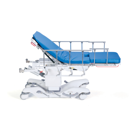
Mobile surgery platform
Inhaltsverzeichnis
Verfügbare Sprachen
Verfügbare Sprachen
Quicklinks
O p e r a t i o n sMa n u a l
O p é r a t i o n sMa n u e l l e s
B e t r i e b eMa n u e l l
H e t H a n d b o e kv a nv e r r i c h t i n g e n
F u n z i o n a me n t i Ma n u a l i
O p e r a c i o n e sMa n u a l e s
O p e r a ç õ e sMa n u a i s
O p e r a ç õ e sMa n u a i s
Me d i c a l
®
T r i o
Mo b i l eS u r g e r yP l a t f o r m
Mo d e l 1 0 3 3
Kapitel
Inhaltsverzeichnis

Verwandte Anleitungen für Stryker Trio 1033


Inhaltszusammenfassung für Stryker Trio 1033
- Seite 1 O p e r a t i o n sMa n u a l Me d i c a l O p é r a t i o n sMa n u e l l e s B e t r i e b eMa n u e l l H e t H a n d b o e kv a nv e r r i c h t i n g e n F u n z i o n a me n t i Ma n u a l i O p e r a c i o n e sMa n u a l e s...
- Seite 3 O p e r a t i o n sMa n u a l Me d i c a l O p é r a t i o n sMa n u e l l e s B e t r i e b eMa n u e l l H e t H a n d b o e kv a nv e r r i c h t i n g e n F u n z i o n a me n t i Ma n u a l i O p e r a c i o n e sMa n u a l e s...
- Seite 27 Notes 1−24...
- Seite 52 Inhaltsverzeichnis Einleitung Technische Daten ............... Definitionen Warnung/Vorsicht/Hinweis .
-
Seite 53: Einleitung
Seitenneigung + 15° bis – 15° Stryker behält sich das Recht vor, technische Daten ohne Bekanntgabe zu ändern. DEFINITION DER BEGRIFFE WARNUNG / VORSICHT / HINWEIS Die Begriffe WARNUNG, VORSICHT und HINWEIS haben eine bestimmte Bedeutung und sind genau zu beachten. - Seite 54 Einleitung Bevor Sie das Gerät anwenden, ist es wichtig, dass Sie alle Informationen dieser Bedienungsanleitung gele- sen und verstanden haben. Lesen Sie die Warnungen und Vorsichtsmaßnahmen auf dieser Seite aufmerk- sam durch und befolgen Sie diese. WARNUNG Wenn der Tisch während einer Behandlung oder Untersuchung oder während des Auf− und Absteigens be- wegt wird, können Verletzungen verursacht werden.
- Seite 55 Einleitung Zur Vermeidung von Beschädigungen räumen Sie alle hinderlichen Gegenstände beiseite, bevor Sie die Höhe oder Lage des Tisches verstellen. Wenn sich der Tisch in umgekehrter Trendelenburg−Lage befindet, und das Fußteil abgesenkt ist, kann dieses den Boden berühren. Um Beschädigungen des Gerätes zu vermeiden, heben Sie das Bett oder das Fußteil in die flache Lage, bevor Sie den Tisch in die umgekehrte Trendelenburg−Stellung bringen.
-
Seite 56: Betätigung Des Bremssystems
Betriebsanleitung BETÄTIGUNG DES BREMSSYSTEMS BREMS−/LENKPEDAL HINWEIS Zu beiden Seiten des Untergestelles sind Brems− und Lenkpedale angebracht, um das Fahren des Tisches zu erleichtern. S Zum Anziehen der Bremsen treten Sie die mit dem roten Etikett gekennzeichnete Seite des Pedals her- unter. -
Seite 57: Betätigung Des Lenksystems
Betriebsanleitung BETÄTIGUNG DES LENKSYSTEMS BREMS−/LENKPEDAL HINWEIS Zu beiden Seiten des Untergestelles sind Brems− und Lenkpedale angebracht, um das Fahren des Tisches zu erleichtern. Unter der Bodenplatte in der Mitte des Untergestelles befindet sich ein einziehbares Lenkrad (schwenkbar), das beim Transport eines Patienten die Manövrierfähigkeit des Operationstisches sowohl bei der Geradeaus- fahrt als auch beim Abbiegen erleichtert. -
Seite 58: Verstellen Der Betthöhe
Betriebsanleitung VERSTELLEN DER BETTHÖHE S Zum Anheben des Bettes treten Sie auf das „Up“−Pedal (A) und lassen es wieder los. Wiederholen Sie diesen Vorgang, bis die gewünschte Höhe erreicht ist. S Zum Absenken des Bettes treten Sie auf das „Down“−Pedal (B) und halten Sie dieses unten, bis die gewünschte Höhe erreicht ist. -
Seite 59: Verstellen Der Rückenlehne
Betriebsanleitung VERSTELLEN DER RÜCKENLEHNE VERSTELLBÜGEL RÜCKENLEHNE S Zum Anheben der Rückenlehne auf die gewünschte Höhe drücken Sie den roten Bügel unter der Rückenlehne zum Auslösen der pneumatischen Betätigungshilfe. Nehmen Sie Ihre Hand (Hände) vom Bügel, wenn Sie die gewünschte Höhe erreicht haben. S Zum Absenken der Rückenlehne drücken Sie den roten Bügel sowie den Rückenlehnenrahmen nach unten bis die Rückenlehne die gewünschte Höhe erreicht hat. -
Seite 60: Fußteil
Betriebsanleitung FUSSTEIL VERSTELLBÜGEL FUSSTEIL S Zum Absenken des Fußteiles drücken Sie mit einer Hand auf den Bügel an der Seite des Fußendes des Bettes. Drücken Sie gleichzeitig das Fußteil nach unten, bis der gewünschte Winkel erreicht ist. S Zum Anheben des Fußteiles drücken Sie mit einer Hand auf den Bügel an der Seite des Fußendes und halten Sie dieses mit der anderen Hand fest, damit es sich nicht zu schnell hebt. - Seite 61 Betriebsanleitung FUSSTEIL (FORTSETZUNG) GRIFFE ZUM ABNEHMEN DES FUSSTEILES S Zum Abnehmen des Fußteiles für Behandlungsmaßnahmen im Becken− und Unterkörperbereich drücken Sie auf die Griffe, die zu beiden Seiten des Fußteiles angebracht sind, und ziehen Sie das Fußteil aus den beiden Aufnahmen heraus. S Zum Ansetzen des Fußteiles neigen Sie dieses und stecken dessen beide Arme in die Aufnahmen am Bettgestell.
-
Seite 62: Trendelenburg−/Umgekehrte Trendelenburg−Lage
Betriebsanleitung TRENDELENBURG−/UMGEKEHRTE TRENDELENBURG−LAGE WARNUNG Um zu verhindern, dass der Patient fällt und sich verletzt, gurten Sie diesen immer an, wenn Sie das Bett des Operationstisches in Trendelenburg− / umgekehrte Trendeleburg−Lage bringen. S Zur Einstellung der Trendelenburg−Lage (Kopf nach unten) drehen Sie die Handkurbel (A) am Kop- fende des Gerätes im Uhrzeigersinn. -
Seite 63: Geneigte Seitenlage
Betriebsanleitung GENEIGTE SEITENLAGE KURBEL FÜR DIE GENEIGTE SEITENLAGE VORSICHT Zur Vermeidung von Beschädigungen räumen Sie alle hinderlichen Gegenstände beiseite, bevor Sie die Höhe oder Lage des Tisches verstellen. S Zur Einstellung der positiven Seitenneigung (linke Seite oben) drehen Sie die Kurbel am Kopfende des Tisches im Uhrzeigersinn. -
Seite 64: Seitengeländer
Betriebsanleitung SEITENGELÄNDER VON BETT UND FUSSTEIL S Zum Anheben der Seitengeländer des Bettes ziehen Sie die obere Stange (A) des Bettgeländers in die oberste Stellung, bis die Klinke mit einem hörbaren Klicken eingerastet ist. S Zum Absenken der Seitengeländer des Bettes drücken Sie die rote Klinke (B) am Bett und drücken Sie das Geländer nach unten in seine eingeklappte Stellung. -
Seite 65: Aufnahmestangen Für Chirurgische Instrumente
Betriebsanleitung AUFNAHMESTANGEN FÜR CHIRURGISCHE INSTRUMENTE ZUBEHÖRAUFNAHMESTANGE ZUBEHÖRAUFNAHMESTANGE ZUBEHÖRAUFNAHMESTANGE S Stangen zur Aufnahme von Zubehör umranden den Bettkasten, an denen Klammern und sonstige chirur- gische Hilfsmittel befestigt werden können. WARNUNG Zur Vermeidung von Verletzungen des Patienten oder Beschädigungen des Gerätes entfernen Sie alle Instrumente von der Zubehörstange des Fußteiles, bevor Sie die Stellung des Fußteiles ändern, und von der Zubehörstange der Rückenlehne, bevor Sie deren Stellung ändern. -
Seite 66: Aufnahmen Der Infusionsständer
Betriebsanleitung AUFNAHMEN DER INFUSIONSSTÄNDER STÄNDERAUFNAHME AM KOPFENDE (1 VON 2) STÄNDERAUFNAHME AM FUSSENDE (1 VON 2) S Zwei Aufnahmen für Standard−Infusionsständer sind jeweils am Kopfende des Tisches an der Rücken- lehne und am Fußende am Fußteil angebracht. WARNUNG Zur Vermeidung von Verletzungen des Patienten und Beschädigungen des Gerätes nehmen Sie die Infu- sionsständer aus den Aufnahmen am Fußende, bevor Sie dieses absenken. -
Seite 67: Bedienung Der Optionalen Fussseitigen Rückenstütze
Betriebsanleitung BEDIENUNG DER OPTIONALEN FUSSSEITIGEN RÜCKENSTÜTZE HINWEIS Um Probleme beim Ein− und Ausbau zu vermeiden, halten Sie die Fußseitige Rückenstütze waagerecht, während Sie die Führungsstäbe in die Buchsen schieben oder herausziehen. Zum Einbau der optionalen Fußseitigen Rückenstütze führen Sie die beiden Führungsstäbe (A) in die Buch- sen am Fußende der Bahre ein. -
Seite 68: Bedienung Des Gelenkkopfteils Der Optionalen Fussseitigen Rückenstütze
Betriebsanleitung BEDIENUNG DES GELENKKOPFTEILS DER OPTIONALEN FUSSSEITIGEN RÜCKENSTÜTZE Fußseitige Rückenstütze Kopfteil ACHSE ACHSE UNTERANSICHT Um das Gelenkkopfteil zu bedienen, ergreifen und pressen Sie einen der Hebel unter dem Kopfbereich. He- bel (A) löst einen Schnäpper und rotiert das Kopfteil auf Achse ”A”. Hebel (B) löst den anderen Schnäpper und rotiert das Kopfteil auf Achse ”B”. -
Seite 69: Bedienung Der Pre−Op/Post−Op Kopfverlängerungen Der Optionalen Fussseitigen Rückenstütze
Betriebsanleitung BEDIENUNG DER PRE−OP/POST−OP KOPFVERLÄNGERUNGEN DER OPTIONALEN FUSSSEITIGEN RÜCKENSTÜTZE UNTERANSICHT Die Pre−Op/Post−Op−Kopfverlängerungen dürfen nur in Verbindung mit dem Gelenkkopfteil der Fußseitigen Rückenstütze benutzt werden, um zusätzliche Liegefläche zu verschaffen und den Kopf des Patienten wäh- rend des Transports zu schützen. Die Kopfverlängerungen können als Handgriff zum Schieben des Trio be- nutzt werden. -
Seite 70: Bedienung Der Aufsteckbaren Seitenschienen Der Optionalen Fussseitigen Rückenstütze
Betriebsanleitung BEDIENUNG DER AUFSTECKBAREN SEITENSCHIENEN DER OPTIONALEN FUSSSEITIGEN RÜCKENSTÜTZE LINKS RECHTS WARNUNG Die aufsteckbaren Seitenschienen dürfen nur in Verbindung mit der Fußseitigen Rückenstütze verwendet werden. Montieren Sie die aufsteckbaren Seitenschienen ausschließlich auf die Zubehörschienen der Fuß- seitigen Rückenstütze. Verwenden Sie die aufsteckbaren Seitenschienen nicht in Verbindung mit Standard− Fußbereichen, da sie dort nicht sicher befestigt werden können, was zu Verletzungen führen kann. -
Seite 71: Bedienung Der Optionalen Cysto−Pfanne
Betriebsanleitung BEDIENUNG DER OPTIONALEN CYSTO−PFANNE Kippen Sie den Halter der Cysto−Pfanne (A) und schieben sie ihn zwischen die oberen und unteren Rollen auf die Bah- renträger. Platzieren Sie die Cysto−Pfanne (B) auf den Halteträger. Der Träger und die Pfanne lassen sich un- ter die Bahre schieben. -
Seite 72: Vorbeugende Wartung
HINWEIS Vorbeugende Wartungsmaßnahmen sind mindestens einmal pro Jahr durchzuführen. Ein Programm zur vor- beugenden Wartung ist für alle Geräte von Stryker Medical zu erstellen. Je nach dem Abnutzungsgrad der Produkte kann es sich als notwendig erweisen, vorbeugende Wartungsmaßnahmen öfter durchzuführen. -
Seite 73: Reinigung
Diese Produkte sind ätzend und können bei unsachgemäßem Gebrauch die Gurte beschädigen. Werden diese Produkte zur Reinigung von Stryker−Geräten verwendet, ist sicherzustellen, dass die Geräte mit klarem Wasser gespült werden und nach der Reinigung richtig trocknen. Werden Die Geräte nicht richtig gespült und getrocknet, bleiben ätzende Reste auf der Oberfläche des Gerätes hängen,... -
Seite 74: Herstellergarantie
Rahmen und die Schweißstellen frei von strukturellen Defekten sind, solange sich das Bett im Besitz des Erstkäufers befindet. Auf Anfrage von Stryker müssen Produkte oder Teile, für die eine Garantie beansprucht wird, auf eigene Kosten an die Stryker−Niederlassung zurückgeschickt werden. Durch jedweden Missbrauch des Produkts oder Veränderung oder Reparatur durch andere, die nach Strykers Ermessen das Produkt... - Seite 75 Rückgabeberechtigung: Artikel können nur nach Genehmigung durch den Stryker−Kundendienst zurückgegeben werden. Es wird eine RMA−Nummer vergeben, die auf dem zurückgesandten Artikel vermerkt werden muss. Stryker behält sich das Recht vor, ein Versand− und Reinventarisierungsentgelt für zurückgegebene Artikel zu verlangen. SPEZIELLE, MODIFIZIERTE ODER NICHT MEHR GEFÜHRTE ARTIKEL KÖNNEN NICHT...
- Seite 123 Note 5−24...
- Seite 147 Notas 6−24...