
Verwandte Anleitungen für Mettler Toledo xpress XTC


Inhaltszusammenfassung für Mettler Toledo xpress XTC
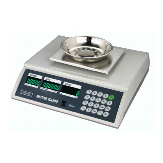
- Seite 1 STANDARD COUNTING SCALE OPERATION & SERVICE MANUAL Model XTC STANDARD COUNTING SCALE www.mt.com/xpress...
- Seite 2 All of our equipment is assembled and packed with great care. If you should find any incorrect item, please contact your Xpress Dealer immediately. This MT Xpress product was developed, produced, and tested in a METTLER TOLEDO facility that has been audited and registered according to international ISO 9001 quality standards and ISO 14000 environment control program.
- Seite 3 STANDARD COUNTING SCALE FCC Approval This device complies with part 15 of the FCC Rules. Operation is subject to the following two conditions: (1) this device may not cause harmful interference, and (2) this device must accept any interference received, including interference that may cause undesired operation.
-
Seite 4: Inhaltsverzeichnis
STANDARD COUNTING SCALE CONTENTS SAFTEY NOTICE............................5 PREPARING THE SCALE FOR USE ......................6 ENVIRONMENT ........................6 UNPACKING AND ASSEMBLY ....................6 YOUR XPRESS SCALE AT A GLANCE ......................8 DISPLAY ..........................8 KEYPAD..........................8 DISPLAY WINDOWS ........................8 CURSORS (VFD) ........................9 OPERATING YOUR SCALE ........................10 STRAIGHT COUNTING ......................10 PUSH-BUTTON TARE ......................10 KEYBOARD TARE ........................11... -
Seite 5: Saftey Notice
STANDARD COUNTING SCALE SAFTEY NOTICE Product safety is a fundamental concern at MT Xpress. Use common sense and follow the simple precautions listed below to ensure your safety and to optimize the use and performance of this product. − Read this manual before operating or servicing this product. Save this manual for future reference. −... -
Seite 6: Preparing The Scale For Use
STANDARD COUNTING SCALE PREPARING THE SCALE FOR USE The XTC Standard Counting Scale is a high performance industrial counting scale that accurately and dependably counts parts of all shapes and sizes. This manual provides not only the detailed information on how to operate the scale, but also useful messages for service and maintenance. - Seite 7 STANDARD COUNTING SCALE 5 lb models 10/20/50 lb models (20/50 lb models skip this step) All models Level the scale by adjusting the four rubber feet Proper alignment Improper alignment until the leveling bubble is centered in the level indicator.
-
Seite 8: Your Xpress Scale At A Glance
STANDARD COUNTING SCALE YOUR XPRESS SCALE AT A GLANCE DISPLAY KEYPAD Name Function Numeric Data entry (0-9) Decimal Enters a decimal point/Toggles alarm beep Zero Zeroes the scale Tare Subtracts tare value and switches from gross to net mode Clear Clears data from the display Initiates Average Piece Weight (APW) entry Sample... -
Seite 9: Cursors (Vfd)
STANDARD COUNTING SCALE CURSORS (VFD) Description →0← When the scale is at the gross zero, this cursor will be lit lb, kg, g Weight unit cursor; Weight unit can be set in Setup Mode When net weight is displayed, this cursor will be lit When item number is recalled, this cursor will be lit When Average Piece Weight (APW) is recalled, this cursor will be lit When gross weight is recalled, this cursor will be lit... -
Seite 10: Operating Your Scale
STANDARD COUNTING SCALE OPERATING YOUR SCALE STRAIGHT COUNTING The XTC counting scale is in the weight mode and ready for Weight Data Count 0 0 0 0 counting operation. >0< < > Place the samples on the platter (e.g. 10 pieces, total weight Weight Data Count... -
Seite 11: Keyboard Tare
STANDARD COUNTING SCALE KEYBOARD TARE There are two operation procedures for this function. Operation Procedure 1 Weight Data Count Press the appropriate keys for the known tare value (e.g. 0.1 0 0 0 0 lb, press the keys to input tare value 0.1). >0<... -
Seite 12: Decrement Counting
STANDARD COUNTING SCALE DECREMENT COUNTING There are two decrement counting modes. Mode 1 Place the items to be counted in the container or on the Weight Data Count wrapping material and then onto the platter (e.g. 3 lb 0 0 0 0 including tare). -
Seite 13: Special Operation Functions
STANDARD COUNTING SCALE SPECIAL OPERATION FUNCTIONS ID FUNCTION 20 ID can be stored with 2-digit ID No. and APW and 6-digit item No. and tare. ID data will not be lost when power is off. Emptying the item No. can clear an ID. The tare stored in the ID is keyboard tare. Store an ID In the count or weight mode, press the key to enter the... -
Seite 14: Accumulation Function
STANDARD COUNTING SCALE ACCUMULATION FUNCTION There are 21 accumulators to store the total counts. The data in the accumulator will be lost when power to the scale is lost. When the scale is in the count mode and the count is not Weight Data Count... -
Seite 15: Communication Function
STANDARD COUNTING SCALE COMMUNICATION FUNCTION With the optional RS-232 cable kit, the XTC can communicate to a printer or a PC. DATA OUTPUT In accumulation display mode, press to print the total Weight Data Count counts and CN or transmit the data to a PC. t o t A L C n 4 5 0 0 >0<... -
Seite 16: Recall Function
STANDARD COUNTING SCALE RECALL FUNCTION The XTC can subtract some data via the key . The default data is APW when the scale powers up. The scale is in the count or weight mode. (Weight window Weight Data Count 3 0 0 0 00 0 2 0 0 1 5 0 0 shows the weight value.) <... -
Seite 17: Apw Enhancement
STANDARD COUNTING SCALE APW ENHANCEMENT APW enhancement improves the accuracy of an APW. APW enhancement is based on the fact that an inaccurate APW, while not able to accurately count large numbers of parts, will reliably count a small number. This allows a determination of APW based on a larger weight. Given enough enhancements, the APW becomes very accurate. -
Seite 18: Special Modes - Setup Mode
STANDARD COUNTING SCALE SPECIAL MODES – SETUP MODE ENTERING THE SETUP MODE The operating parameters can be configured in the Setup Mode. When “Full Operator Access” is enabled in the Service Mode, step S3.1, the Setup Mode can be accessed by pressing and holding the key for about seven seconds and then releasing the key. -
Seite 19: Display Illustration
STANDARD COUNTING SCALE DISPLAY ILLUSTRATION The scale automatically moves to the first block as soon as the master mode is accessed. Press the key to toggle among blocks [SCALE], [tArE], [SAMPLE], [dAtA], [SEriAL], [id] and [End]. When a block is displayed, press the key to access the first sub-block or to go to end block. - Seite 20 STANDARD COUNTING SCALE F3.3 Auto Clear Tare Off =Disable auto clear tare On = Enable auto clear tare Automatic clear of tare occurs when net weight exceeds 9d. It settles to no motion and then returns to within +/-3d from gross zero. Sample Block F4.1 Minimum Sample Off = No minimum sample weight is required.
- Seite 21 STANDARD COUNTING SCALE Block 300 = 300 baud 1200 = 1200 baud 2400 = 2400 baud 4800 = 4800 baud 9600 = 9600 baud F6.2 Print Line Format Off = Multiple line format On = Single line format F6.3 Print ID Off = Disable printing of ID On = Enable printing of ID F6.4 Print Gross...
- Seite 22 STANDARD COUNTING SCALE Off = Disable ID On = Enable ID F7.2 Auto Clear ID Off = Disable auto clear ID On = Enable auto clear ID End Block This block is used to exit the Setup Mode. After exiting the Setup Mode, the scale will self-test automatically and enter into weight mode.
-
Seite 23: Cleaning And Maintaining Your Scale
STANDARD COUNTING SCALE CLEANING AND MAINTAINING YOUR SCALE WARNING DISCONNECT ALL POWER TO THIS UNIT BEFORE INSTALLING, SERVICING, CLEANING, OR REMOVING THE FUSE. FAILURE TO DO SO COULD RESULT IN BODILY HARM AND/OR PROPERTY DAMAGE. CLEANING AND MAINTENANCE − DO NOT allow untrained personnel to operate, clean, inspect, maintain, service, or tamper with this equipment. -
Seite 24: Servicing Your Scale
STANDARD COUNTING SCALE SERVICING YOUR SCALE For the following services, please contact your Xpress representative at www.mt.com/xpress. WARNING DISCONNECT ALL POWER TO THIS UNIT BEFORE INSTALLING, SERVICING, CLEANING, OR REMOVING THE FUSE. FAILURE TO DO SO COULD RESULT IN BODILY HARM AND/OR PROPERTY DAMAGE. CAUTION BEFORE CONNECTING OR DISCONNECTING ANY INTERNAL ELECTRONIC COMPONENTS OR INTERCONNECTING WIRING BETWEEN ELECTRONIC EQUIPMENT, ALWAYS REMOVE POWER AND... -
Seite 25: Configuration
STANDARD COUNTING SCALE The following diagram gives an overview of the program blocks and sub-blocks. Service Mode Test Block End Block Control Block Calibration Block Operator Access Save/Abort Expended Weight CAL Units Country GEO Code Capacity Increment Linearity Calibration Once the Service Mode is accessed, the scale directly prompts to the first block. Press the key toggle among blocks [tESt], [CALIbr], [COntrL] and [End].Service Mode sample display - Test block Weight Data... - Seite 26 STANDARD COUNTING SCALE S2.2 GEO Code GEO. = xx Select the GEO code according to your location. Please refer to Appendix for your local GEO code. The scale has been calibrated at the factory. In most cases, the scale doesn't have to be recalibrated. If the scale is found out of tolerance after GEO code adjustment, perform the calibration.
- Seite 27 STANDARD COUNTING SCALE Press the key , the scale will start capturing span and counting down from 5 to 0. Then scale will automatically step forward to the next block. If “yes” in S2.5 is chosen, the scale needs two points for calibrating the scale. The procedure to add weight will be as follows (take 5lb scale as example): After capturing the zero, it will show: Weight...
-
Seite 28: Communication
STANDARD COUNTING SCALE Control Block S3.1 Operator Access to Master Mode Off = No access is allowed to Setup Mode by pressing the key On = Full access is allowed to Setup Mode when the key is pressed and held for about 7 seconds Enable tare S3.2 Country 2 = Export version 3 = China version... - Seite 29 STANDARD COUNTING SCALE Single Line Output The following is the outputted contents and the related format. Format CN: Add one after each printing operation. SP SP Item No. Gross weight Tare weight Net weight Average piece weight (APW) Pieces CR LF Note: •...
- Seite 30 STANDARD COUNTING SCALE Average piece weight X SP b SP A P W CR LF Pieces X SP S CR LF Notice: The actual weight unit printed depends on the softswitch setting of Power- up Weight Unit. When the weight unit is g, the APW should be: X SP g SP A P W CR LF...
-
Seite 31: Appendix
STANDARD COUNTING SCALE APPENDIX SETUP MODE PARAMETER OVERVIEW Block Soft Switch Description Default User Block F1.1 Beeper Scale Block F2.1 Power-up Weight Unit F2.3 Digital Filter F2.4 Blank Count Display F2.5 Displayed Resolution Choice Tare Block F3.1 Tare F3.2 Keyboard Tare F3.3 Auto Clear Tare Sample Block... -
Seite 32: Error Messages
STANDARD COUNTING SCALE ERROR MESSAGES The scale will display an error message if a problem or an incorrect keyboard entry is sensed. The error codes are: Display Possible Cause Troubleshooting RAM error 1. Restart the scale. 2. Recalibrate the scale. 3. -
Seite 33: Specifications
STANDARD COUNTING SCALE SPECIFICATIONS Display Units 3 part display (5 digit Weight, 6 digit Data, 6 digit lb, kg, g Count) Interface 12 mm height, green VFD RS232 (Accessory) Internal Resolution Power 1/500,000 External adapter 12V/600mA Displayed Resolution Recommended APW Default: 1/10’000 >1/5d (0.2d) -
Seite 34: Geo Value Table
STANDARD COUNTING SCALE GEO VALUE TABLE Use the following geo codes if you relocate your scale to a site other than the original location where it was calibrated. Northern Height above sea-level in meters 1300 1625 1950 2275 2600 2925 3250 Southern 1300... -
Seite 35: Physical Dimensions
STANDARD COUNTING SCALE PHYSICAL DIMENSIONS Weight Data Count XTC-1001 Weight Data Count XTC-2001, XTC-3001, XTC-4001... - Seite 36 STANDARD COUNTING SCALE Notes...
- Seite 37 STANDARD COUNTING SCALE Notes...
- Seite 38 Xpress Mettler-Toledo, Inc. 60 Collegeview Westerville, OH 43081 5/2004 MTX04-OM007.1E STANDARD COUNTING SCALE www.mt.com/xpress...
- Seite 39 THERMAL PRINTER TSP600 SERIES USER’S MANUAL MODE D’EMPLOI BEDIENUNGSANLEITUNG MANUALE DI ISTRUZIONI...
- Seite 40 Federal Communications Commission Radio Frequency Interference Statement This equipment has been tested and found to comply with the limits for a Class A digital device, pursuant to Part 15 of the FCC Rules. These limits are designed to provide reasonable protection against harmful interference when the equipment is operated in a commercial environment.
- Seite 41 TABLE OF CONTENTS 1. Parts Identification and Nomenclature ............1 2. Consumable Parts and AC Adapter ..............4 3. Connecting Cables and AC Adapter ..............6 3-1. Interface Cable ..................6 3-2. Connecting to a Peripheral Unit ............. 8 3-3. Connecting the Optional AC Adapter ............9 3-4.
-
Seite 42: Parts Identification And Nomenclature
1. Parts Identification and Nomenclature Auto Cutter Model Printer cover Open this cover to load or replace paper. Cover open lever Pull this lever in the direction of the arrow to open the printer cover. Power switch Used to turn on/off Control panel power to the printer. -
Seite 43: Tear Bar Model
Tear Bar Model Printer cover Open this cover to load or replace paper. Cover open lever Pull this lever in the direction of the arrow to open the printer cover. Power switch Used to turn on/off Control panel power to the printer. Features LED indica- tors to indicate printer status and switches to... -
Seite 44: Choosing A Place For The Printer
Choosing a place for the printer Before actually unpacking the printer, you should take a few minutes to think about where you plan to use it. Remember the following points when doing this. Choose a firm, level surface where the printer will not be exposed to vibration. -
Seite 45: Consumable Parts And Ac Adapter
2. Consumable Parts and AC Adapter When consumable parts have run out, use those specified in the table below. Make sure that the AC adapter specified in the table is used. Use of consumable parts or AC adapter which are not specified in the table may result in damage to the printer, fire or electric shock. - Seite 46 (3) AC adapter (option) Model name: PS60-24 A Input: 100 to 240 V AC, 50/60 Hz Output: DC24±5%, 2.0 A (5.0 A Load 10 sec. Max) Important! Access the following URL for the information of the recommended paper. http://www.star-micronics.co.jp/ – 5 –...
-
Seite 47: Connecting Cables And Ac Adapter
3. Connecting Cables and AC Adapter 3-1. Interface Cable 3-1-1. Ferrite Core Installation (Parallel interface model only) (1) For only the parallel interface model, affix the ferrite core onto the cable as shown in the illustration below. Ferrite core Interface cable (2) Pass the fastener through the ferrite 5 cm maximum... -
Seite 48: Connecting The Interface Cable
3-1-2. Connecting the Interface Cable Note: Before connecting/disconnecting the interface cable, make sure that power to the printer and all the devices connected to the printer is turned off. Also make sure the power cable plug is disconnected from the AC outlet. -
Seite 49: Connecting To A Peripheral Unit
3-2. Connecting to a Peripheral Unit You can connect a peripheral unit to the printer using a modular plug. The following describes how to install the ferrite core and make the actual connection. See “Modular plug” on page 108 for details about the type of modular plug that is required. -
Seite 50: Connecting The Optional Ac Adapter
3-3. Connecting the Optional AC Adapter Note: Before connecting/disconnecting the AC adapter, make sure that power to the printer and all the devices connected to the printer is turned off. Also make sure the power cable plug is disconnected from the AC outlet. -
Seite 51: Turning Power On
3-4. Turning Power On Make sure that the AC adapter has been connected as described in 3-3. (1) Set the power switch located on the front of the printer to on. The POWER lamp on the control panel will light up. Power switch Important! We recommend that you unplug the printer from the power outlet... -
Seite 52: Control Panel And Other Functions
4. Control Panel and Other Functions 4-1. Control Panel 1 POWER lamp (Green LED) Lights when the power is ON 2 ERROR lamp (Red LED) Indicates various errors in combi- nation with POWER lamp 3 FEED button Press the FEED button to feed roll 3 FEED button paper. - Seite 53 3) Paper cut error ERROR lamp Error Description POWER lamp Recovery Conditions Flashes at 0.125 Paper cut error Recovered If the cutter returns to the second intervals home position after turning the power OFF and ON. Restoration is also possible with the <DLE><ENQ>n command when in the ESC/POS mode.
-
Seite 54: Self Printing
4-3. Self Printing (1) Test Printing Turn the power on while holding the FEED button depressed. Test printing will be performed according to the Ver. No., DIP switch settings and character order. When the FEED button is depressed at the time of the end of test printing, only the characters will be printed out repeatedly. -
Seite 55: Loading The Roll Paper
5. Loading the Roll Paper Be sure to use roll paper that matches the printer’s specification. When using a paper roll with an 57.5 mm width, install the optional paper roll holder as described on the following page. 1) Push the Cover open lever, and open the printer cover. - Seite 56 Paper roll holder Note: When using a paper roll with an 57.5 mm width, install the optional paper roll holder in the groove in the printer. 3) Push down both sides of the printer cover to close. Note: Make sure that the printer cover is securely closed.
- Seite 57 Important! 1. Do not touch the cutter blade. · There is a cutter inside the paper outlet slot. Not only should you not put your hand in the paper outlet slot while printing is in progress, never put your hand into the outlet even when printing is not in progress.
-
Seite 58: Adjusting The Near-End Sensor
6. Adjusting the Near-end Sensor Use the following procedure to adjust the near-end sensor so it is compatible with the size of roll paper you are using. 1 Open the printer cover. 2 Determine the diameter of the roll paper you are using and find the required setting in the table below. - Seite 59 Adjustment value according to the paper you are using Paper thick- When using the paper roll with a core whose inside diameter (A):ø12, outside diameter ness ( µ m) (B):ø18 Detected diameter (C) Remained paper length (Approx. mm) (Approx. m) Level 1 Level 2 Level 1...
-
Seite 60: Preventing And Clearing Paper Jams
7. Preventing and Clearing Paper Jams 7-1. Preventing Paper Jams The paper should not be touched during ejection and before it is cut. Pressing or pulling the paper during ejection may cause a paper jam, paper cutting failure or line feed failure. 7-2. -
Seite 61: Releasing A Locked Cutter (Auto Cutter Mode Only)
7-3. Releasing a Locked Cutter (Auto Cutter Mode only) If the auto cutter locks up or fails to cut the paper, follow the steps below. Caution Since working on the cutter may be dangerous, be sure to turn off the printer first. (1) Set the power switch to OFF to turn off the printer. - Seite 62 (4) If the cutter’s moving blade is protruding, use a Phillips screwdriver to turn the Phillip-head screw and return the moving blade to its home position. When the check window is completely white, the moving blade is at its home position.
-
Seite 63: Periodical Cleaning
8. Periodical Cleaning Printed characters may become partially unclear due to accumulated paper dust and dirt. To prevent such a problem, paper dust collected in the paper holder and paper transport section and on the surface of the thermal head must be removed periodically. - Seite 65 TABLE DES MATIERES 1. Identification des pièces et nomenclature ............ 25 2. Consommables et adaptateur secteur ............28 3. Câbles de connexion et adaptateur secteur ..........30 3-1. Câble d’interface .................. 30 3-2. Raccordement d’un appareil périphérique ........... 32 3-3. Connexion de l’adaptateur secteur optionnel ........33 3-4.
-
Seite 66: Identification Des Pièces Et Nomenclature
1. Identification des pièces et nomenclature Modèle avec coupe-papier automatique Capot de l’imprimante Ouvrez ce capot pour charger ou remplacer le papier. Levier d’ouverture du capot Tirez ce levier dans le sens de la flèche pour ouvrir le capot de l’imprimante. Interrupteur d’alimentation Permet la mise sous et Panneau des commandes... - Seite 67 Modèle avec barre de tension Capot de l’imprimante Ouvrez ce capot pour charger ou remplacer le papier. Levier d’ouverture du capot Tirez ce levier dans le sens de la flèche pour ouvrir le capot de l’imprimante. Interrupteur d’alimentation Permet la mise sous et Panneau des commandes hors tension de l’appareil.
-
Seite 68: Emplacement De L'imprimante
Emplacement de l’imprimante Avant de déballer l’imprimante, déterminez l’emplacement où vous souhaitez l’installer. Veuillez observer les points ci-dessous lors de votre choix. Choisissez une surface stable et de niveau sur laquelle l’imprimante ne sera exposée à aucune vibration. Assurez-vous que l’emplacement dispose d’une prise secteur proche et d’accès aisé. -
Seite 69: Consommables Et Adaptateur Secteur
2. Consommables et adaptateur secteur Il convient d’utiliser exclusivement les types de papier figurant dans le tableau ci- dessous. Veillez également à utiliser l’adaptateur secteur qui figure dans le tableau. L’utilisation d’un type de papier et d’adaptateur ne figurant pas dans le tableau risque d’endommager l’imprimante, de causer un incendie ou une décharge électrique. - Seite 70 (3) Adaptateur secteur (option) Nom du modèle: PS60-24 A Entrée: CA100 à 240 V, 50/60 Hz Sortie: CC24±5%, 2,0 A (charge de 10 sec à 5,0 A max.) Attention! Pour obtenir des informations concernant le papier recommandé, con- sultez l’adresse URL suivante : http://www.star-micronics.co.jp/. –...
-
Seite 71: Câbles De Connexion Et Adaptateur Secteur
3. Câbles de connexion et adaptateur secteur 3-1. Câble d’interface 3-1-1. Installation du tore de ferrite (modèle avec interface parallèle seulement) (1) Modèle avec interface parallèle seu- lement: fixez la grande gaine en ferrite sur le câble comme illustré. Tore de ferrite Interface câble 5 cm maximum... -
Seite 72: Connexion Du Câble D'interface
3-1-2. Connexion du câble d’interface Remarque:Avant de connecter ou déconnecter le câble d’interface, veillez à ce que l’imprimante et tous les appareils qui y sont connectés soient hors tension. Veillez également à débrancher le câble d’alimentation de la prise secteur. (1) Connectez le câble d’interface à... -
Seite 73: Raccordement D'un Appareil Périphérique
3-2. Raccordement d’un appareil périphérique Vous pouvez raccorder un appareil périphérique à l’imprimante à l’aide d’une fiche modulaire. Nous expliquons ci-dessous comment installer le tore de ferrite et faire le raccordement proprement dit. Pour les détails sur le type de fiche modulaire à... -
Seite 74: Connexion De L'adaptateur Secteur Optionnel
3-3. Connexion de l’adaptateur secteur optionnel Remarque:Avant de connecter ou déconnecter l’adaptateur secteur, veillez à ce que l’imprimante et tous les appareils qui y sont connectés soient hors tension. Veillez également à débrancher le câble d’alimentation de la prise secteur. (1) Connectez l’adaptateur secteur au câble d’alimentation. -
Seite 75: Mise Sous Tension De L'imprimante
3-4. Mise sous tension de l’imprimante Assurez-vous d’avoir bien connecté l’adaptateur secteur comme décrit à la section 3-3. (1) Placez l’interrupteur d’alimentation, situé à l’avant de l’imprimante, sur la position sous tension. La DEL POWER s’allume au panneau des commandes. Interrupteur d’alimentation Attention! -
Seite 76: Panneau De Commande Et Autres Fonctions
4. Panneau de commande et autres fonctions 4-1. Panneau de commande 1 Témoin POWER (DEL verte) S’allume quand l’appareil est sous tension. 2 Témoin ERROR (DEL rouge) Indique des erreurs variées en com- binaison avec le témoin POWER. 3 Témoin FEED 3 Témoin FEED (avance de papier) 2 Témoin ERROR (erreur) - Seite 77 3) Erreur de découpe du papier Témoin ERROR Description de l’erreur Témoin POWER Conditions de récupération Récupération si l’unité de décou- Clignote à 0,125 Erreur de découpe Hors tension page revient dans sa position d’ori- seconde d’inter- du papier gine après la mise hors tension et valle sous tension.
-
Seite 78: Auto-Impression
4-3. Auto-impression (1) Essai d’impression Mettez l’appareil sous tension tout en maintenant la touche FEED enfoncée. L’essai d’impression sera effectué en fonction du numéro de version, des réglages du commutateur DIP et de l’ordre des caractères. Si vous appuyez sur la touche FEED à... -
Seite 79: Chargement Du Rouleau De Papier
5. Chargement du rouleau de papier Veillez à utiliser un rouleau de papier qui correspond aux spécifications de l’imprimante. Lors de l’utilisation d’un rouleau de papier de 57,5 mm de large, chargez le rouleau de papier comme indiqué à la page suivante. 1) Poussez le levier d’ouverture du ca- pot et ouvrez le capot de l’impri- mante. - Seite 80 Support du rouleau de papier Remarque: Lors de l’utilisation d’un rouleau de papier de 57,5 mm de large, installez le support de papier dans le logement prévu dans l’imprimante. 3) Poussez vers la bas les deux côtés du capot de l’imprimante pour le fermer.
- Seite 81 Attention! 1. Ne pas toucher la lame du coupe-ruban. · Une lame se trouve dans la fente de sortie de papier. Il est fortement déconseillé de mettre sa main dans la fente de sortie de papier non seulement pendant l’impression mais aussi en toute autre circons- tance, même quand l’impression n’est pas effectuée.
-
Seite 82: Réglage Du Capteur De Fin De Rouleau
6. Réglage du capteur de fin de rouleau Utilisez la procédure suivante pour régler le capteur de fin de rouleau conformé- ment à la taille du rouleau de papier utilisé. 1 Ouvrez le capot de l’imprimante. 2 Déterminez le diamètre du rouleau de papier utilisé et identifiez le réglage requis dans le tableau ci-dessous. - Seite 83 Valeur de réglage correspondant au papier utilisé. Épaisseur du Quand vous utilisez un rouleau de papier dont le diamètre intérieur du support est de papier (µm) (A):ø12 et le diamètre extérieur de (B):ø18 Diamètre détecté (C) Longueur de papier restante (Env.
-
Seite 84: Prévention Et Correction De Bourrages De Papier
7. Prévention et correction de bourrages de papier 7-1. Prévention des bourrages de papier Il convient de ne jamais toucher le papier pendant son éjection et avant qu’il soit coupé. Appuyer ou tirer sur le papier pendant son éjection risque de provoquer un bourrage, des problèmes de coupure ou d’avance de ligne. -
Seite 85: Libération D'une Unité De Découpage Bloquée (Mode Coupe-Papier Automatique Uniquement)
7-3. Libération d’une unité de découpage bloquée (mode coupe-papier automatique uniquement) Si l’unité de découpage automatique se bloque ou ne coupe pas le papier, suivez les étapes ci-dessous. Attention Le travail sur l’unité de découpage étant dangereux, n’oubliez pas de mettre avant tout l’imprimante hors tension. - Seite 86 (4) Si la lame mobile de l’unité de découpage dépasse, utilisez un tournevis cruciforme pour tourner la vis cruciforme et ramener la lame dans sa position d’origine. Quand la fenêtre de contrôle est complètement blanche, la lame mobile est dans sa position d’origine. Remarque 1: N’appliquez pas de pression excessive sur la lame mobile.
-
Seite 87: Nettoyage
8. Nettoyage Les caractères imprimés pourraient devenir partiellement illisibles en raison de l’accumulation de la poussière de papier et de crasse. Afin de prévenir ce genre de problème, il convient de nettoyer régulièrement la poussière qui s’accumule sur le support de papier, les passages du papier et la surface de la tête d’impres- sion. - Seite 89 INHALTSVERZEICHNIS 1. Beschreibung und Bezeichnung der Geräteteile ......... 49 2. Verbrauchsteile und Netzteil ................ 52 3. Anschlußkabel und Netzteil ................54 3-1. Schnittstellenkabel ................54 3-2. Anschluß an ein Peripheriegerät ............56 3-3. Anschließen des optionalen Netzteils ..........57 3-4. Einschalten ................... 58 4.
-
Seite 90: Beschreibung Und Bezeichnung Der Geräteteile
1. Beschreibung und Bezeichnung der Geräteteile Auto-Schneidwerkmodell Abdeckung Diese Abdeckung öffnen, um Papier einzusetzen oder zu entnehmen. Abdeckung-öffnen-Hebel Diesen Hebel in Pfeilrichtung ziehen, um die Druckerabdeckung zu öffnen. Nur Parallel-Schnitt- schnelle-Modell Bedienfeld Zum Ein- oder Ausschal- Mit LED-Anzeigen ten des Druckers. zur Anzeige des Druckerstatus und Schalter zur... -
Seite 91: Abreißkantenmodell
Abreißkantenmodell Abdeckung Diese Abdeckung öffnen, um Papier einzusetzen oder zu entnehmen. Abdeckung-öffnen-Hebel Diesen Hebel in Pfeilrichtung ziehen, um die Druckerabdeckung zu öffnen. Nur Parallel-Schnitt- Bedienfeld schnelle-Modell Mit LED-Anzeigen Zum Ein- oder Ausschal- zur Anzeige des ten des Druckers. Druckerstatus und Schalter zur Druckerbedienung. -
Seite 92: Wahl Eines Aufstellungsorts Für Den Drucker
Wahl eines Aufstellungsorts für den Drucker Bevor Sie den Drucker auspacken, sollten Sie einige Minuten damit verbringen, einen geeigneten Aufstellungsort auszusuchen. Denken Sie dabei an die folgenden Punkte: Den Drucker auf einem flachen, aber festen Untergrund aufstellen, wo keine Vibrationen vorhanden sind. Die verwendete Steckdose soll in der Nähe und frei zugänglich sein. -
Seite 93: Verbrauchsteile Und Netzteil
2. Verbrauchsteile und Netzteil Wenn die Verbrauchsteile verbraucht sind, besorgen Sie Ersatz entsprechend der unten gezeigten Tabelle. Verwendung von Verbrauchsteilen oder Netzteilen, die nicht den unten aufge- führten Beschreibungen entsprechend, kann zu Schäden am Drucker, Bränden oder elektrischen Schlägen führen. (1) Rollenpapierbeschreibung Thermopapier Dicke: 65~85 µm... - Seite 94 Je nach Typ und Stärke des Papiers kann es erforderlich sein, die Einstellungen für die Druckintensität zu ändern. Zum Ändern der Intensitätseinstellung den Druckintensität-Befehle <ESC><RS>‘d’n verwenden. Einzelheiten siehe Programmieranleitung. (3) Netzteil (Option) Modelbezeichnung: PS60-24 A Eingang: 100 bis 240 V WS, 50/60 Hz Ausgang: 24 V GS±5%, max.
-
Seite 95: Anschlußkabel Und Netzteil
3. Anschlußkabel und Netzteil 3-1. Schnittstellenkabel 3-1-1. Anbringen des Ferritkerns (Nur beim Parallel-Schnittschnelle-Modell) (1) Nur beim Parallel-Schnittschnelle- Modell, Befestigen Sie den großen Ferritkern am Kabel, wie das in der folgenden Abbildung gezeigt wird. Ferritkern Kable Maximum 5 cm (2) Führen Sie den Kabelbinder durch den Ferritkern. -
Seite 96: Anschließen Des Schnittstellenkabels
3-1-2. Anschließen des Schnittstellenkabels Hinweis:Vor dem Anschließen/Abtrennen des Schnittstellenkabels stellen Sie sicher, daß der Drucker und alle angeschlossenen Gerät ausge- schaltet sind. Außerdem sollte der Netzstecker abgezogen sein. (1) Schließen Sie das Schnittstellenkabel an die Buchse an der Rückseite des Druckers an. -
Seite 97: Anschluß An Ein Peripheriegerät
3-2. Anschluß an ein Peripheriegerät Es kann ein Peripheriegerät an den Drucker mit einem Modularstecker ange- schlossen werden. Im folgenden wird beschrieben, wie der Ferritkern angebracht und die Verbindung hergestellt wird. Siehe “Modularstecker” auf Seite 108 für den Typ von Modularstecker, der dazu erforderlich ist. Beachten Sie, daß der Drucker nicht mit einem Modularstecker oder Kabel ausgestattet ist. -
Seite 98: Anschließen Des Optionalen Netzteils
3-3. Anschließen des optionalen Netzteils Hinweis:Vor dem Anschließen/Abtrennen des Netzteils stellen Sie sicher, daß der Drucker und alle angeschlossenen Gerät ausgeschaltet sind. Außerdem sollte der Netzstecker abgezogen sein. (1) Schließen Sie das Netzteil an das Netzkabel an. Hinweis:Verwenden Sie nur das vorgesehene Netzteil und Netzkabel. (2) Das Netzteil am Stecker des Druckers anschließen. -
Seite 99: Einschalten
3-4. Einschalten Stellen Sie sicher, daß das Netzteil angeschlossen ist, wie in 3-3 beschrieben. (1) Den Netzschalter vorne am Gerät auf Ein (ON) stellen. Das POWER- Lämpchen am Bedienfeld leuchtet auf. Netzschalter Wichtig! Wir empfehlen, den Netzstecker aus der Steckdose zu ziehen, wenn der Drucker längere Zeit lang nicht benutzt werden soll. -
Seite 100: Bedienfeld Und Andere Funktionen
4. Bedienfeld und andere Funktionen 4-1. Bedienfeld 1 POWER-Lämpchen (grüne LED) Leuchtet in eingeschaltetem Zustand 2 ERROR-Lämpchen (rote LED) Zeigt in Kombination mit dem PO- WER-Lämpchen verschiedene Fehlerzustände an 3 FEED-Taste 2 ERROR-Lämpchen 3 FEED-Taste (rote LED) Die FEED-Taste drücken, um das 1 POWER-Lämpchen Rollenpapier vorzutransportieren. -
Seite 101: Papiererkennung-Fehler
3) Papierschnitt-Fehler ERROR-Lämpchen Fehlerbeschreibung POWER-Lämpchen Behebungsbedingungen Blinkt im Abstand Papierschnitt-Feh- Behoben, wenn des Schneidwerk nach von 0,125 s dem Ein- und Ausschalten in Grund- stellung zurückkehrt. Wiederherstellung ist auch mit dem Befehl <DLE><ENQ>n möglich, wenn im ESC/POS-Modus. Hinweis 1) Wenn das Schneidwerk nicht in Grundstellung zurückkehrt oder nicht die Anfangsbewegung ausführt, ist Behebung nicht möglich. -
Seite 102: Selbstdruck
4-3. Selbstdruck (1) Testdruck Das Gerät einschalten, während die FEED-Taste gedrückt gehalten wird. Der Testdruck wird entsprechend der Ver. Nr., den DIP-Schalter-Einstellun- gen und der Zeichenfolge ausgeführt. Wenn die FEED-Taste beim Ende des Testdrucks gedrückt wird, werden nur die Zeichen wiederholt ausgedruckt. (2) Sedezimaler Datenausdruck Die Druckerabdeckung öffnen, und dann einschalten, während die FEED- Taste gedrückt gehalten wird. -
Seite 103: Einlegen Der Papierrolle
5. Einlegen der Papierrolle Immer Rollenpapier verwenden, das zu den technischen Daten des Druckers paßt. Bei Verwendung einer Papierrolle mit einer Breite von 57,5 mm den optionalen Papierrollenhalter wie auf der folgenden Seite beschrieben, einlegen. 1) Den Abdeckung-Öffnen-Hebel drücken, und die Druckerabdeckung öffnen. - Seite 104 Papierrollenhalter Hinweis 2: Bei Verwendung einer Pa- pierrolle mit einer Breite von 57,5 mm den optionalen Papierrollenhalter in die Rille im Drucker setzen. 3) Beide Seiten der Druckerabdeckung zum Schließen nach unten drücken. Hinweis: Sicherstellen, daß die Druckerabdeckung fest geschlossen ist.
- Seite 105 Wichtig! 1. Nicht die Schneidwerkklinge berühren. · Im Papierauslaßschlitz befindet sich ein Schneidwerk. Niemals die Hände in den Auslaßschlitz stecken, nicht nur während des Druck- betriebs sondern auch wenn der Drucker nicht arbeitet. · Die Druckerabdeckung kann geöffnet werden, wenn das Papier ausgetauscht wird.
-
Seite 106: Einstellung Des Endanäherungs-Sensors
6. Einstellung des Endanäherungs-Sensors Den Endanäherungs-Sensor auf folgende Weise justieren, damit er der Größe der verwendeten Papierrolle entspricht. 1 Die Druckerabdeckung öffnen. 2 Den Durchmesser der verwendeten Papierrolle ermitteln, und in der untenste- henden Tabelle die entsprechende Einstellung aufsuchen. 3 Die Spitze eines Kugelschreibers o.ä. Gegenstands in das Loch des Einstellers stecken, und dann eindrücken und den Einsteller auf die gewünschte Einstel- lung schieben. - Seite 107 Einstellwerte entsprechend des verwendeten Papiers Papierdicke Bei Verwendung einer Papierrolle mit einem Kern mit Innendurchmesser (A):ø12 und (µm) Außendurchmesser (B):ø18 Erkannter Durchmesser (C) Rest papier (Etwa mm) (Etwa m) Niveau 1 Niveaul 2 Niveau 1 Niveau 2 ø23 ø29 ø21 Hinweis 1) Das Standardmodell ist werkseitig auf Niveau 1 gestellt.
-
Seite 108: Verhindern Und Beheben Von Papierstau
7. Verhindern und Beheben von Papierstau 7-1. Verhindern von Papierstau Das Papier soll beim Ausgeben und vor dem Schneiden nicht berührt werden. Wenn das Papier beim Ausgeben gedrückt oder gezogen wird, kann ein Papiers- tau, ein Abschneidfehler oder ein Zeilenvorschubfehler verursacht werden. 7-2. -
Seite 109: Freigeben Eines Gesperrten Schneidmessers Nur Auto-Schneidwerkmodell
7-3. Freigeben eines gesperrten Schneidmessers Nur Auto- Schneidwerkmodell Wenn das automatische Schneidmesser sperrt oder das Papier nicht schneidet, wie folgt verfahren. Achtung: Da Arbeiten am Schneidmesser gefährlich sein können, immer zuerst den Drucker ausschalten. (1) Den Netzschalter auf Aus (OFF) stellen, um den Drucker auszuschalten. (2) Die Frontabdeckung abschieben, um das Schneidmesser freizulegen. - Seite 110 (4) Wenn die bewegliche Klinge des Schneidmessers hervorsteht, mit einem Kreuzschlitzschraubenzieher die Kreuzschlitzschraube drehen, und die be- wegliche Klinge in Grundstellung zurückstellen. Wenn das Prüffenster voll- ständig weiß ist, ist die bewegliche Klinge in Grundstellung. Hinweis 1: Nicht starken Druck auf die bewegliche Klinge ausüben. Hinweis 2: Wenn die bewegliche Klinge zu sehr hervorsteht, kann die Druckerabdeckung nicht geöffnet werden.
-
Seite 111: Regelmäßige Reinigung
8. Regelmäßige Reinigung Die Druckzeichen können durch Ansammlung von Papierstaub und anderem Schmutz unscharf werden. Um das zu verhindern, muß im Papierhalter und in der Papiertransportstufe angesammelter Staub von Zeit zu Zeit entfernt werden. Diese Reinigung sollte einmal alle sechs Monate oder einmal nach jeder Million Zeilen ausgeführt werden. - Seite 113 INDICE 1. Identificazione delle parti e nomenclatura ..........73 2. Parti soggette a consumo e trasformatore CA ..........76 3. Cavi di collegamento e trasformatore CA ........... 78 3-1. Cavo interfaccia ................... 78 3-2. Collegamento ad un’unità periferica ............ 80 3-3.
-
Seite 114: Identificazione Delle Parti E Nomenclatura
1. Identificazione delle parti e nomenclatura Modello con taglierina automatica Coperchio stampante Aprire questo coperchio per inserire o sostituire la carta. Leva di apertura coperchio Tirare questa leva in direzione della freccia per aprire il coperchio della stampante. Interruttore di alimentazione Pannello di controllo Usarlo per accen-... -
Seite 115: Modello Con Barra Di Strappo
Modello con barra di strappo Coperchio stampante Aprire questo coperchio per inserire o sostituire la carta. Leva di apertura coperchio Tirare questa leva in direzione della freccia per aprire il coperchio della stampante. Interruttore di alimentazione Pannello di controllo Usarlo per accen- Dispone di indicatori LED dere/spegnere la che indicano lo stato della... -
Seite 116: Scelta Di Un Luogo Per La Stampante
Scelta di un luogo per la stampante Prima di disimballare la stampante, decidere dove si desidera installarla. Tenere presenti i seguenti punti. Scegliere una superficie stabile e in piano, dove la stampante non sia esposta a vibrazioni. La presa di corrente che si intende usare per la stampante deve essere vicina e libera da ostacoli. -
Seite 117: Parti Soggette A Consumo E Trasformatore Ca
2. Parti soggette a consumo e trasformatore CA Quando le parti soggette a consumo si sono esaurite, usare quelle specificate nella seguente tabella. Assicurarsi di usare il trasformatore CA specificato nella tabella. L’uso di parti soggette a consumo o di un trasformatore CA diversi da quanto specificato nella tabella può... - Seite 118 (3) Trasformatore CA (opzionale) Nome modello: PS60-24 A Ingresso: Da 100 a 240 V CA, 50/60 Hz Uscita: 24±5%CC, 2,0 A (5,0 A carico 10 sec. mass.) Importante! Accedere alla seguente URL per informazioni sulla carta consigliata. http://www.star-micronics.co.jp/ – 77 –...
-
Seite 119: Cavi Di Collegamento E Trasformatore Ca
3. Cavi di collegamento e trasformatore CA 3-1. Cavo interfaccia 3-1-1. Installazione dell’anello di ferrite (solo modello a interfaccia parallelo) (1) Solo per il modello a interfaccia parallelo, fissare l’anello di ferrite al cavo come mostrato nell’illustra- zione qui sotto. Anello di ferrite Cavo 5 cm massimo... -
Seite 120: Collegamento Del Cavo Interfaccia
3-1-2. Collegamento del cavo interfaccia Nota: Prima di collegare/scollegare il cavo interfaccia, assicurarsi che la stampante e tutti i dispositivi collegati alla stampante siano spenti. Inoltre assicurarsi che la spina del cavo di alimentazione sia scollegata dalla presa di corrente. (1) Collegare il cavo interfaccia al connettore sul pannello posteriore della stampante. -
Seite 121: Collegamento Ad Un'unità Periferica
3-2. Collegamento ad un’unità periferica Si può collegare un’unità periferica alla stampante usando una spina modulare. Di seguito descriviamo come installare l’anello di ferrite ed eseguire il collega- mento. Vedere “Modulare necessario” a pagina 108 per dettagli sul tipo di spina modulare necessario. -
Seite 122: Collegamento Del Trasformatore Ca Opzionale
3-3. Collegamento del trasformatore CA opzionale Nota: Prima di collegare/scollegare il trasformatore CA, assicurarsi che la stampante e tutti i dispositivi collegati alla stampante siano spenti. Inoltre assicurarsi che la spina del cavo di alimentazione sia scollegata dalla presa di corrente. (1) Collegare il trasformatore CA al cavo di alimentazione. -
Seite 123: Accensione
3-4. Accensione Assicurarsi che il trasformatore CA sia stato collegato come indicato nella sezione 3-3. (1) Regolare su ON l’interruttore di alimentazione situato sul davanti della stampante. La spia POWER sul pannello di controllo si illumina. Interruttore di alimentazione Importante! Consigliamo di scollegare la stampante dalla presa di corrente quando si prevede di non usarla per un lungo periodo. -
Seite 124: Pannello Di Controllo E Altre Funzioni
4. Pannello di controllo e altre funzioni 4-1. Pannello di controllo 1 Spia POWER (LED verde) Si illumina quando l’unità è accesa. 2 Spia ERROR (LED rosso) Indica vari errori in combinazione con la spia POWER. 3 Tasto FEED 3 Tasto FEED Premere il tasto FEED per far avan- zare la carta su rotolo. - Seite 125 3) Errore di taglio carta Spia ERROR Descrizione dell’errore Spia POWER Condizioni di recupero Lampeggia a in- Errore di taglio carta Accesa Recupero se la taglierina ritorna tervalli di 0,125 alla posizione di riposo dopo che si secondi è spenta e riaccesa l’unità. Il ripristino è...
-
Seite 126: Stampa Automatica
4-3. Stampa automatica (1) Stampa di prova Accendere l’unità tenendo premuto il tasto FEED. La stampa di prova viene eseguita nell’ordine di numero di versione, impostazioni degli interruttori DIP e ordine dei caratteri. Se si preme il tasto FEED alla fine della stampa di prova, sono stampati ripetutamente solo i caratteri. -
Seite 127: Inserimento Del Rotolo Di Carta
5. Inserimento del rotolo di carta Assicurarsi di usare carta su rotolo che corrisponde alle specifiche della stampan- Quando si usa un rotolo di carta della larghezza di 57,5 mm, installare il supporto per rotolo di carta opzionale come descritto nella pagina seguente. 1) Spingere la leva di apertura coper- chio e aprire il coperchio stampan- Leva di apertura coperchio... - Seite 128 Supporto del rotolo di carta Nota 2: Quando si usa un rotolo di car- ta della larghezza di 57,5 mm, installa- re il supporto per rotolo di carta opzionale nella scanalatura sulla stam- pante. 3) Premere su entrambi i lati del coper- chio stampante per chiudere.
- Seite 129 Importante! 1. Non toccare la lama della taglierina. · All’interno della fessura di uscita carta si trova una taglierina. Non mettere mai la mano nella fessura di uscita della carta durante la stampa e non mettere mai la mano nella fessura anche quando la stampa non è...
-
Seite 130: Regolazione Del Sensore Di Esaurimento Prossimo
6. Regolazione del sensore di esaurimento prossimo Usare il seguente procedimento per regolare il sensore di esaurimento prossimo in modo che sia compatibile con le dimensioni del rotolo di carta usato. 1 Aprire il coperchio stampante. 2 Misurare il diametro del rotolo di carta usato e trovare l’impostazione necessaria nella tabella sotto. - Seite 131 Valore di regolazione secondo la carta usata Spessore carta Quando si usa un rotolo di carta con nucleo di diametro interno (A):ø12, diametro (µm) esterno (B):ø18 Diametro individuato (C) Lunghezza carta rimanente (mm circa) (m circa) Livello 1 Livello 2 Livello 1 Livello 2 ø23...
-
Seite 132: Prevenzione E Soluzione Degli Inceppamenti Della Carta
7. Prevenzione e soluzione degli inceppamenti della carta 7-1. Prevenzione degli inceppamenti della carta La carta non deve essere toccata durante l’espulsione e prima che sia tagliata. Se si preme o si tira la carta durante l’espulsione si può verificare un inceppamento della carta, un mancato taglio della carta o un avanzamento di riga mancato. -
Seite 133: Rilascio Della Taglierina Bloccata (Solo Modello Con Taglierina Automatica)
7-3. Rilascio della taglierina bloccata (solo modello con taglierina automatica) Se la taglierina automatica si blocca o non taglia la carta, procedere come segue. Cautela: Poiché lavorare con la taglierina può essere pericoloso, non dimenticare di spegnere prima la stampante. (1) Regolare l’interruttore di alimentazione su OFF per spegnere la stampante. - Seite 134 (4) Se la lama mobile della taglierina sporge, usare un cacciavite Philips per girare la vite a testa Philips e riportare la lama mobile alla sua posizione di partenza. Quando la finestrella di controllo appare completamente bianca, la lama mobile è nella sua posizione di partenza. Nota 1: Non applicare estrema pressione alla lama mobile.
-
Seite 135: Pulizia Periodica
8. Pulizia periodica I caratteri stampati possono diventare parzialmente poco chiari a causa dell’ac- cumulo di polvere di carta e sporcizia. Per evitare tale problema, è necessario rimuovere periodicamente la polvere di carta accumulata nel comparto carta, nella sezione di trasporto carta e sulla superficie della testina termica. Si consiglia di eseguire questa pulizia una volta ogni sei mesi oppure ogni milione di righe stampate. -
Seite 136: Appendix A: Specifications
Appendix A: Specifications A-1. General Specifications (1) Printing method Direct line thermal printing (2) Print speed Max. 800 dots/sec. (100 mm/sec.) (3) Dot density 203 dpi: 8 dots/mm (0.125 mm/dot) (4) Printing width Max. 72 mm (5) Number of print columns Max.48 (12 ×... -
Seite 137: A-2. Auto Cutter Specifications
A-2. Auto Cutter Specifications (1) Cutting frequency Max. 20 cuts per minute (2) Thickness of paper 65~85 µm A-3. Interface RS232C serial interface or Two-way parallel interface (IEEE1284) A-4. Electrical Characteristics (1) Input Voltage DC 24V±10% (2) Current Consumption Operating: Approx. 1.3 A (at ASCII printing) Peak: Approx. -
Seite 138: A-6. Environmental Requirements
A-6. Environmental Requirements (1) Operating Temperature 5°C to 45°C Humidity 10% to 90% RH (without condensation) (%RH) 34°C90% RH 40°C65% RH 45°C50% RH Operating environment range Temperature (°C) Operating temperature and humidity range (2) Transport/storage (except for paper) Temperature -20°C to 60°C Humidity 10% to 90% RH (without condensation) A-7. -
Seite 139: Appendix B: Dip Switch Setting
Appendix B: Dip Switch Setting Two DIP switches are provided at the bottom of the printer, and can be set as given in the table below. Be sure to set the power switch to off before changing the settings. It is recommended to use a pointed item like a pen or flat-blade driver screw to change the settings. -
Seite 140: B-1. Parallel Interface Type
B-1. Parallel Interface Type No. 1 2 3 4 No. 1 2 3 4 5 6 7 8 DIP-SW2 DIP-SW1 DIP-SW 1 Switch 1-1 Command emulation Star Mode ESC/POS Mode All factory settings for dipswitch 1 on the auto cutter model are set at [ON]. Switch 1-3 on the tear bar model is set at [OFF], and the others are set at [ON]. - Seite 141 DIP-SW 2 Switch Function Always ON Should be set to on The factory settings of DIP switch 2 are all on. – 100 –...
-
Seite 142: B-2. Serial Interface Type
B-2. Serial Interface Type No. 1 2 3 4 No. 1 2 3 4 5 6 7 8 DIP-SW2 DIP-SW1 DIP-SW 1 Switch 1-1 Command emulation Star Mode ESC/POS Mode All factory settings for dipswitch 1 on the auto cutter model are set at [ON]. Switch 1-3 on the tear bar model is set at [OFF], and the others are set at [ON]. - Seite 143 DIP-SW 2 Switch Function Always ON Should be set to on The factory settings of DIP switch 2 are all on. – 102 –...
- Seite 144 The following is the procedure for changing the settings on DIP switch No. 3. 1. Turn off the printer and all components connected to it. 2. Remove the 2 screws. 3. Remove the serial interface board unit. 4. Change the setting of the DIP switches. 5.
-
Seite 145: Appendix C: Parallel Interface
Appendix C: Parallel Interface The two-way parallel interface is compatible with the IEEE1284 compatibility mode, nibble mode and byte mode. Refer to the separate programmer’s manual for details. Table of Connection Signals for Each Mode Compatibility Mode Nibble Mode Byte Mode Pin No. -
Seite 146: Appendix D: Serial Interface
Appendix D: Serial Interface D-1. RS-232C Connector Pin No. Signal name Direction Function 25 Pin 9 Pin F-GND — Frame ground Transmission data Receive data Same as DTR signal. Not used Status of this signal is not checked. • DIP Switch 3-7=OFF STAR Mode Status of this signal is not checked. - Seite 147 Pin No. Signal name Direction Function 25 Pin 9 Pin DIP SW 1-6 Printer status 1. During the period from when the power is turned on (including reset- BUSY BUSY ting using the interface) to when the printer is ready to receive data. 2.
-
Seite 148: D-2. Cable Connections
D-2. Cable Connections The followings are a recommended interface cable connections. Printer side Host side (D-sub 25 pin) 25 pin 9 pin INIT Note: Use shielded wire less than 3m in length. Printer side Host side (D-sub 9 pin) 9 pin 25 pin Note: Use shielded wire less than 3m in length. -
Seite 149: Appendix E: Periheral Unit Drive Circuit
Appendix E: Periheral Unit Drive Circuit Peripheral unit drive circuit connector only connects to peripheral units such as cash drawers, etc. Do not connect it to a telephone. Use cables which meet the following specifications. Peripheral Drive Connector Signal Pin No. Function name direction... -
Seite 150: Appendix F: Memory Switch Settings
Appendix F: Memory Switch Settings Each memory switch is stored in flash memory. For details on the functions and settings of memory switches, see the separate Programmer’s Manual. The table below shows the factory settings for the memory switches. Memory Switch Hexadecimal Code 0000 0000... -
Seite 151: Please Access The Following Url Http://Www.star-Micronics.co.jp/Service/Frame_Sp_Spr_E.htm
OVERSEAS SUBSIDIARY COMPANIES ELECTRONIC PRODUCTS DIVISION STAR MICRONICS AMERICA, INC. STAR MICRONICS CO., LTD. 1150 King Georges Post Road, Edison, NJ 08837-3729 U.S.A. 536 Nanatsushinnya, Shimizu, Shizuoka, Tel: 732-623-5555, Fax: 732-623-5590 424-0066 Japan Tel: 0543-47-0112, Fax: 0543-48-5013 STAR MICRONICS U.K. LTD. Please access the following URL Star House, Peregrine Business Park, Gomm Road, http://www.star-micronics.co.jp/service/...