
Verwandte Anleitungen für Flexim WaveInjector WI-400 Serie


Inhaltszusammenfassung für Flexim WaveInjector WI-400 Serie
- Seite 1 Supplement to operating instruction DEUTSCH ENGLISH FRANÇAIS ESPAÑOL РУССКИЙ WaveInjector WI-400 SUFLUXUS_WIV4-3 FLUXUS F60x FLUXUS F70x FLUXUS F80x FLUXUS ADM 8027...
-
Seite 2: Inhaltsverzeichnis
WaveInjector WI-400 Supplement to operating instruction Table of contents Ergänzung zur Betriebsanleitung - DEUTSCH ............3 Supplement to operating instruction - ENGLISH . -
Seite 3: Ergänzung Zur Betriebsanleitung - Deutsch
Ergänzung zur Betriebsanleitung - DEUTSCH WaveInjector WI-400 SUFLUXUS_WIV4-3DE FLUXUS F60x FLUXUS F70x FLUXUS F80x FLUXUS ADM 8027... - Seite 4 FLUXUS ist ein eingetragenes Warenzeichen der FLEXIM GmbH. FLEXIM GmbH Boxberger Str. 4 12681 Berlin Deutschland Tel.: +49 (30) 936 67 660 Fax: +49 (30) 936 67 680 E-Mail: info@flexim.de www.flexim.com Ergänzung zur Betriebsanleitung FLUXUS SUFLUXUS_WIV4-3DE, 2018-01-19 Copyright (©) FLEXIM GmbH 2018...
- Seite 5 Ergänzung zur Betriebsanleitung - DEUTSCH WaveInjector WI-400 Inhaltsverzeichnis Einführung ................6 Sicherheitshinweise .
-
Seite 6: Einführung
Neuauflagen berücksichtigen können. Urheberrecht Der Inhalt der Ergänzung kann jederzeit verändert werden. Alle Urheberrechte liegen bei der FLEXIM GmbH. Ohne schriftliche Erlaubnis von FLEXIM dürfen von dieser Ergänzung keine Vervielfältigungen jeglicher Art vorgenommen wer- den. -
Seite 7: Sicherheitshinweise
Das Nichtbeachten der Anweisungen, insbesondere der Sicherheitshinweise, gefähr- det die Gesundheit und kann zu Sachschäden führen. Wenn Sie Fragen haben, wenden Sie sich an FLEXIM. Beachten Sie bei Installation oder Betrieb des Messgeräts die Umgebungs- und Installationsbedingungen, die in der Do- kumentation vorgegeben sind. -
Seite 8: Produktbeschreibung
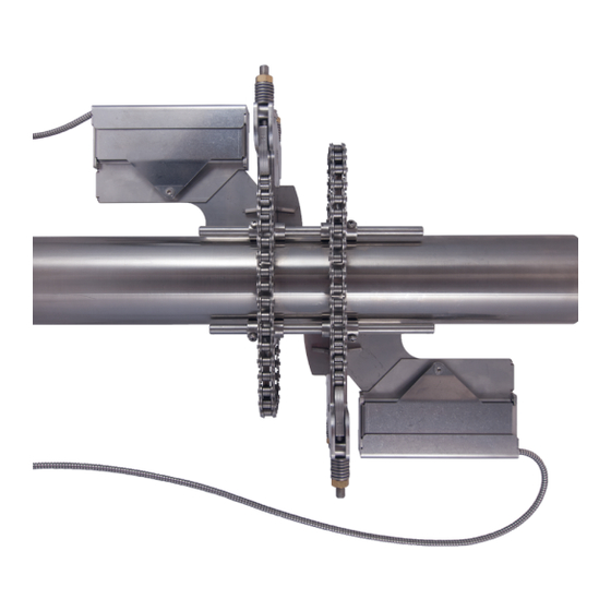
WaveInjector WI-400 Ergänzung zur Betriebsanleitung - DEUTSCH Produktbeschreibung Der WaveInjector ist eine Sensorbefestigung für die Ultraschall-Durchflussmessung bei extremen Temperaturen (siehe Abb. 3.1 und Abb. 3.2). Für den Einsatztemperaturbereich des WaveInjectors siehe Technische Spezifikation. Ausführungen Abb. 3.1: WaveInjector WI-400x-xx-C (hier Durchstrahlungsanordnung) 1 –... -
Seite 9: Montage
Ergänzung zur Betriebsanleitung - DEUTSCH WaveInjector WI-400 Montage Warnung! Montage, Anschluss und Inbetriebnahme von nicht autorisiertem und befähigtem Personal Es kann zu Personen- oder Sachschäden sowie gefährlichen Situationen kommen. → Arbeiten am Messumformer dürfen nur von autorisiertem und befähigtem Personal durchgeführt wer- den. -
Seite 10: Rohre Mit Thermischer Isolation
WaveInjector WI-400 Ergänzung zur Betriebsanleitung - DEUTSCH Wenn das Rohr eine thermische Isolation hat, muss diese angepasst werden. Für die Mindestabstände zwischen Koppel- platte und Isolation siehe Abschnitt 4.1.1. Wenn das Rohr eine Begleitheizung hat, darf es keinen direkten Kontakt zwischen der Koppelplatte und der Begleithei- zung geben. -
Seite 11: Rohre Mit Begleitheizung
Ergänzung zur Betriebsanleitung - DEUTSCH WaveInjector WI-400 4.1.2 Rohre mit Begleitheizung Wichtig! Bei Überhitzung der Sensoren kann es zum Ausfall der Messung oder zur Beschädigung der Sensoren kommen. Beach- ten Sie den Mindestabstand zwischen Koppelplatte und Begleitheizung (siehe Abb. 4.3). Es darf keinen direkten Kontakt zwischen der Koppelplatte und der Begleitheizung geben. -
Seite 12: Witterungsschutz Am Waagerechten Rohr
WaveInjector WI-400 Ergänzung zur Betriebsanleitung - DEUTSCH Witterungsschutz am waagerechten Rohr Für die Mindestabstände zwischen Koppelplatte und Witterungsschutz siehe Tab. 4.1. Tab. 4.1: Mindestabstände zwischen Koppelplatte und Witterungsschutz 1 – Witterungsschutz Fluidtemperatur ≤ 400 °C a ≥ 60 mm b ≥ 100 mm Fluidtemperatur >... -
Seite 13: Witterungsschutz Am Senkrechten Rohr
Ergänzung zur Betriebsanleitung - DEUTSCH WaveInjector WI-400 Witterungsschutz am senkrechten Rohr Für die Mindestabstände zwischen Koppelplatte und Witterungsschutz siehe Tab. 4.2. Tab. 4.2: Mindestabstände zwischen Koppelplatte und Witterungsschutz A - A 1 – Witterungsschutz Fluidtemperatur ≤ 400 °C b ≥ 100 mm Fluidtemperatur >... -
Seite 14: Montage Der Kettenhalter, Bügel Und Rohrhalterungen
WaveInjector WI-400 Ergänzung zur Betriebsanleitung - DEUTSCH Montage der Kettenhalter, Bügel und Rohrhalterungen • Wählen Sie die Messstelle entsprechend den Hinweisen in Abschnitt 4.1 aus. • Für die Montage des Messumformers siehe Betriebsanleitung FLUXUS. • Für den Anschluss der Sensoren und der Spannungsversorgung an den Messumformer siehe Betriebsanleitung FLUXUS. -
Seite 15: Montage Für Waveinjector Wi-400X-Xx-C (Durchstrahlungsanordnung)
Ergänzung zur Betriebsanleitung - DEUTSCH WaveInjector WI-400 Abb. 4.5: Schritte zur Anbringung der Markierungen (Reflexanordnung) WI Clamp dist. (siehe Abschnitt 5.2) Schritt 1 Schritt 2 Schritt 3 Schritt 4 M1, M2 4.2.2 Montage für WaveInjector WI-400x-xx-C (Durchstrahlungsanordnung) Bei der Messung in der Durchstrahlungsanordnung werden Kettenhalter und Bügel auf gegenüberliegenden Seiten des Rohrs montiert (siehe Abb. -
Seite 16: Montageschritte Im Überblick
WaveInjector WI-400 Ergänzung zur Betriebsanleitung - DEUTSCH Montageschritte im Überblick Für eine detaillierte Beschreibung der Montage siehe Abschnitte unten. Schritt 1 Schritt 2 Schritt 3 Schritt 4 Schritt 5 2018-01-19, SUFLUXUS_WIV4-3DE... - Seite 17 Ergänzung zur Betriebsanleitung - DEUTSCH WaveInjector WI-400 Schritt 6 Schritt 7 Schritt 8 Schritt 9 Schritt 10 2018-01-19, SUFLUXUS_WIV4-3DE...
-
Seite 18: Aufbau Von Bügel Und Kettenhalter
WaveInjector WI-400 Ergänzung zur Betriebsanleitung - DEUTSCH Aufbau von Bügel und Kettenhalter Abb. 4.8: Aufbau von Bügel und Kettenhalter 1 – Bügel 2 – Schraube (Bügel) 3 – Koppelplattenausschnitt 4 – Tellerfederpakete 5 – Mutter 6 – Andrückschraube 7 – Kettenhalter 8 –... - Seite 19 Ergänzung zur Betriebsanleitung - DEUTSCH WaveInjector WI-400 Abb. 4.10: Montage mit Adapterstangen 1 – Adapterstangen • Setzen Sie den montierten Bügel und Kettenhalter auf das Rohr (siehe Abb. 4.11). Abb. 4.11: Positionierung auf dem Rohr • Drücken Sie die Kette in den Kettenhaken des Bügels (Haken innen) (siehe Abb. 4.12). •...
- Seite 20 WaveInjector WI-400 Ergänzung zur Betriebsanleitung - DEUTSCH Abb. 4.13: Montierter Bügel A und Kettenhalter A Montage des Bügels B • Messen Sie den Abstand l zwischen Kette und Kettenhalter A (siehe Abb. 4.13 und Abb. 4.14). • Drehen Sie die Installation am Rohr um 180° (siehe Abb. 4.15). Abb.
- Seite 21 Ergänzung zur Betriebsanleitung - DEUTSCH WaveInjector WI-400 Abb. 4.16: Montage des Bügels B 1 – Schraube Abb. 4.17: Bügel B im Abstand l • Setzen Sie Bügel und Führungsstangen auf das Rohr (siehe Abb. 4.18). • Positionieren Sie den Bügel gegenüber dem Kettenhalter. Abb.
- Seite 22 WaveInjector WI-400 Ergänzung zur Betriebsanleitung - DEUTSCH Abb. 4.19: Montage der Kette 1 – Muttern Abb. 4.20: Abstände a1 und a2 Abb. 4.21: Um 180° gedrehte Installation 2018-01-19, SUFLUXUS_WIV4-3DE...
- Seite 23 Ergänzung zur Betriebsanleitung - DEUTSCH WaveInjector WI-400 Entfernen des Bügels A • Entfernen Sie die Kette und den Bügel A vom Rohr (siehe Abb. 4.21 und Abb. 4.22). • Drehen Sie die Installation am Rohr um 180° (siehe Abb. 4.23). Abb.
- Seite 24 WaveInjector WI-400 Ergänzung zur Betriebsanleitung - DEUTSCH Abb. 4.25: Abstand zwischen Bügel und Kettenhalter (Seitenansicht) WI Clamp dist. Abb. 4.26: Um 180° gedrehte Installation Montage des Bügels A • Setzen Sie den Bügel A im Abstand WI Clamp dist. auf das Rohr (siehe Abschnitt 5.2 und Abb. 4.27). •...
-
Seite 25: Ausrichtung Der Installation
Ergänzung zur Betriebsanleitung - DEUTSCH WaveInjector WI-400 Abb. 4.27: Montage des Bügels A 1 – Schraube Abb. 4.28: Montage der Kette 1 – Muttern Ausrichtung der Installation • Positionieren Sie Bügel und Kettenhalter an den Markierungen an den Seiten des Rohrs (siehe Abb. 4.4). Verwenden Sie für die Ausrichtung den Rohrhobel. -
Seite 26: Montage Für Waveinjector Wi-400X-Xx-C (Reflexanordnung)
WaveInjector WI-400 Ergänzung zur Betriebsanleitung - DEUTSCH Abb. 4.29: Ausrichtung der Installation 1 – Tellerfederpakete 2 – Muttern 4.2.3 Montage für WaveInjector WI-400x-xx-C (Reflexanordnung) Bei der Messung in Reflexanordnung werden die Bügel auf derselben Seite des Rohrs montiert (siehe Abb. 4.30). Abb. - Seite 27 Ergänzung zur Betriebsanleitung - DEUTSCH WaveInjector WI-400 Montage der Bügel Hinweis! Für die Montage am waagerechten Rohr: Wählen Sie eine Messstelle, wo die Sensoren seitlich am Rohr befestigt werden können, so dass sich die Schallwellen horizontal im Rohr ausbreiten. Damit können Feststoffe oder Flüssig- keit am Rohrboden oder Gasblasen an der Rohroberseite die Ausbreitung des Signals nicht beeinflussen.
- Seite 28 WaveInjector WI-400 Ergänzung zur Betriebsanleitung - DEUTSCH Abb. 4.35: Montage der Kette Ausrichtung der Installation • Positionieren Sie die Bügel an den Markierungen an den Seiten des Rohrs (siehe Abb. 4.5). Verwenden Sie für die Aus- richtung den Rohrhobel. • Ziehen Sie die Muttern der beiden Bügel fest (siehe Abb. 4.36): –...
-
Seite 29: Montage Für Waveinjector Wi-400X-Xx-T
Ergänzung zur Betriebsanleitung - DEUTSCH WaveInjector WI-400 4.2.4 Montage für WaveInjector WI-400x-xx-T Bei der Messung in der Durchstrahlungsanordnung zeigen die Andrückschrauben der Rohrhalterungen in entgegen- gesetzte Richtungen (siehe Abb. 4.37). Bei der Messung in der Reflexanordnung zeigen die Andrückschrauben der Rohrhalterungen in die gleiche Richtung (siehe Abb. -
Seite 30: Aufbau Der Rohrhalterung
WaveInjector WI-400 Ergänzung zur Betriebsanleitung - DEUTSCH Aufbau der Rohrhalterung Die Rohrhalterung hat 2 Bügel, die durch 2 Gewindestangen verbunden sind (siehe Abb. 4.39). Ein Bügel ist auf den Ge- windestangen verschiebbar. Der andere Bügel ist mit Muttern fixiert. Er hat eine Andrückschraube zur Befestigung der Koppelplatte und 3 Tellerfederpakete zum Ausgleich von Rohrdurchmesseränderungen bei Temperaturschwankungen. -
Seite 31: Ausrichtung Der Rohrhalterungen
Ergänzung zur Betriebsanleitung - DEUTSCH WaveInjector WI-400 Abb. 4.40: Montierte Rohrhalterungen (Durchstrahlungsanordnung, Draufsicht) WI Clamp dist. 1 – Andrückschraube Abb. 4.41: Montierte Rohrhalterungen (Durchstrahlungsanordnung, Seitenansicht) Ausrichtung der Rohrhalterungen • Richten Sie die Koppelplattenausschnitte beider Rohrhalterungen mit Hilfe des Rohrhobels aus. Der Rohrhobel muss durch die Koppelplattenausschnitte der Rohrhalterungen auf beiden Seiten des Rohrs leicht geführt werden können (siehe Abb. -
Seite 32: Montage Der Koppelplatten
WaveInjector WI-400 Ergänzung zur Betriebsanleitung - DEUTSCH Abb. 4.43: Ausrichtung der Rohrhalterungen (Seitenansicht) Montage der Koppelplatten Im Folgenden wird die Montage der Koppelplatten in der Durchstrahlungsanordnung beschrieben. Die Koppelplatten wer- den auf gegenüberliegenden Seiten des Rohrs montiert. Die Montage der Koppelplatten in der Reflexanordnung erfolgt analog. Die Koppelplatten werden auf derselben Seite des Rohrs montiert. - Seite 33 Ergänzung zur Betriebsanleitung - DEUTSCH WaveInjector WI-400 Abb. 4.45: Glättung der Messstelle (Seitenansicht) 1 – Rohrhobel • Schieben Sie den Rohrhobel gleichmäßig hin und her: – Die Unterseite des Rohrhobels muss parallel zur Rohroberfläche ausgerichtet sein. – Der abgehobene Span muss sehr dünn und gleichmäßig sein. Es dürfen keine Rattermarken entstehen. Falls erfor- derlich, stellen Sie die Schneide des Rohrhobels so ein, dass sie nur wenig (<...
-
Seite 34: Demontage Der Sensorbox
WaveInjector WI-400 Ergänzung zur Betriebsanleitung - DEUTSCH Abb. 4.47: Länge der Rohrkoppelfläche 1 – Rohrkoppelfläche der Koppelplatte Demontage der Sensorbox • Lösen Sie die 2 Schrauben an der Sensorbox (siehe Abb. 4.48). Die Skalenschraube darf nicht gelöst werden. • Entfernen Sie die Abdeckung. •... - Seite 35 Ergänzung zur Betriebsanleitung - DEUTSCH WaveInjector WI-400 Montage der Koppelplatten am Rohr • Schieben Sie die Koppelplatte durch den Koppelplattenausschnitt der Rohrhalterung, bis sich die Mitte der Spannfläche unter der Andrückschraube der Rohrhalterung befindet (siehe Abb. 4.50 und Abb. 4.52). •...
- Seite 36 WaveInjector WI-400 Ergänzung zur Betriebsanleitung - DEUTSCH Abb. 4.52: Spannfläche der Koppelplatte 1 – Mitte der Spannfläche • Prüfen Sie den Koppelplattenabstand WI Plate dist. (siehe Abb. 4.53). Der Abstand muss mit dem Wert überein- stimmen, der am Messumformer angezeigt wird (siehe Abschnitt 5.2). •...
- Seite 37 Ergänzung zur Betriebsanleitung - DEUTSCH WaveInjector WI-400 Abb. 4.54: Negativer Koppelplattenabstand (nur in der Durchstrahlungsanordnung, Draufsicht) WI Plate dist. Abb. 4.55: Koppelplatte in Rohrhalterung des gegenüberliegenden Sensors (nur in der Durchstrahlungsanordnung, Draufsicht) Rohrhalterung des gegenüberliegenden Sensors Koppelplatte 2018-01-19, SUFLUXUS_WIV4-3DE...
-
Seite 38: Montage Der Sensoren
WaveInjector WI-400 Ergänzung zur Betriebsanleitung - DEUTSCH Montage der Sensoren Montage der Sensoren in den Abdeckungen • Drücken Sie die Sensoren auf die Sensorhalterungen in den Abdeckungen, so dass die Sensoren einrasten und fest fi- xiert sind (siehe Abb. 4.56). •... -
Seite 39: Positionierung Der Sensoren In Den Abdeckungen
Ergänzung zur Betriebsanleitung - DEUTSCH WaveInjector WI-400 Positionierung der Sensoren in den Abdeckungen Für die Positionierung der Sensoren in den Abdeckungen muss der Skalenwert k bestimmt werden (siehe Abb. 4.60). Der Skalenwert wird bestimmt mit folgender Gleichung: a l – --------- - Sensorabstand Transd. - Seite 40 WaveInjector WI-400 Ergänzung zur Betriebsanleitung - DEUTSCH Abb. 4.61: Positionierung der Sensoren in den Abdeckungen (Draufsicht) Inch 20 30 40 50 60 1 – Skalenschraube Montage der Sensoren am Rohr • Bringen Sie Koppelfolie auf die Kontaktfläche eines Sensors (siehe Abb. 4.62). Die Koppelfolie kann mit ein wenig Kop- pelpaste auf der Sensorkontaktfläche fixiert werden.
- Seite 41 Ergänzung zur Betriebsanleitung - DEUTSCH WaveInjector WI-400 Abb. 4.62: Montage der Sensoren (Durchstrahlungsanordnung, Draufsicht) 1 – Kunststoff-Koppelfolie 2 – Schrauben Die Gravuren auf den Abdeckungen ergeben einen Pfeil. Die Sensorkabel zeigen in entgegengesetzte Richtungen (siehe Abb. 4.63). Abb. 4.63: Montage der Sensoren (Reflexanordnung, Seitenansicht) 1 –...
- Seite 42 WaveInjector WI-400 Ergänzung zur Betriebsanleitung - DEUTSCH Kontrolle des Sensorabstands • Prüfen Sie den Sensorabstand nach ca. 30 Minuten am Messumformer (siehe Abschnitt 5.2), wenn die metallische Kop- pelfolie Betriebstemperatur hat. • Messen Sie den Sensorabstand a (siehe Abb. 4.61): a = 2 ·...
-
Seite 43: Optimierung Des Sensorabstands
Ergänzung zur Betriebsanleitung - DEUTSCH WaveInjector WI-400 Optimierung des Sensorabstands Am Messumformer werden immer noch die Installationsparameter angezeigt (siehe Abschnitt 5.2). • Drücken Sie ENTER. • Geben Sie den Sensorabstand ein. • Für die Optimierung des Sensorabstands siehe Betriebsanleitung FLUXUS. •... -
Seite 44: Inbetriebnahme
WaveInjector WI-400 Ergänzung zur Betriebsanleitung - DEUTSCH Inbetriebnahme Einstellungen am Messumformer Aktivierung des WaveInjector-Modus SYSTEM-Einstel.\Messung • Wählen Sie Sonderfunktion\SYSTEM-Einstel.\Messung. Für die Auswahl der Menüpunkte siehe Betriebsanleitung FLUXUS. SYSTEM-Einstel.\Messung\WaveInjector • Drücken Sie ENTER, bis WaveInjector angezeigt wird. • Wählen Sie ein, um den WaveInjector-Modus zu aktivieren. •... -
Seite 45: Ausgabe Der Installationsparameter
Ergänzung zur Betriebsanleitung - DEUTSCH WaveInjector WI-400 Tab. 5.1: Koppelplatten des WaveInjectors Koppelplatte WI-400 WI-400KG Sensortyp M, P, Q K, G Abmessungen 242.5 mm 279 mm Nach der Parametereingabe wird das Hauptmenü angezeigt. Ausgabe der Installationsparameter Starten Sie eine Messung, um die Installationsparameter des WaveInjectors anzuzeigen. •... - Seite 46 WaveInjector WI-400 Ergänzung zur Betriebsanleitung - DEUTSCH Abb. 5.1: Installationsparameter des WaveInjectors (Draufsicht) Transd. dist. WI Clamp dist. WI Plate dist. 2018-01-19, SUFLUXUS_WIV4-3DE...
-
Seite 47: Automatisches Wi-Werkzeug (Option)
Ergänzung zur Betriebsanleitung - DEUTSCH WaveInjector WI-400 Automatisches WI-Werkzeug (Option) Gefahr! Gefahr einer Explosion beim Einsatz des automatischen WI-Werkzeugs in explosionsgefährdeten Bereichen Es kann zu Personen- oder Sachschäden sowie gefährlichen Situationen kommen. → Das automatische WI-Werkzeug ist nicht für den Einsatz in explosionsgefährdeten Bereichen bestimmt. -
Seite 48: Vorbereitung Der Messstelle
WaveInjector WI-400 Ergänzung zur Betriebsanleitung - DEUTSCH Vorbereitung der Messstelle Wichtig! Bei heißen Rohren kann das automatische WI-Werkzeug durch zu lange Hitzeeinwirkung beschädigt werden. Die Schritte zum Glätten des Rohrs müssen zügig erfolgen. Eine zu lange Hitzeeinwirkung macht sich oft dadurch bemerkbar, dass das automatische WI-Werkzeug beim Vorhub ein klopfendes Geräusch macht. - Seite 49 Schneidfläche nach unten in das automatische WI-Werkzeug eingebaut und weiter verwendet werden. Wenn beide Schneidflächen verschlissen sind, muss der Schneidkörper ersetzt werden. Nehmen Sie Kontakt mit FLEXIM auf. • Setzen Sie den Schneidkörper in das automatische WI-Werkzeug ein. Er kann von beiden Seiten eingesetzt werden.
- Seite 50 WaveInjector WI-400 Ergänzung zur Betriebsanleitung - DEUTSCH 2018-01-19, SUFLUXUS_WIV4-3DE...
-
Seite 51: Supplement To Operating Instruction - English
Supplement to operating instruction - ENGLISH WaveInjector WI-400 SUFLUXUS_WIV4-3EN FLUXUS F60x FLUXUS F70x FLUXUS F80x FLUXUS ADM 8027... - Seite 52 FLUXUS is a registered trademark of FLEXIM GmbH. FLEXIM GmbH Boxberger Str. 4 12681 Berlin Germany Tel.: +49 (30) 936 67 660 Fax: +49 (30) 936 67 680 E-mail: info@flexim.com www.flexim.com Supplement to operating instruction FLUXUS SUFLUXUS_WIV4-3EN, 2018-01-19 Copyright (©) FLEXIM GmbH 2018...
- Seite 53 Supplement to operating instruction - ENGLISH WaveInjector WI-400 Table of contents Introduction ................54 Safety instructions .
-
Seite 54: Introduction
Copyright The content of this supplement is subject to changes without prior notice. All rights reserved. No part of this supplement may be reproduced in any form without FLEXIM's written permission. 2018-01-19, SUFLUXUS_WIV4-3EN... -
Seite 55: Safety Instructions
The measuring equipment comprises the transmitter, the transducers and the accessories. If troubles or damages have occurred during installation or operation of the measuring equipment, please inform FLEXIM. If the measuring point is within an explosive atmosphere, the danger zone and present explosive atmosphere have to be determined. -
Seite 56: Product Description
WaveInjector WI-400 Supplement to operating instruction - ENGLISH Product description The WaveInjector is a transducer mounting fixture for the ultrasonic flow measurement at extreme temperatures, see Fig. 3.1 and Fig. 3.2. For the operating temperature range of the WaveInjector, see Technical specification. Designs Fig. -
Seite 57: Installation
Supplement to operating instruction - ENGLISH WaveInjector WI-400 Installation Warning! Installation, connection and start-up by unauthorized and unqualified personnel This may result in personal or material damage or other dangerous situations. → Any work on the transmitter has to be carried out by authorized and qualified personnel. Caution! Touching hot or cold surfaces This may result in injuries (e.g., thermal damages). - Seite 58 WaveInjector WI-400 Supplement to operating instruction - ENGLISH If the pipe has a thermal insulation, it has to be adapted. For the minimum distances between coupling plate and insula- tion, see section 4.1.1. If the pipe has a heat tracing, it must not have any contact to the coupling plate. For the minimum distances between cou- pling plate and heat tracing, see section 4.1.2.
- Seite 59 Supplement to operating instruction - ENGLISH WaveInjector WI-400 4.1.2 Pipes with heat tracing Important! An overheating of the transducers can result in measurement failures or transducer damages. Observe the minimum distance between coupling plate and heat tracing, see Fig. 4.3. The heat tracing must not have any contact to the coupling plate.
- Seite 60 WaveInjector WI-400 Supplement to operating instruction - ENGLISH Weather protection on a horizontal pipe For the minimum distances between coupling plate and weather protection, see Tab. 4.1. Tab. 4.1: Minimum distances between coupling plate and weather protection 1 – weather protection fluid temperature ≤...
- Seite 61 Supplement to operating instruction - ENGLISH WaveInjector WI-400 Weather protection an a vertical pipe For the minimum distances between coupling plate and weather protection, see Tab. 4.2. Tab. 4.2: Minimum distances between coupling plate and weather protection A - A 1 –...
-
Seite 62: Installation Of Chain Support, Jaw And Pipe Mounting Fixture
WaveInjector WI-400 Supplement to operating instruction - ENGLISH Installation of chain support, jaw and pipe mounting fixture • Select the measuring point according to the recommendations in section 4.1. • For the installation of the transmitter see operating instruction FLUXUS. •... - Seite 63 Supplement to operating instruction - ENGLISH WaveInjector WI-400 Fig. 4.5: Steps for the marking (reflection arrangement) WI Clamp dist. (see section 5.2) step 1 step 2 step 3 step 4 M1, M2 4.2.2 Installation for the WaveInjector WI-400x-xx-C (diagonal arrangement) When measuring in diagonal arrangement, the chain support and the jaws are installed on the opposite sides of the pipe, see Fig.
- Seite 64 WaveInjector WI-400 Supplement to operating instruction - ENGLISH Overview of the installation steps For a detailed description of the installation see the following sections. step 1 step 2 step 3 step 4 step 5 2018-01-19, SUFLUXUS_WIV4-3EN...
- Seite 65 Supplement to operating instruction - ENGLISH WaveInjector WI-400 step 6 step 7 step 8 step 9 step 10 2018-01-19, SUFLUXUS_WIV4-3EN...
- Seite 66 WaveInjector WI-400 Supplement to operating instruction - ENGLISH Components of jaw and chain support Fig. 4.8: Components of jaw and chain support 1 – jaw 2 – screw (jaw) 3 – coupling plate aperture 4 – disk spring package 5 – nut 6 –...
- Seite 67 Supplement to operating instruction - ENGLISH WaveInjector WI-400 Fig. 4.10: Installation of the fitting pieces 1 – fitting pieces • Place the installed jaw and chain support on the pipe, see Fig. 4.11. Fig. 4.11: Positioning on the pipe • Push the chain into the hooks of the jaw (inner cog), see Fig. 4.12. •...
- Seite 68 WaveInjector WI-400 Supplement to operating instruction - ENGLISH Fig. 4.13: Installed jaw (A) and chain support (A) Installation of the jaw (B) • Measure the distance l between chain and chain support (A), see Fig. 4.13 and Fig. 4.14. • Rotate the installation through 180°, see Fig. 4.15. Fig.
- Seite 69 Supplement to operating instruction - ENGLISH WaveInjector WI-400 Fig. 4.16: Installation of the jaw (B) 1 – screw Fig. 4.17: Jaw (B) in the distance I • Place the jaw and the guiding rods on the pipe, see Fig. 4.18. •...
- Seite 70 WaveInjector WI-400 Supplement to operating instruction - ENGLISH Fig. 4.19: Installation of the chain 1 – nuts Fig. 4.20: Distances a1 and a2 Fig. 4.21: Installation rotated through 180° 2018-01-19, SUFLUXUS_WIV4-3EN...
- Seite 71 Supplement to operating instruction - ENGLISH WaveInjector WI-400 Removal of the jaw (A) • Remove the chain and the jaw (A) from the pipe, see Fig. 4.21 and Fig. 4.22. • Rotate the installation through 180°, see Fig. 4.23. Fig. 4.22: Removal of the jaw (A) Fig.
- Seite 72 WaveInjector WI-400 Supplement to operating instruction - ENGLISH Fig. 4.25: Distance between jaw and chain support (side view) WI Clamp dist. Fig. 4.26: Installation rotated through 180° Installation of the jaw (A) • Place the jaw (A) in the distance WI Clamp dist. on the pipe, see section 5.2 and Fig. 4.27. •...
- Seite 73 Supplement to operating instruction - ENGLISH WaveInjector WI-400 Fig. 4.27: Installation of the jaw (A) 1 – screw Fig. 4.28: Installation of the chain 1 – nuts Alignment of the installation • Place the jaw and the chain support on the markings made on the pipe, see Fig. 4.4. Use the pipe planer for the align- ment.
- Seite 74 WaveInjector WI-400 Supplement to operating instruction - ENGLISH Fig. 4.29: Alignment of the installation 1 – disk spring package 2 – nuts 4.2.3 Installation for the WaveInjector WI-400x-xx-C (reflection arrangement) When measuring in reflection arrangement, the jaws are mounted on the same side of the pipe, see Fig. 4.30. Fig.
- Seite 75 Supplement to operating instruction - ENGLISH WaveInjector WI-400 Installation of the jaws Notice! For the installation on a horizontal pipe, select a measuring point where the transducers can be mounted on the side of the pipe, allowing the sound waves to propagate in the pipe horizontally. Thus, solid or liquid deposits on the bottom of the pipe or gas bubbles in the upper part are prevented from influencing the propagation of the signal.
- Seite 76 WaveInjector WI-400 Supplement to operating instruction - ENGLISH Fig. 4.35: Installation of the chain Alignment of the installation • Place the jaw and the chain support on the markings made on the pipe, see Fig. 4.5. Use the pipe planer for the alignment. •...
- Seite 77 Supplement to operating instruction - ENGLISH WaveInjector WI-400 4.2.4 Installation for the WaveInjector WI-400x-xx-T When measuring in diagonal arrangement, the tensioning screws of the pipe mounting fixtures point in opposite directions, see Fig. 4.37. When measuring in reflection arrangement, the tensioning screws of the pipe mounting fixtures point in the same direction, see Fig.
- Seite 78 WaveInjector WI-400 Supplement to operating instruction - ENGLISH Components of the pipe mounting fixture The pipe mounting fixture consists of 2 jaws connected by 2 threaded rods, see Fig. 4.39. One jaw can be moved along the threaded rods. The other jaw is fixed to the threaded rods with nuts. It has a tensioning screw for fixing the coupling plate and 3 disk spring packages for compensating changes of the pipe diameter in the event of temperature fluctuations.
- Seite 79 Supplement to operating instruction - ENGLISH WaveInjector WI-400 Fig. 4.40: Installed pipe mounting fixture (diagonal arrangement, top view) WI Clamp dist. 1 – tensioning screw Fig. 4.41: Installed pipe mounting fixtures (diagonal arrangement, side view) Alignment of the pipe mounting fixtures •...
-
Seite 80: Installation Of The Coupling Plates
WaveInjector WI-400 Supplement to operating instruction - ENGLISH Fig. 4.43: Alignment of the pipe mounting fixtures (side view) Installation of the coupling plates In the following, the installation of the coupling plates in diagonal arrangement is described. The coupling plates are mounted on opposite sides of the pipe. - Seite 81 Supplement to operating instruction - ENGLISH WaveInjector WI-400 Fig. 4.45: Evening the measuring point (side view) 1 – pipe planer • Move the pipe planer uniformly back and forth. – The bottom side of the pipe planer has to be parallel to the pipe surface. –...
- Seite 82 WaveInjector WI-400 Supplement to operating instruction - ENGLISH Fig. 4.47: Length of the pipe contact surface 1 – pipe contact surface of the coupling plate Disassembly of the transducer box • Loosen the 2 screws of the transducer box, see Fig. 4.48. Do not loosen the positioning screw. •...
- Seite 83 Supplement to operating instruction - ENGLISH WaveInjector WI-400 Installation of the coupling plates on the pipe • Slide the coupling plate through the coupling plate aperture of the pipe mounting fixture until the middle of the clamping surface is below the tensioning screw of the pipe mounting fixture, see Fig. 4.50 and Fig. 4.52. •...
- Seite 84 WaveInjector WI-400 Supplement to operating instruction - ENGLISH Fig. 4.52: Clamping surface of the coupling plate 1 – center of clamping surface • Check the distance between the coupling plates WI Plate dist., see Fig. 4.53. The distance has to correspond to the value displayed by the transmitter, see section 5.2.
- Seite 85 Supplement to operating instruction - ENGLISH WaveInjector WI-400 Fig. 4.54: Negative distance between the coupling plates (only in diagonal arrangement, top view) WI Plate dist. Fig. 4.55: Coupling plate in the pipe mounting fixture of the opposite transducer (only in diagonal arrangement, top view) pipe mounting fixture of the opposite transducer coupling plate...
-
Seite 86: Installation Of The Transducers
WaveInjector WI-400 Supplement to operating instruction - ENGLISH Installation of the transducers Installation of the transducers in the covers • Press the transducers firmly into the transducer mounting fixture in the covers until the transducers are tightly fixed, see Fig. 4.56. •... - Seite 87 Supplement to operating instruction - ENGLISH WaveInjector WI-400 Positioning of the transducer in the covers For the positioning of the transducers in the cover, it is necessary to determine the scale value k, see Fig. 4.60. The scale value is determined using the following equation: a l –...
- Seite 88 WaveInjector WI-400 Supplement to operating instruction - ENGLISH Fig. 4.61: Positioning of the transducers in the covers (top view) Inch 20 30 40 50 60 1 – positioning screw Installation of the transducers on the pipe • Put some coupling foil to the contact surface of the transducer, see Fig. 4.62. The coupling foil can be fixed to the contact surface with a small amount of coupling compound.
- Seite 89 Supplement to operating instruction - ENGLISH WaveInjector WI-400 Fig. 4.62: Installation of the transducers (diagonal arrangement, top view) 1 – plastic coupling foil 2 – screws The engravings on the covers form an arrow. The transducer cables show in opposite directions, see Fig. 4.63. Fig.
- Seite 90 WaveInjector WI-400 Supplement to operating instruction - ENGLISH Transducer distance check • Check the transducer distance in the transmitter after approx. 30 minutes, see section 5.2, when the metallic coupling foil has reached its operating temperature. • Measure the transducer distance a, see Fig. 4.61: a = 2 ·...
-
Seite 91: Optimization Of The Transducer Distance
Supplement to operating instruction - ENGLISH WaveInjector WI-400 Optimization of the transducer distance The transmitter is still displaying the installation parameters, see section 5.2. • Press ENTER. • Enter the transducer distance. • For the optimization of the transducer distance, see operating instruction FLUXUS. •... -
Seite 92: Start-Up
WaveInjector WI-400 Supplement to operating instruction - ENGLISH Start-up Transmitter settings Activation of the WaveInjector mode SYSTEM settings\Measuring • Select Special Funct.\SYSTEM settings\Measuring. For the selection of the menu items see operating instruction FLUXUS. SYSTEM settings\Measuring\WaveInjector • Press ENTER until WaveInjector is displayed. •... -
Seite 93: Output Of The Installation Parameters
Supplement to operating instruction - ENGLISH WaveInjector WI-400 Tab. 5.1: Coupling plates of the WaveInjector coupling plate WI-400 WI-400KG transducer type M, P, Q K, G dimensions 242.5 mm 279 mm After the parameter input, the main menu is displayed. Output of the installation parameters Start a measurement to display the installation parameters of the WaveInjector. - Seite 94 WaveInjector WI-400 Supplement to operating instruction - ENGLISH Fig. 5.1: Installation parameters of the WaveInjector (top view) Transd. dist. WI Clamp dist. WI Plate dist. 2018-01-19, SUFLUXUS_WIV4-3EN...
-
Seite 95: A Automatic Wi Tool (Optional)
Supplement to operating instruction - ENGLISH WaveInjector WI-400 Automatic WI tool (optional) Danger! Risk of explosion when using the automatic WI tool in explosive atmospheres This may result in personal or material damage or other dangerous situations. → The automatic WI tool is not intended for use in explosive atmospheres. Take appropriate precautions according to the applicable rules and standards. - Seite 96 WaveInjector WI-400 Supplement to operating instruction - ENGLISH Preparation of the measuring point Important! On hot pipes, the automatic WI tool can be damaged due to extended heat exposure. The steps for smoothing the pipe have to be carried out in a speedy manner. When the heat exposure becomes to long, the automatic WI tool sometimes begins to make a knocking sound during the forward stroke.
- Seite 97 WI tool with the other cutting edge facing down. If both cutting edges are worn down, the cutting ele- ment has to be replaced. Contact FLEXIM. • Reinsert the cutting element into the automatic WI tool. It can be used from both sides.
- Seite 98 WaveInjector WI-400 Supplement to operating instruction - ENGLISH 2018-01-19, SUFLUXUS_WIV4-3EN...
-
Seite 99: Supplément Au Mode D'emploi - Français
Supplément au mode d’emploi - FRANÇAIS WaveInjector WI-400 SUFLUXUS_WIV4-3FR FLUXUS F60x FLUXUS F70x FLUXUS F80x FLUXUS ADM 8027... - Seite 100 FLUXUS est une marque déposée de FLEXIM GmbH. FLEXIM GmbH Boxberger Str. 4 12681 Berlin Allemagne Tél. : +49 (30) 936 67 660 Fax : +49 (30) 936 67 680 E-mail : info@flexim.com www.flexim.com Supplément au mode d'emploi FLUXUS SUFLUXUS_WIV4-3FR, 2018-01-19 Copyright (©) FLEXIM GmbH 2018...
- Seite 101 Supplément au mode d’emploi - FRANÇAIS WaveInjector WI-400 Table des matières Introduction ................102 Consignes de sécurité...
-
Seite 102: Introduction
Nous tenterons d'en tenir compte pour les prochaines versions. Droit d'auteur Le contenu du présent supplément peut être modifié sans préavis. Tous les droits d'auteur sont réservés à FLEXIM GmbH. Toute reproduction, quelle qu'elle soit, du présent supplément est interdite sans l'accord écrit de FLEXIM. -
Seite 103: Consignes De Sécurité
FLUXUS. Le non-respect des instructions, notamment des consignes de sécurité, représente un risque pour la santé et peut entraîner des dommages matériels. Si vous avez des questions, veuillez contacter FLEXIM. Pendant l'installation et le fonctionnement de l'équipement de mesure, respectez les conditions ambiantes et d'installation indiquées dans la documentation. -
Seite 104: Description Du Produit
WaveInjector WI-400 Supplément au mode d’emploi - FRANÇAIS Description du produit Le WaveInjector est une fixation pour capteur dédiée à la mesure du débit par ultrasons à des températures extrêmes (voir Fig. 3.1 et Fig. 3.2). Pour la plage de températures de service du WaveInjector, voir la Spécification technique. Modèles Fig. -
Seite 105: Montage
Supplément au mode d’emploi - FRANÇAIS WaveInjector WI-400 Montage Avertissement ! Montage, raccordement et mise en service par du personnel non autorisé et non qualifié Des dommages corporels ou matériels ainsi que des situations dangereuses peuvent survenir. → Les travaux sur le transmetteur doivent être effectués par du personnel autorisé et qualifié. Attention ! Contact avec des surfaces très chaudes ou froides Risque de blessures (p. - Seite 106 WaveInjector WI-400 Supplément au mode d’emploi - FRANÇAIS Si la conduite possède une isolation thermique, celle-ci doit être adaptée. Pour les distances minimales entre la lame de couplage et l'isolation, voir section 4.1.1. Si la conduite possède un chauffage par traçage, celui-ci ne doit présenter aucun contact direct avec la lame de couplage. Pour la distance minimale entre la lame de couplage et le chauffage par traçage, voir section 4.1.2.
- Seite 107 Supplément au mode d’emploi - FRANÇAIS WaveInjector WI-400 4.1.2 Conduites avec chauffage par traçage Important ! Une surchauffe des capteurs peut conduire à la défaillance de la mesure ou à l'endommagement des capteurs. Obser- vez la distance minimale entre la lame de couplage et le chauffage par traçage (voir Fig. 4.3). La lame de couplage ne doit présenter aucun contact direct avec le chauffage par traçage.
- Seite 108 WaveInjector WI-400 Supplément au mode d’emploi - FRANÇAIS Protection des intempéries sur une conduite horizontale Pour les distances minimales entre la lame de couplage et la protection des intempéries, voir Tab. 4.1. Tab. 4.1: Distances minimales entre la lame de couplage et la protection des intempéries 1 –...
- Seite 109 Supplément au mode d’emploi - FRANÇAIS WaveInjector WI-400 Protection des intempéries sur une conduite verticale Pour les distances minimales entre la lame de couplage et la protection des intempéries, voir Tab. 4.2. Tab. 4.2: Distances minimales entre la lame de couplage et la protection des intempéries A - A 1 –...
-
Seite 110: Montage Des Supports De Chaînes, Étriers Et Dispositifs De Fixation À La Conduite
WaveInjector WI-400 Supplément au mode d’emploi - FRANÇAIS Montage des supports de chaînes, étriers et dispositifs de fixation à la conduite • Sélectionnez le point de mesure en suivant les recommandations données dans la section 4.1. • Pour le montage du transmetteur, voir le mode d'emploi FLUXUS. •... - Seite 111 Supplément au mode d’emploi - FRANÇAIS WaveInjector WI-400 Fig. 4.5 : Étapes de repérage (montage réflexion) WI Clamp dist. (voir section 5.2) Étape 1 Étape 2 Étape 3 Étape 4 M1, M2 4.2.2 Montage pour le WaveInjector WI-400x-xx-C (montage diagonal) Pour la mesure en montage diagonal, les supports de chaînes et les étriers sont montés sur des côtés opposés de la conduite (voir Fig.
- Seite 112 WaveInjector WI-400 Supplément au mode d’emploi - FRANÇAIS Étapes de montage Pour une description détaillée de la montage, voir les sections ci-dessous. Étape 1 Étape 2 Étape 3 Étape 4 Étape 5 2018-01-19, SUFLUXUS_WIV4-3FR...
- Seite 113 Supplément au mode d’emploi - FRANÇAIS WaveInjector WI-400 Étape 6 Étape 7 Étape 8 Étape 9 Étape 10 2018-01-19, SUFLUXUS_WIV4-3FR...
- Seite 114 WaveInjector WI-400 Supplément au mode d’emploi - FRANÇAIS Ensemble de l'étrier et du support de chaîne Fig. 4.8 : Ensemble de l'étrier et du support de chaîne 1 – étrier 2 – vis (étrier) 3 – découpe pour la lame de couplage 4 –...
- Seite 115 Supplément au mode d’emploi - FRANÇAIS WaveInjector WI-400 Fig. 4.10 : Montage avec raccords 1 – raccords • Placez l'étrier et le support de chaîne montés sur la conduite (voir Fig. 4.11). Fig. 4.11 : Positionnement sur la conduite • Pressez la chaîne dans le crochet de l'étrier (dents à côté intérieur, voir Fig. 4.12). •...
- Seite 116 WaveInjector WI-400 Supplément au mode d’emploi - FRANÇAIS Fig. 4.13 : Étrier A et support de chaîne A montés Montage de l'étrier B • Mesurez l'écart l entre la chaîne et le support de chaîne A (voir Fig. 4.13 et Fig. 4.14). •...
- Seite 117 Supplément au mode d’emploi - FRANÇAIS WaveInjector WI-400 Fig. 4.16 : Montage de l'étrier B 1 – vis Fig. 4.17 : Étrier B à l'écart l • Placez l'étrier et les tiges de guidage sur la conduite (voir Fig. 4.18). •...
- Seite 118 WaveInjector WI-400 Supplément au mode d’emploi - FRANÇAIS Fig. 4.19 : Montage de la chaîne 1 – écrou Fig. 4.20 : Écarts a1 et a2 Fig. 4.21 : Installation tournée de 180° 2018-01-19, SUFLUXUS_WIV4-3FR...
- Seite 119 Supplément au mode d’emploi - FRANÇAIS WaveInjector WI-400 Retrait de l'étrier A • Retirez la chaîne et l'étrier A de la conduite (voir Fig. 4.21 et Fig. 4.22). • Tournez l'installation de 180° autour de la conduite (voir Fig. 4.23). Fig.
- Seite 120 WaveInjector WI-400 Supplément au mode d’emploi - FRANÇAIS Fig. 4.25 : Écart entre l'étrier et le support de chaîne (vue de côté) WI Clamp dist. Fig. 4.26 : Installation tournée de 180° Montage de l'étrier A • Placez l'étrier A sur la conduite en respectant l'écart WI Clamp dist. (voir section 5.2 et Fig. 4.27). •...
- Seite 121 Supplément au mode d’emploi - FRANÇAIS WaveInjector WI-400 Fig. 4.27 : Montage de l'étrier A 1 – vis Fig. 4.28 : Montage de la chaîne 1 – écrou Alignement de l'installation • Positionnez l'étrier et le support de chaîne sur les repères sur les côtés de la conduite (voir Fig. 4.4). Pour l'alignement, utilisez l'outil pour le lissage de la conduite.
- Seite 122 WaveInjector WI-400 Supplément au mode d’emploi - FRANÇAIS Fig. 4.29 : Alignement de l'installation 1 – bloc de ressorts à disques 2 – écrou 4.2.3 Montage pour le WaveInjector WI-400x-xx-C (montage réflexion) Pour la mesure en montage réflexion, les étriers sont montés sur le même côté de la conduite (voir Fig. 4.30). Fig.
- Seite 123 Supplément au mode d’emploi - FRANÇAIS WaveInjector WI-400 Montage des étriers Avis ! Si la conduite est horizontale, sélectionnez un point de mesure où les capteurs peuvent être fixés latéralement sur la conduite, de sorte que les ondes sonores se propagent horizontalement dans celle-ci. Les matières solides ou le liquide au fond de la conduite et les bulles gazeuses dans le haut ne peuvent alors pas influencer la propagation du signal.
- Seite 124 WaveInjector WI-400 Supplément au mode d’emploi - FRANÇAIS Fig. 4.35 : Montage de la chaîne Alignement de l'installation • Positionnez les étriers sur les repères sur le côté de la conduite (voir Fig. 4.5). Pour l'alignement, utilisez l'outil pour le lis- sage de la conduite.
- Seite 125 Supplément au mode d’emploi - FRANÇAIS WaveInjector WI-400 4.2.4 Montage pour le WaveInjector WI-400x-xx-T En montage diagonal, les vis de pression des dispositifs de fixation à la conduite pointent dans des directions opposées (voir Fig. 4.37). En montage réflexion, les vis de pression des dispositifs de fixation à la conduite pointent dans la même direction (voir Fig. 4.38). Fig.
- Seite 126 WaveInjector WI-400 Supplément au mode d’emploi - FRANÇAIS Ensemble du dispositif de fixation à la conduite Le dispositif de fixation à la conduite possède 2 étriers reliés entre eux par 2 tiges filetées (voir Fig. 4.39). L'un des étriers peut coulisser sur les tiges filetées, l'autre est fixé à l'aide des écrous. Ce dernier possède une vis de pression pour fixer la lame de couplage et 3 blocs de ressorts à...
- Seite 127 Supplément au mode d’emploi - FRANÇAIS WaveInjector WI-400 Fig. 4.40 : Dispositifs de fixation montés sur la conduite (montage diagonal, vue de dessus) WI Clamp dist. 1 – vis de pression Fig. 4.41 : Dispositifs de fixation montés sur la conduite (montage diagonal, vue de côté) Alignement des dispositifs de fixation à...
-
Seite 128: Montage Des Lames De Couplage
WaveInjector WI-400 Supplément au mode d’emploi - FRANÇAIS Fig. 4.43 : Alignement des dispositifs de fixation à la conduite (vue de côté) Montage des lames de couplage Le montage des lames de couplage (montage diagonal) est décrit ci-après. Les lames de couplage sont montées sur des côtés opposés de la conduite. - Seite 129 Supplément au mode d’emploi - FRANÇAIS WaveInjector WI-400 Fig. 4.45 : Lissage du point de mesure (vue de côté) 1 – outil pour le lissage de la conduite • Poussez l'outil pour le lissage de la conduite de manière homogène de gauche à droite. –...
- Seite 130 WaveInjector WI-400 Supplément au mode d’emploi - FRANÇAIS Fig. 4.47 : Longueur de la surface de couplage 1 – Surface de couplage de la lame de couplage Démontage de la boîte capteur • Desserrez les 2 vis de la boîte capteur (voir Fig. 4.48). Ne desserrez pas la vis de réglage. •...
- Seite 131 Supplément au mode d’emploi - FRANÇAIS WaveInjector WI-400 Montage des lames de couplage sur la conduite • Faites passer la lame de couplage à travers la découpe correspondante du dispositif de fixation à la conduite jusqu'à ce que le centre de la surface de serrage se trouve sous la vis de pression du dispositif de fixation à la conduite (voir Fig.
- Seite 132 WaveInjector WI-400 Supplément au mode d’emploi - FRANÇAIS Fig. 4.52 : Surface de serrage de la lame de couplage 1 – centre de la surface de serrage • Contrôlez l'écart entre les lames de couplage WI Plate dist. (voir Fig. 4.53). Il doit correspondre à la valeur indiquée par le transmetteur (voir section 5.2).
- Seite 133 Supplément au mode d’emploi - FRANÇAIS WaveInjector WI-400 Fig. 4.54 : Écart entre les lames de couplage négatif (uniquement en montage diagonal, vue de dessus) WI Plate dist. Fig. 4.55 : Lame de couplage dans le dispositif de fixation à la conduite du capteur opposé (uniquement en montage diagonal, vue de dessus) dispositif de fixation à...
-
Seite 134: Montage Des Capteurs
WaveInjector WI-400 Supplément au mode d’emploi - FRANÇAIS Montage des capteurs Fixation des capteurs dans leurs caches • Poussez les capteurs sur les dispositifs de fixation dans les caches, de manière à ce que les capteurs s'enclenchent et qu'ils soient solidement fixés (voir Fig. 4.56). •... - Seite 135 Supplément au mode d’emploi - FRANÇAIS WaveInjector WI-400 Positionnement des capteurs dans leurs caches Pour le positionnement des capteurs dans leurs caches, il faut déterminer la valeur de l'échelle k (voir Fig. 4.60) selon la formule suivante : a l – --------- - avec écart entre les capteurs Transd.
- Seite 136 WaveInjector WI-400 Supplément au mode d’emploi - FRANÇAIS Fig. 4.61 : Positionnement des capteurs dans leurs caches (vue de dessus) Inch 20 30 40 50 60 1 – vis de réglage Montage des capteurs sur la conduite • Appliquez une feuille de couplage sur la surface de contact d'un capteur (voir Fig. 4.62). La feuille de couplage peut être fixée sur la surface de contact du capteur avec un peu de couplant acoustique.
- Seite 137 Supplément au mode d’emploi - FRANÇAIS WaveInjector WI-400 Fig. 4.62 : Montage des capteurs (montage diagonal, vue de dessus) 1 – feuille de couplage synthétique 2 – vis Les repères sur les caches forment une flèche. Les câbles des capteurs partent dans des directions opposées (voir Fig. 4.63). Fig.
- Seite 138 WaveInjector WI-400 Supplément au mode d’emploi - FRANÇAIS Contrôle de l'écart entre les capteurs • Vérifiez l'écart entre les capteurs au bout d'environ 30 minutes sur le transmetteur (voir section 5.2), quand la feuille de couplage métallique sera à la température de service. •...
-
Seite 139: Optimisation De L'écart Entre Les Capteurs
Supplément au mode d’emploi - FRANÇAIS WaveInjector WI-400 Optimisation de l'écart entre les capteurs Le transmetteur indique encore les paramètres d'installation (voir section 5.2). • Appuyez sur ENTER. • Saisissez l'écart entre les capteurs. • Pour l’optimisation de l'écart entre les capteurs, voir le mode d'emploi FLUXUS. •... -
Seite 140: Mise En Service
WaveInjector WI-400 Supplément au mode d’emploi - FRANÇAIS Mise en service Réglages sur le transmetteur Activation du mode WaveInjector Réglage SYSTEME\Mesure • Sélectionnez Autres fonct.\Réglage SYSTEME\Mesure. Pour la sélection des points de menu, voir le mode d'emploi FLUXUS. Réglage SYSTEME\Mesure\WaveInjector •... -
Seite 141: Sortie Des Paramètres D'installation
Supplément au mode d’emploi - FRANÇAIS WaveInjector WI-400 Tab. 5.1 : Lames de couplage du WaveInjector lame de WI-400 WI-400KG couplage type de M, P, Q K, G capteur dimensions 242.5 mm 279 mm Après la saisie des paramètres, le menu principal s'affiche. Sortie des paramètres d'installation Démarrez une mesure pour afficher les paramètres d'installation du WaveInjector. - Seite 142 WaveInjector WI-400 Supplément au mode d’emploi - FRANÇAIS Fig. 5.1 : Paramètres d'installation du WaveInjector (vue de dessus) Transd. dist. WI Clamp dist. WI Plate dist. 2018-01-19, SUFLUXUS_WIV4-3FR...
-
Seite 143: A Outil Wi Automatique (Option)
Supplément au mode d’emploi - FRANÇAIS WaveInjector WI-400 Outil WI automatique (option) Danger ! Risque d'explosion lors de l'utilisation de l'outil WI automatique en atmosphère explosible Des dommages corporels ou matériels ainsi que des situations dangereuses peuvent survenir. → L'outil WI automatique n'est pas approprié à une utilisation en atmosphère explosible. Prenez les mesures prévues par les règles et normes en vigueur. - Seite 144 WaveInjector WI-400 Supplément au mode d’emploi - FRANÇAIS Préparation du point de mesure Important ! Sur les conduites brûlantes, l'outil WI automatique peut être endommagé en cas d'exposition prolongée à la chaleur. Les opérations de lissage de la conduite doivent être réalisées rapidement. Une trop longue exposition à la chaleur se manifeste souvent par l'émission de claquements par l'outil WI automatique lors de son avance.
- Seite 145 WI automatique avec l'autre surface de coupe vers le bas et être réutilisé. Si les deux surfaces de coupe sont usées, l'élément coupant doit être remplacé. Veuillez contacter FLEXIM. • Placez l'élément coupant dans l'outil WI automatique. Il peut être inséré des deux côtés.
- Seite 146 WaveInjector WI-400 Supplément au mode d’emploi - FRANÇAIS 2018-01-19, SUFLUXUS_WIV4-3FR...
-
Seite 147: Suplemento De La Instrucción De Empleo - Español
Suplemento de la instrucción de empleo - ESPAÑOL WaveInjector WI-400 SUFLUXUS_WIV4-3ES FLUXUS F60x FLUXUS F70x FLUXUS F80x FLUXUS ADM 8027... - Seite 148 FLUXUS es una marca registrada de la FLEXIM GmbH. FLEXIM GmbH Boxberger Str. 4 12681 Berlin Alemania Tel.: +49 (30) 936 67 660 Fax: +49 (30) 936 67 680 Correo electrónico: info@flexim.com www.flexim.com Suplemento de la instrucción de empleo FLUXUS SUFLUXUS_WIV4-3ES, 2018-01-19 Copyright (©) FLEXIM GmbH 2018...
- Seite 149 Suplemento de la instrucción de empleo - ESPAÑOL WaveInjector WI-400 Índice Introducción ................150 Advertencias de seguridad .
-
Seite 150: Introducción
Derechos de autor El contenido de este suplemento puede ser modificado en cualquier momento. Todos los derechos de autor pertenecen a la empresa FLEXIM GmbH. Sin la autorización escrita por FLEXIM queda prohibida cualquier tipo de reproducción de este suplemento. -
Seite 151: Advertencias De Seguridad
Observe las condiciones ambientales y de instalación, indicadas en la documentación, durante la instalación y el funciona- miento del instrumento de medición. El instrumento de medición consiste en el transmisor, los transductores y el accesorio. Contacte FLEXIM, en caso de que se presenten fallas o daños durante la instalación o el funcionamiento del instrumento de medición. -
Seite 152: Descripción Del Producto
WaveInjector WI-400 Suplemento de la instrucción de empleo - ESPAÑOL Descripción del producto El WaveInjector es un porta-transductores previsto para la medición del caudal por ultrasonido a temperaturas extremas, véase la Fig. 3.1 y la Fig. 3.2. Para el rango de temperatura de funcionamiento del WaveInjector, véase la Especificación técnica. -
Seite 153: Montaje
Suplemento de la instrucción de empleo - ESPAÑOL WaveInjector WI-400 Montaje ¡Advertencia! Montaje, conexión y puesta en marcha por personal no autorizado y calificado Existe la probabilidad de que se produzcan lesiones a personas o daños materiales así como situaciones peligrosas. - Seite 154 WaveInjector WI-400 Suplemento de la instrucción de empleo - ESPAÑOL Si el tubo tiene un aislamiento térmico, este debe ser ajustado. Para las distancias mínimas entre la placa de acoplamien- to y el aislamiento, véase el párrafo 4.1.1. Si el tubo posee un traceado eléctrico, este no debe tener contacto directo con la placa de acoplamiento. Para la distancia mínima entre la placa de acoplamiento y el traceado eléctrico, véase el párrafo 4.1.2.
- Seite 155 Suplemento de la instrucción de empleo - ESPAÑOL WaveInjector WI-400 4.1.2 Tubos con traceado eléctrico ¡Importante! Un sobrecalentamiento de los transductores puede tener como consecuencia fallas de medición o daños de los trans- ductores. Observe la distancia mínima entre la placa de acoplamiento y el traceado eléctrico, véase la Fig. 4.3. El traceado eléctrico y la placa de acoplamiento no deben tener ningún contacto directo.
- Seite 156 WaveInjector WI-400 Suplemento de la instrucción de empleo - ESPAÑOL Protección de la intemperie en un tubo horizontal Para las distancias mínimas entre la placa de acoplamiento y la protección de la intemperie véase la Tab. 4.1. Tab. 4.1: Distancias mínimas entre la placa de acoplamiento y la protección de la intemperie 1 –...
- Seite 157 Suplemento de la instrucción de empleo - ESPAÑOL WaveInjector WI-400 Protección de la intemperie en un tubo vertical Para las distancias mínimas entre la placa de acoplamiento y la protección de la intemperie véase la Tab. 4.2. Tab. 4.2: Distancias mínimas entre la placa de acoplamiento y la protección de la intemperie A - A 1 –...
-
Seite 158: Montaje De Los Soportes De La Cadena, Estribos Y Soportes De Fijación Al Tubo
WaveInjector WI-400 Suplemento de la instrucción de empleo - ESPAÑOL Montaje de los soportes de la cadena, estribos y soportes de fijación al tubo • Seleccione el punto de medición según las recomendaciones del párrafo 4.1. • Para el montaje del transmisor, véase la instrucción de empleo FLUXUS. •... - Seite 159 Suplemento de la instrucción de empleo - ESPAÑOL WaveInjector WI-400 Fig. 4.5: Pasos para colocar las marcas (configuración en modo de reflexión) WI Clamp dist. (véase el párrafo 5.2) paso 1 paso 2 paso 3 paso 4 M1, M2 4.2.2 Montaje para el WaveInjector WI-400x-xx-C (configuración en modo diagonal) En caso de mediciones en configuración en modo diagonal, los soportes de la cadena y los estribos son montados en lados opuestos del tubo, véase la Fig.
- Seite 160 WaveInjector WI-400 Suplemento de la instrucción de empleo - ESPAÑOL Pasos del montaje Para una descripción detallada del montaje, véase los siguientes párrafos. paso 1 paso 2 paso 3 paso 4 paso 5 2018-01-19, SUFLUXUS_WIV4-3ES...
- Seite 161 Suplemento de la instrucción de empleo - ESPAÑOL WaveInjector WI-400 paso 6 paso 7 paso 8 paso 9 paso 10 2018-01-19, SUFLUXUS_WIV4-3ES...
- Seite 162 WaveInjector WI-400 Suplemento de la instrucción de empleo - ESPAÑOL Componentes del estribo y del soporte de la cadena Fig. 4.8: Componentes del estribo y del soporte de la cadena 1 – estribo 2 – tornillo (estribo) 3 – recorte para placa de acoplamiento 4 –...
- Seite 163 Suplemento de la instrucción de empleo - ESPAÑOL WaveInjector WI-400 Fig. 4.10: Montaje de las conexiones 1 – conexiones • Ponga el estribo y soporte de la cadena montado en el tubo, véase la Fig. 4.11. Fig. 4.11: Posicionamiento en el tubo •...
- Seite 164 WaveInjector WI-400 Suplemento de la instrucción de empleo - ESPAÑOL Fig. 4.13: Estribo A y soporte de cadena A montado Montaje del estribo B • Mida la distancia I entre la cadena y el soporte de la cadena A, véase la Fig. 4.13 y la Fig. 4.14. •...
- Seite 165 Suplemento de la instrucción de empleo - ESPAÑOL WaveInjector WI-400 Fig. 4.16: Montaje del estribo B 1 – tornillo Fig. 4.17: Estribo B a la distancia I • Ponga el estribo y vástagos de guía en el tubo, véase la Fig. 4.18. •...
- Seite 166 WaveInjector WI-400 Suplemento de la instrucción de empleo - ESPAÑOL Fig. 4.19: Montaje de la cadena 1 – tuercas Fig. 4.20: Distancias a1 y a2 Fig. 4.21: Instalación girada por 180° 2018-01-19, SUFLUXUS_WIV4-3ES...
- Seite 167 Suplemento de la instrucción de empleo - ESPAÑOL WaveInjector WI-400 Retiro del estribo A • Remueva la cadena y el estribo A del tubo, véase la Fig. 4.21 y la Fig. 4.22. • Gire la instalación por 180°, véase la Fig. 4.23. Fig.
- Seite 168 WaveInjector WI-400 Suplemento de la instrucción de empleo - ESPAÑOL Fig. 4.25: Distancia entre el estribo y el soporte de la cadena (vista lateral) WI Clamp dist. Fig. 4.26: Instalación girada por 180° Montaje del estribo A • Ponga el estribo A a la distancia WI Clamp dist. en el tubo, véase el párrafo 5.2 y la Fig. 4.27. •...
- Seite 169 Suplemento de la instrucción de empleo - ESPAÑOL WaveInjector WI-400 Fig. 4.27: Montaje del estribo A 1 – tornillo Fig. 4.28: Montaje de la cadena 1 – tuercas Posicionamiento de la instalación • Posicione los estribos y los soportes de la cadena en las marcas puestas en el tubo, véase la Fig. 4.4. Para el posiciona- miento, utilice el cepillo de tubo.
- Seite 170 WaveInjector WI-400 Suplemento de la instrucción de empleo - ESPAÑOL Fig. 4.29: Orientación de la instalación 1 – paquete de resortes de disco 2 – tuercas 4.2.3 Montaje para el WaveInjector WI-400x-xx-C (configuración en modo de reflexión) En la medición en configuración en modo de reflexión, los estribos son montados en el mismo lado del tubo, véase la Fig.
- Seite 171 Suplemento de la instrucción de empleo - ESPAÑOL WaveInjector WI-400 Montaje del estribo ¡Aviso! Si el tubo es horizontal, seleccione un punto de medición en el cual los transductores pueden ser montados lateral- mente en el tubo para que las ondas sonoras puedan propagarse horizontalmente en el tubo. De este modo, las materias sólidas o el líquido en el fondo del tubo y las burbujas en el lado superior no pueden influir en la propaga- ción de la señal.
- Seite 172 WaveInjector WI-400 Suplemento de la instrucción de empleo - ESPAÑOL Fig. 4.35: Montaje de la cadena Posicionamiento de la instalación • Posicione los estribos en las marcas puestas en el tubo, véase la Fig. 4.5. Para el posicionamiento, utilice el cepillo de tubo.
- Seite 173 Suplemento de la instrucción de empleo - ESPAÑOL WaveInjector WI-400 4.2.4 Montaje para el WaveInjector WI-400x-xx-T En la medición en la configuración en modo diagonal, los tornillos de presión de los soportes de fijación al tubo muestran en direcciones opuestas, véase la Fig. 4.37. En la medición en la configuración en modo de reflexión, los tornillos de presión de los soportes de fijación al tubo mues- tran en la misma dirección, véase la Fig.
- Seite 174 WaveInjector WI-400 Suplemento de la instrucción de empleo - ESPAÑOL Componentes del soporte de fijación al tubo El soporte de fijación al tubo tiene 2 estribos conectados mediante 2 vástagos roscados, véase la Fig. 4.39. Uno de los estribos puede ser deslizado en los vástagos roscados y el otro está fijado con tuercas. El estribo fijo tiene un tornillo de presión para fijar la placa de acoplamiento y los 3 paquetes de resortes de disco para compensar cambios del diámetro del tubo en caso de fluctuaciones de temperatura.
- Seite 175 Suplemento de la instrucción de empleo - ESPAÑOL WaveInjector WI-400 Fig. 4.40: Soportes de fijación al tubo montados (configuración en modo diagonal, vista aérea) WI Clamp dist. 1 – tornillo de presión Fig. 4.41: Soportes de fijación al tubo montados (configuración en modo diagonal, vista lateral) Posicionamiento de los soportes de fijación al tubo •...
-
Seite 176: Montaje De Las Placas De Acoplamiento
WaveInjector WI-400 Suplemento de la instrucción de empleo - ESPAÑOL Fig. 4.43: Orientación de los soportes de fijación al tubo (vista lateral) Montaje de las placas de acoplamiento En lo siguiente se describe el montaje de las placas de acoplamiento en la configuración en modo diagonal. Las placas de acoplamiento son montadas en lados opuestos del tubo. - Seite 177 Suplemento de la instrucción de empleo - ESPAÑOL WaveInjector WI-400 Fig. 4.45: Alisado del punto de medición (vista lateral) 1 – cepillo de tubo • Deslice el cepillo de tubo de un lado al otro. – El lado inferior del cepillo de tubo debe encontrarse en paralelo hacia la superficie del tubo. –...
- Seite 178 WaveInjector WI-400 Suplemento de la instrucción de empleo - ESPAÑOL Fig. 4.47: Longitud de la superficie de acoplamiento 1 – Superficie de acoplamiento de la placa de acoplamiento Desmontaje de la caja de transductor • Afloje los 2 tornillos de la caja del transductor, véase la Fig. 4.48. El tornillo de posicionamiento no debe ser soltado. •...
- Seite 179 Suplemento de la instrucción de empleo - ESPAÑOL WaveInjector WI-400 Montaje de las placas de acoplamiento en el tubo • Pase la placa de acoplamiento a través del recorte para la placa de acoplamiento del soporte de fijación al tubo hasta que el centro de la superficie de sujeción esté...
- Seite 180 WaveInjector WI-400 Suplemento de la instrucción de empleo - ESPAÑOL Fig. 4.52: Superficie de sujeción de la placa de acoplamiento 1 – centro de la superficie de sujeción • Verifique la distancia entre las placas de acoplamiento WI Plate dist., véase la Fig. 4.53. La distancia debe ser equivalente con el valor mostrado en el transmisor, véase el párrafo 5.2.
- Seite 181 Suplemento de la instrucción de empleo - ESPAÑOL WaveInjector WI-400 Fig. 4.54: Distancia entre las placas de acoplamiento negativa (únicamente en la configuración en modo diagonal, vista aérea) WI Plate dist. Fig. 4.55: Fijación de la placa de acoplamiento en el soporte de fijación al tubo del transductor opuesto (únicamente en la configuración en modo diagonal, vista aérea) soporte de fijación al tubo del transductor...
-
Seite 182: Montaje De Los Transductores
WaveInjector WI-400 Suplemento de la instrucción de empleo - ESPAÑOL Montaje de los transductores Montaje de los transductores en sus cubiertas • Empuje los transductores fuertemente en los soportes para transductor hasta que los transductores encajen y estén fir- memente fijados en las cubiertas, véase la Fig. 4.56. •... - Seite 183 Suplemento de la instrucción de empleo - ESPAÑOL WaveInjector WI-400 Posicionamiento de los transductores en sus cubiertas Para el posicionamiento de los transductores en sus cubiertas, es necesario determinar el valor de escala k, véase la Fig. 4.60, según la siguiente ecuación: a l –...
- Seite 184 WaveInjector WI-400 Suplemento de la instrucción de empleo - ESPAÑOL Fig. 4.61: Posicionamiento de los transductores en sus cubiertas (vista aérea) Inch 20 30 40 50 60 1 – tornillo de posicionamiento Montaje de los transductores en el tubo • Coloque la lámina de acoplamiento en la superficie de contacto del transductor, véase la Fig. 4.62. La lámina de acopla- miento puede ser fijada en la superficie de contacto de los transductores con una pequeña cantidad de pasta de acopla- miento.
- Seite 185 Suplemento de la instrucción de empleo - ESPAÑOL WaveInjector WI-400 Fig. 4.62: Montaje de los transductores (configuración en modo diagonal, vista aérea) 1 – lámina de acoplamiento de plástico 2 – tornillos Los grabados en las cubiertas forman una flecha. Los cables del transductor muestran en direcciones opuestas, véase Fig.
- Seite 186 WaveInjector WI-400 Suplemento de la instrucción de empleo - ESPAÑOL Verificación de la distancia entre transductores • Verifique la distancia entre transductores después de 30 minutos en el transmisor, véase el párrafo 5.2, cuando la lámi- na de acoplamiento haya alcanzado la temperatura de servicio. •...
-
Seite 187: Optimización De La Distancia Entre Transductores
Suplemento de la instrucción de empleo - ESPAÑOL WaveInjector WI-400 Optimización de la distancia entre transductores El transmisor sigue visualizando los parámetros de instalación, véase el párrafo 5.2. • Pulse ENTER. • Introduzca la distancia entre los transductores. • Para la optimización de la distancia entre transductores véase la instrucción de empleo FLUXUS. •... -
Seite 188: Arranque
WaveInjector WI-400 Suplemento de la instrucción de empleo - ESPAÑOL Arranque Ajustes en el transmisor Activación del modo WaveInjector Ajustes SISTEMA\Medicion • Seleccione Func.Especial.\Ajustes SISTEMA\Medicion. Para la selección de los elementos de menú, véase la instrucción de empleo FLUXUS. Ajustes SISTEMA\Medicion\WaveInjector •... -
Seite 189: Salida De Los Parámetros De Instalación
Suplemento de la instrucción de empleo - ESPAÑOL WaveInjector WI-400 Tab. 5.1: Placas de acoplamiento del WaveInjector placa de WI-400 WI-400KG acoplamiento tipo de M, P, Q K, G transductor dimensiones 242.5 mm 279 mm Después de la entrada de parámetros el menú principal es visualizado. Salida de los parámetros de instalación Inicie una medición para visualizar los parámetros de instalación del WaveInjector. - Seite 190 WaveInjector WI-400 Suplemento de la instrucción de empleo - ESPAÑOL Fig. 5.1: Parámetros de instalación del WaveInjector (vista aérea) Transd. dist. WI Clamp dist. WI Plate dist. 2018-01-19, SUFLUXUS_WIV4-3ES...
-
Seite 191: A Herramienta Wi Automática (Opcional)
Suplemento de la instrucción de empleo - ESPAÑOL WaveInjector WI-400 Herramienta WI automática (opcional) ¡Peligro! Riesgo de explosión al usar la herramienta WI automática en atmósferas explosivas Existe la probabilidad de que se produzcan lesiones a personas o daños materiales así como situaciones peligrosas. - Seite 192 WaveInjector WI-400 Suplemento de la instrucción de empleo - ESPAÑOL Preparación del punto de medición ¡Importante! En tubos calientes, la herramienta WI automática puede ser dañada en caso de una exposición prolongada al calor. Los pasos para el alisado deben realizarse rápidamente. Una exposición prolongada al calor se manifiesta a través de un golpeteo por la herramienta WI automática durante su avance.
- Seite 193 WI automática con la otra superficie de corte hacia abajo y ser reutilizada. Si ambas superficies de corte están desgastadas, el elemento cortante debe ser reemplazado. Póngase en contacto con FLEXIM. • Coloque el elemento cortante en la herramienta WI automática. Este puede ser colocado de ambos lados.
- Seite 194 WaveInjector WI-400 Suplemento de la instrucción de empleo - ESPAÑOL 2018-01-19, SUFLUXUS_WIV4-3ES...
-
Seite 195: Дополнение К Руководству По Эксплуатации - Русский
Дополнение к руководству по эксплуатации - РУССКИЙ WaveInjector WI-400 SUFLUXUS_WIV4-3RU FLUXUS F60x FLUXUS F70x FLUXUS F80x FLUXUS ADM 8027... - Seite 196 Тел.: +49 (30) 936 67 660 Факс: +49 (30) 936 67 680 Эл. почта: info@flexim.com www.flexim.com Дополнение к руководству по эксплуатации FLUXUS SUFLUXUS_WIV4-3RU, 2018-01-19 Авторское право (©) FLEXIM GmbH 2018 FLEXIM оставляет за собой право изменять содержание без предварительного уведомления.
- Seite 197 Дополнение к руководству по эксплуатации - РУССКИЙ WaveInjector WI-400 Оглавление Введение ................198 Указания...
-
Seite 198: Введение
бы мы смогли принять эти предложения во внимание при переиздании. Авторское право В содержание данного дополнения могут быть в любой момент внесены изменения. Все авторские права принад- лежат FLEXIM GmbH. Не допускается размножать данное дополнение и его части в какой-либо форме без пись- менного разрешения компании FLEXIM. 2018-01-19, SUFLUXUS_WIV4-3RU... -
Seite 199: Указания По Безопасности
Использованием не по назначению в смысле неправильного применения считаются: • любые работы на волновом инжекторе WaveInjector без соблюдения всех указаний в данном дополнении • использование сочетаний преобразователя, датчиков и принадлежностей, не предусмотренных компанией FLEXIM • установка преобразователя, датчиков и принадлежностей во взрывоопасных зонах, в которых они не допущены... -
Seite 200: Описание Продукта
WaveInjector WI-400 Дополнение к руководству по эксплуатации - РУССКИЙ Описание продукта Волновой инжектор WaveInjector является креплением датчика для ультразвукового измерения расхода при экс- тремальных температурах (смотри Рис. 3.1 и Рис. 3.2). По диапазону рабочих температур волнового инжектора WaveInjector смотри Техническую спецификацию. Модели... -
Seite 201: Установка
Дополнение к руководству по эксплуатации - РУССКИЙ WaveInjector WI-400 Установка Предупреждение! Выполнение установки, подключения и ввода в эксплуатацию не уполномоченным и квали- фицированным персоналом Физический или материальный ущерб как и опасные ситуации возможны. → Все работы на преобразователе должны быть выполнены уполномоченным и квалифицирован- ным... - Seite 202 WaveInjector WI-400 Дополнение к руководству по эксплуатации - РУССКИЙ Если труба имеет теплоизоляцию, ее следует адаптировать. По минимальным расстояниям между стыковочной пластиной и теплоизоляцией смотри подраздел 4.1.1. Если труба имеет подогреватель, он не должен иметь прямого контакта со стыковочной пластиной. По минималь- ному...
- Seite 203 Дополнение к руководству по эксплуатации - РУССКИЙ WaveInjector WI-400 4.1.2 Трубы с подогревателем Важно! Перегрев датчиков может привести к отказу измерения или повреждениям датчиков. Соблюдайте минимальное расстояние между стыковочной пластиной и подогревателем (смотри Рис. 4.3). Стыковочная пластина не должна иметь прямого контакта с подогревателем. По минимальному расстоянию меж- ду...
- Seite 204 WaveInjector WI-400 Дополнение к руководству по эксплуатации - РУССКИЙ Защита от непогоды на горизонтальной трубе По минимальным расстояниям между стыковочной пластиной и защитой от непогоды смотри Таб. 4.1. Таб. 4.1: Минимальные расстояния между стыковочной пластиной и защитой от непогоды 1 – защита от непогоды Температура...
- Seite 205 Дополнение к руководству по эксплуатации - РУССКИЙ WaveInjector WI-400 Защита от непогоды на вертикальной трубе По минимальным расстояниям между стыковочной пластиной и защитой от непогоды смотри Таб. 4.2. Таб. 4.2: Минимальные расстояния между стыковочной пластиной и защитой от непогоды A - A 1 –...
-
Seite 206: Установка Держателей Цепи, Скоб И Креплений К Трубе
WaveInjector WI-400 Дополнение к руководству по эксплуатации - РУССКИЙ Установка держателей цепи, скоб и креплений к трубе • Выберите место измерения в соответствии с указаниями в подразделе 4.1. • По установке преобразователя смотри руководство по эксплуатации FLUXUS. • По подключению датчиков и питания напряжения к преобразователю смотри руководство по эксплуатации FLUXUS. - Seite 207 Дополнение к руководству по эксплуатации - РУССКИЙ WaveInjector WI-400 Рис. 4.5: Шаги разметки трубы (расположение отражения) WI Clamp dist. (смотри подраздел 5.2) Шаг 1 Шаг 2 Шаг 3 Шаг 4 M1, M2 4.2.2 Установка для волнового инжектора WaveInjector WI-400x-xx-C (диагональное расположение) При...
- Seite 208 WaveInjector WI-400 Дополнение к руководству по эксплуатации - РУССКИЙ Обзор шагов установки По подробному описанию установки смотри подразделы ниже. Шаг 1 Шаг 2 Шаг 3 Шаг 4 Шаг 5 2018-01-19, SUFLUXUS_WIV4-3RU...
- Seite 209 Дополнение к руководству по эксплуатации - РУССКИЙ WaveInjector WI-400 Шаг 6 Шаг 7 Шаг 8 Шаг 9 Шаг 10 2018-01-19, SUFLUXUS_WIV4-3RU...
- Seite 210 WaveInjector WI-400 Дополнение к руководству по эксплуатации - РУССКИЙ Устройство скобы и держателя цепи Рис. 4.8: Устройство скобы и держателя цепи 1 – скоба 2 – винт (скобы) 3 – прорезь для стыковочной пластины 4 – пакет тарельчатых пружин 5 – гайка 6 –...
- Seite 211 Дополнение к руководству по эксплуатации - РУССКИЙ WaveInjector WI-400 Рис. 4.10: Установка с пригоночными деталями 1 – пригоночные детали • Поставьте установленную скобу и установленный держатель цепи на трубу (смотри Рис. 4.11). Рис. 4.11: Размещение на трубе • Вдавите цепь в крючок цепи на скобе (зубцы на внутренней стороне, смотри Рис. 4.12). •...
- Seite 212 WaveInjector WI-400 Дополнение к руководству по эксплуатации - РУССКИЙ Рис. 4.13: Установленная скоба A и установленный держатель цепи A Установка скобы B • Измерьте расстояние l между цепью и держателем цепи A (смотри Рис. 4.13 и Рис. 4.14). • Поверните устройство на 180° на трубе (смотри Рис. 4.15). Рис.
- Seite 213 Дополнение к руководству по эксплуатации - РУССКИЙ WaveInjector WI-400 Рис. 4.16: Установка скобы B 1 – винт Рис. 4.17: Скоба B на расстоянии l • Поставьте скобу и направляющие стержни на трубу (смотри Рис. 4.18). • Разместите скобу напротив держателя цепи. Рис.
- Seite 214 WaveInjector WI-400 Дополнение к руководству по эксплуатации - РУССКИЙ Рис. 4.19: Установка цепи 1 – гайка Рис. 4.20: Расстояния a1 и a2 Рис. 4.21: Повернутое на 180° устройство 2018-01-19, SUFLUXUS_WIV4-3RU...
- Seite 215 Дополнение к руководству по эксплуатации - РУССКИЙ WaveInjector WI-400 Снятие скобы A • Снимите цепь и скобу A с трубы (смотри Рис. 4.21 и Рис. 4.22). • Поверните устройство на 180° на трубе (смотри Рис. 4.23). Рис. 4.22: Снятие скобы A Рис.
- Seite 216 WaveInjector WI-400 Дополнение к руководству по эксплуатации - РУССКИЙ Рис. 4.25: Расстояние между скобой и держателем цепи (вид сбоку) WI Clamp dist. Рис. 4.26: Повернутое на 180° устройство Установка скобы A • Поставьте скобу A на расстоянии WI Clamp dist. на трубу (смотри подраздел 5.2 и Рис. 4.27). •...
- Seite 217 Дополнение к руководству по эксплуатации - РУССКИЙ WaveInjector WI-400 Рис. 4.27: Установка скобы A 1 – винт Рис. 4.28: Установка цепи 1 – гайка Выравнивание устройства • Разместите скобу и держатель цепи на уровне разметок на боках трубы (смотри Рис. 4.4). Используйте при этом инструмент...
- Seite 218 WaveInjector WI-400 Дополнение к руководству по эксплуатации - РУССКИЙ Рис. 4.29: Выравнивание устройства 1 – пакет тарельчатых пружин 2 – гайка 4.2.3 Установка для волнового инжектора WaveInjector WI-400x-xx-C (расположение отражения) При измерении в расположении отражения скобы устанавливаются на одной и той же стороне трубы (смотри Рис. 4.30). Рис.
- Seite 219 Дополнение к руководству по эксплуатации - РУССКИЙ WaveInjector WI-400 Установка скоб Уведомление! Для установки на горизонтальной трубе выберите место измерения, где можно прикрепить датчики сбоку к трубе, чтобы звуковые волны распространялись в трубе в горизонтальном направлении. Тогда твердые частицы или жидкость на дне и газовые пузыри в верхней части трубы не смогут мешать правильному рас- пространению...
- Seite 220 WaveInjector WI-400 Дополнение к руководству по эксплуатации - РУССКИЙ Рис. 4.35: Установка цепи Выравнивание устройства • Разместите скобы на уровне разметок на боках трубы (смотри Рис. 4.5). Используйте при этом инструмент для сглаживания трубы. • Затяните гайки обеих скоб (смотри Рис. 4.36): –...
- Seite 221 Дополнение к руководству по эксплуатации - РУССКИЙ WaveInjector WI-400 4.2.4 Установка для волнового инжектора WaveInjector WI-400x-xx-T В диагональном расположении прижимные винты на креплениях к трубе направлены в противоположные стороны (смотри Рис. 4.37). В расположении отражения прижимные винты на креплениях к трубе направлены в одну и ту же сторону (смотри Рис.
- Seite 222 WaveInjector WI-400 Дополнение к руководству по эксплуатации - РУССКИЙ Устройство крепления к трубе Крепление к трубе имеет 2 скобы, которые связаны 2-мя резьбовыми стержнями (смотри Рис. 4.39). Одна скоба может перемещаться по резьбовым стержням, другая скоба зафиксирована гайками. Последняя имеет прижим- ной...
- Seite 223 Дополнение к руководству по эксплуатации - РУССКИЙ WaveInjector WI-400 Рис. 4.40: Установленные крепления к трубе (диагональное расположение, вид сверху) WI Clamp dist. 1 – прижимной винт Рис. 4.41: Установленные крепления к трубе (диагональное расположение, вид сбоку) Выравнивание креплений к трубе •...
-
Seite 224: Установка Стыковочных Пластин
WaveInjector WI-400 Дополнение к руководству по эксплуатации - РУССКИЙ Рис. 4.43: Выравнивание креплений к трубе (вид сбоку) Установка стыковочных пластин В дальнейшем описывается установка стыковочных пластин в диагональном расположении. Стыковочные пла- стины устанавливаются на противоположных сторонах трубы. Установка стыковочных пластин в расположении отражения проводится таким же образом. Стыковочные пласти- ны... - Seite 225 Дополнение к руководству по эксплуатации - РУССКИЙ WaveInjector WI-400 Рис. 4.45: Сглаживание поверхности трубы в месте измерения (вид сбоку) 1 – инструмент для сглаживания трубы • Равномерно двигайте инструмент для сглаживания трубы взад и вперед. – Нижняя поверхность инструмента для сглаживания трубы должна полностью прилегать к поверхности трубы. –...
- Seite 226 WaveInjector WI-400 Дополнение к руководству по эксплуатации - РУССКИЙ Рис. 4.47: Длина поверхности контакта с трубой 1 – контактная поверхность стыковочной пластины Разборка коробки датчика • Ослабьте 2 винта на коробке датчика (смотри Рис. 4.48). Установочный винт не следует ослаблять. •...
- Seite 227 Дополнение к руководству по эксплуатации - РУССКИЙ WaveInjector WI-400 Установка стыковочных пластин на трубу • Вставьте стыковочную пластину в соответствующую прорезь на креплении к трубе так, чтобы середина прижим- ной поверхности оказалась под прижимным винтом крепления к трубе (смотри Рис. 4.50 и Рис. 4.52). •...
- Seite 228 WaveInjector WI-400 Дополнение к руководству по эксплуатации - РУССКИЙ Рис. 4.52: Прижимная поверхность стыковочной пластины 1 – середина прижимной поверхности • Проверьте расстояние между стыковочными пластинами WI Plate dist. (смотри Рис. 4.53). Расстояние долж- но соответствовать значению, отображаемому на преобразователе (смотри подраздел 5.2). •...
- Seite 229 Дополнение к руководству по эксплуатации - РУССКИЙ WaveInjector WI-400 Рис. 4.54: Отрицательное расстояние между стыковочными пластинами (только в диагональном расположении, вид сверху) WI Plate dist. Рис. 4.55: Стыковочная пластина в креплении к трубе противоположного датчика (только в диагональном расположении, вид сверху) крепление...
-
Seite 230: Установка Датчиков
WaveInjector WI-400 Дополнение к руководству по эксплуатации - РУССКИЙ Установка датчиков Крепление датчиков в крышках • Вдавите датчики в зажимы датчика в крышках так, чтобы датчики крепко зафиксировались (смотри Рис. 4.56). • Тип датчика K, G и Q: При установке соблюдайте правильное направление датчиков в зажимах (смотри Рис. 4.57 и Рис. 4.58). •... - Seite 231 Дополнение к руководству по эксплуатации - РУССКИЙ WaveInjector WI-400 Размещение датчиков в крышках Для размещения датчиков в крышках следует определить значение шкалы k (смотри Рис. 4.60) с помощью следу- ющего уравнения: a l – --------- - где расстояние между датчиками Transd. dist. –...
- Seite 232 WaveInjector WI-400 Дополнение к руководству по эксплуатации - РУССКИЙ Рис. 4.61: Размещение датчиков в крышках (вид сверху) Inch 20 30 40 50 60 1 – установочный винт Установка датчиков на трубу • Разместите контактную фольгу на контактной поверхности датчика (смотри Рис. 4.62). Контактную фольгу можно закрепить...
- Seite 233 Дополнение к руководству по эксплуатации - РУССКИЙ WaveInjector WI-400 Рис. 4.62: Установка датчиков (диагональное расположение, вид сверху) 1 – пластмассовая контактная фольга 2 – винт Гравировки на крышках образуют стрелку. Кабели датчиков направлены в противоположные стороны (смотри Рис. 4.63). Рис. 4.63: Установка датчиков (расположение отражения, вид сбоку) 1 –...
- Seite 234 WaveInjector WI-400 Дополнение к руководству по эксплуатации - РУССКИЙ Проверка расстояния между датчиками • Проверьте расстояние между датчиками спустя примерно 30 минут на преобразователе (смотри подраздел 5.2), когда металлическая контактная фольга достигнет рабочей температуры. • Измерьте расстояние между датчиками a (смотри Рис. 4.61): a = 2 ·...
-
Seite 235: Оптимизация Расстояния Между Датчиками
Дополнение к руководству по эксплуатации - РУССКИЙ WaveInjector WI-400 Оптимизация расстояния между датчиками На дисплее преобразователя все еще отображаются параметры установки (смотри подраздел 5.2). • Нажмите ENTER. • Введите расстояние между датчиками. • По оптимизации расстояния между датчиками смотри руководство по эксплуатации FLUXUS. •... -
Seite 236: Ввод В Эксплуатацию
WaveInjector WI-400 Дополнение к руководству по эксплуатации - РУССКИЙ Ввод в эксплуатацию Настройки преобразователя Активация режима WaveInjector SYSTEM settings\Measuring • Выберите Special Funct.\SYSTEM settings\Measuring. По выбору пунктов меню смотри руководство по эксплуатации FLUXUS. SYSTEM settings\Measuring\WaveInjector • Нажимайте ENTER, пока не отобразится WaveInjector. •... -
Seite 237: Вывод Параметров Установки
Дополнение к руководству по эксплуатации - РУССКИЙ WaveInjector WI-400 Таб. 5.1: Стыковочные пластины волнового инжектора WaveInjector стыковочная WI-400 WI-400KG пластина тип датчика M, P, Q K, G размеры 242.5 мм 279 мм После ввода параметров отображается главное меню. Вывод параметров установки Запустите... - Seite 238 WaveInjector WI-400 Дополнение к руководству по эксплуатации - РУССКИЙ Рис. 5.1: Параметры установки волнового инжектора WaveInjector (вид сверху) Transd. dist. WI Clamp dist. WI Plate dist. 2018-01-19, SUFLUXUS_WIV4-3RU...
-
Seite 239: A Автоматический Инструмент Wi (Опция)
Дополнение к руководству по эксплуатации - РУССКИЙ WaveInjector WI-400 Автоматический инструмент WI (опция) Опасность! Опасность взрыва при применении автоматического инструмента WI во взрывоопасных зонах Физический или материальный ущерб как и опасные ситуации возможны. → Автоматический инструмент WI не предназначен для применения во взрывоопасных зонах. При- мите... - Seite 240 WaveInjector WI-400 Дополнение к руководству по эксплуатации - РУССКИЙ Подготовка места измерения Важно! На горячих трубах автоматический инструмент WI может быть поврежден из-за слишком долгого теплового воздействия. Сглаживание поверхности трубы следует проводить быстро. Слишком долгое тепловое воздей- ствие часто заметно по тому, что автоматический инструмент WI при прямом ходе начинает издавать стук. В таком...
- Seite 241 Режущий элемент имеет две режущие грани. Если только одна из них изношена, режущий элемент можно вста- вить в автоматический инструмент WI годной стороной вниз и продолжить работу. Если обе режущие грани изно- шены, режущий элемент следует заменить. Обратитесь к компании FLEXIM. • Вставьте режущий элемент в автоматический инструмент WI. Его можно вставить с обеих сторон.