Siko AP10 Originalmontageanleitung
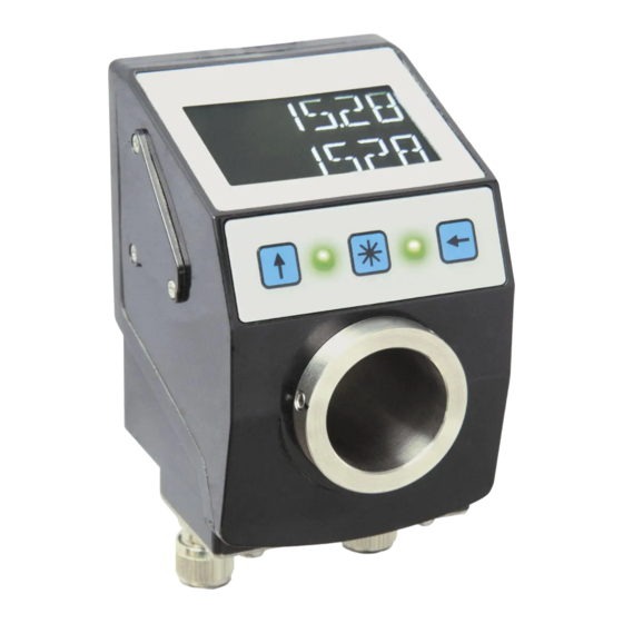
Absolute / elektronische positionsanzeige
Vorschau ausblenden
Andere Handbücher für AP10:
- Benutzerhandbuch (78 Seiten) ,
- Originalmontageanleitung (44 Seiten) ,
- Originalbetriebsanleitung (40 Seiten)

Verwandte Anleitungen für Siko AP10


Inhaltszusammenfassung für Siko AP10
- Seite 1 AP10 Absolute / elektronische Positionsanzeige Deutsch Originalmontageanleitung Seite 2 Absolute / Electronic Position Indicator English Translation of the Original Installation Instructions page 20 356/14...
-
Seite 2: Inhaltsverzeichnis
6.4 Störung nach Batteriewechsel 7 Transport, Lagerung, Wartung und Entsorgung 8 Zubehör Anschluss-Stecker 8.1 Gegenstecker M8 gerade 8.2 Gegenstecker M8 BUS-Abschluss 8.3 Gegenstecker M8 gerade inkl. Kabel 9 Technische Daten AP10 · Datum 25.09.2014 · Art. Nr. 86832 · Änd. Stand 356/14... -
Seite 3: Dokumentation
Sicherheitshinweise bestehen aus dem Signalzeichen und einem Signal- wort. Gefahrenklassen Unmittelbare Gefährdungen die zu schweren irreversiblen Körperverlet- GEFAHR zungen mit Todesfolge, Sachschäden oder ungeplanten Gerätereaktionen führen können, sofern Sie die gegebenen Anweisungen missachten. AP10 · Datum 25.09.2014 · Art. Nr. 86832 · Änd. Stand 356/14... -
Seite 4: Zielgruppe
Automatisierungstechnik vertraut sind; • als Inbetriebnahme und Monatagepersonal berechtigt sind, Strom- kreise und Geräte/Systeme gemäß den Standards der Sicherheitstech- nik in Betrieb zu nehmen, zu erden und zu kennzeichnen. AP10 · Datum 25.09.2014 · Art. Nr. 86832 · Änd. Stand 356/14... -
Seite 5: Grundlegende Sicherheitshinweise
Welle und Aufnahmebohrungen durch geeignete Fertigungsmaßnah- Abb. 1 Tab. men (siehe Zerstörung Positionsanzeige VORSICHT Starke Schmutzbelastung führt zu einer Reduktion der Lebensdauer des Hauptlagers. ` Schmutzbelastung durch Schutzmaßnahmen (z. B. V-Ring) verhin- dern. AP10 · Datum 25.09.2014 · Art. Nr. 86832 · Änd. Stand 356/14... - Seite 6 Maß ød ø6 (Form A) ø10 (Form B) +0.8 Maß L1 22 oder 30 (±0.1 bei Form A) Maß øD ø20 (Spielpassung) Abb. 1: Einbaumaße Tab. 1: Einbaumaße AP10 · Datum 25.09.2014 · Art. Nr. 86832 · Änd. Stand 356/14...
-
Seite 7: Elektrische Installation
WARNUNG Zum Schutz von Folgeschäden bei Gerätedefekten wird eine Absicherung empfohlen. ` Die Nennstromstärke einer trägen Sicherung muss der Geräteanzahl im System entsprechend angepasst sein (siehe Kapitel 9). AP10 · Datum 25.09.2014 · Art. Nr. 86832 · Änd. Stand 356/14... - Seite 8 Für die Funktion des Feldbusses ist an beiden Busenden je ein Abschluss- widerstand notwendig (120 Ohm). Dieser muss zwischen CANH und CANL eingesetzt werden. Abb. 4: Terminierung CAN AP10 · Datum 25.09.2014 · Art. Nr. 86832 · Änd. Stand 356/14...
- Seite 9 Belegung Bus-Ein Bus-Aus DÜB/TxRx-/CANL DÜA/TxRx+/CANH Ansichtseite = Steckseite Bus EIN Bus AUS PE Anschluss Abb. 6: Anschlussbelegung AP10 · Datum 25.09.2014 · Art. Nr. 86832 · Änd. Stand 356/14...
- Seite 10 6). Verwenden Sie dazu 6.3 mm Flachstecker mit kurzer Litze 2.5 mm² … 4 mm² (nicht im Lieferumfang). Bei mehreren Positionsanzeigen wird Abb. empfohlen die Erdung auf eine PE-Schiene anzuschließen (siehe Abb. 7: PE-Schiene AP10 · Datum 25.09.2014 · Art. Nr. 86832 · Änd. Stand 356/14...
-
Seite 11: Inbetriebnahme
- Taste schaltet die Kettenmaß-Funktion ein- bzw. aus. • Das Drücken der - Taste startet die Kalibrierung (siehe Benutzer- handbuch). • Das Drücken der - Taste startet den Parametrier-/Programmiermo- dus (siehe Benutzerhandbuch). AP10 · Datum 25.09.2014 · Art. Nr. 86832 · Änd. Stand 356/14... - Seite 12 1 ... 127 Bus-Adresse ACHTUNG Nach Änderung des Parame- ters muss ein Neustart durch- geführt werden! bAUd 125, 250, 500, Auto CAN Baudrate (z. B. 800, 1000kbd, 250 kbit/s) Auto AP10 · Datum 25.09.2014 · Art. Nr. 86832 · Änd. Stand 356/14...
-
Seite 13: Kapitel 5.1) Werkseinstellungen Laden
2. Kalibrierung (Reset) durchführen (siehe Kapitel 5: Anzeige und Bedientasten) => Positionswert = 0 + Kalibrierwert + Offsetwert Eine Kalibrierung ist aufgrund des absoluten Messsystems nur einmal bei der Inbetriebnahme erforderlich. AP10 · Datum 25.09.2014 · Art. Nr. 86832 · Änd. Stand 356/14... -
Seite 14: Batteriewechsel
Austausch kann bei SIKO-Vertriebspartnern, im SIKO-Stammwerk oder selbst durchgeführt werden. 6.2 Betriebszustand Batteriesymbol blinkt: Batterie nahezu leer Im Standardbetrieb dauert es noch ~3 Monate bis die Batterie vollständig entladen ist. Batteriesymbol leuchtet: Batterie erneuern AP10 · Datum 25.09.2014 · Art. Nr. 86832 · Änd. Stand 356/14... -
Seite 15: Austausch Der Batterieeinheit
2. Korrekte Lage des O-Rings überprüfen. O-Ring muss bei der Mon- tage der Batterieeinheit umlaufend am Batteriegehäuse auflie- gen. Schrauben Batterieeinheit O-Ring Gehäuse Abb. 9: Batteriewechsel AP10 · Datum 25.09.2014 · Art. Nr. 86832 · Änd. Stand 356/14... -
Seite 16: Störung Nach Batteriewechsel
Die Umweltrichtlinien des jeweiligen Landes müssen hierzu beachtet werden. Batterie: Werfen Sie Batterien nicht in den normalen Müll, ins Feuer oder ins Wasser. Batterien sollen gesammelt und auf umweltfreundliche Weise entsorgt werden. AP10 · Datum 25.09.2014 · Art. Nr. 86832 · Änd. Stand 356/14... -
Seite 17: Zubehör Anschluss-Stecker
6. Isolierschlauch auffädeln, Litzen anlöten und Isolierschlauch mon- tieren. 7. Kupplungshülse mit Einsatz verschrauben und Druckschraube festdrehen. Abb. 10: Gegenstecker M8 gerade AP10 · Datum 25.09.2014 · Art. Nr. 86832 · Änd. Stand 356/14... -
Seite 18: Gegenstecker M8 Bus-Abschluss
(LED hinterleuchted rot/weiß) Sonderzeichen Pfeil Uhrzeigersinn, Pfeil Gegenuhrzeigersinn, Ketten- maß, Batterie Statusanzeige 2x zweifarbige LED (rot/grün) Positionsstatus, parametrierbar Tasten Kettenmaßfunktion, Parame- trieren, Rücksetzen Busanschluss RS485; CANopen keine galvanische Trennung AP10 · Datum 25.09.2014 · Art. Nr. 86832 · Änd. Stand 356/14... - Seite 19 Umgebungsbedingungen Ergänzung Umgebungstemperatur 0 … 60 °C Lagertemperatur -20 … 80 °C relative Luftfeuchtigkeit Betauung nicht zulässig Schutzart IP53 EN 60529, nur mit Gegenstecker IP65 EN 60529, nur mit Gegenstecker AP10 · Datum 25.09.2014 · Art. Nr. 86832 · Änd. Stand 356/14...
- Seite 37 AP10...
- Seite 38 AP10...
- Seite 39 AP10...
- Seite 40 SIKO GmbH Weihermattenweg 2 79256 Buchenbach Telefon/Phone + 49 7661 394-0 Telefax/Fax + 49 7661 394-388 E-Mail info@siko.de Internet www.siko-global.com Service support@siko.de...