Gemü 610 Einbau- Und Montageanleitung
Vorschau ausblenden
Andere Handbücher für 610:
- Betriebsanleitung (64 Seiten) ,
- Original einbau- und montageanleitung (36 Seiten) ,
- Originalbetriebsanleitung (36 Seiten)

Verwandte Anleitungen für Gemü 610


Inhaltszusammenfassung für Gemü 610
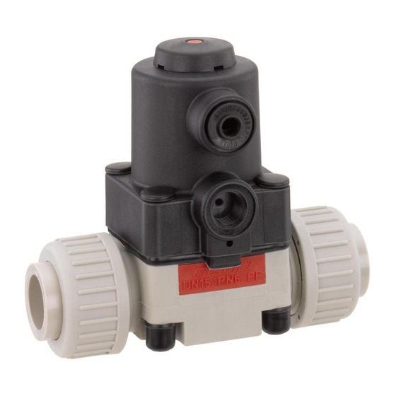
- Seite 1 Membranventil Kunststoff , DN 12 - 20 Diaphragm Valve Plastic, DN 12 - 20 ORIGINAL EINBAU- UND MONTAGEANLEITUNG INSTALLATION, OPERATING AND MAINTENANCE INSTRUCTIONS...
-
Seite 2: Inhaltsverzeichnis
Inhaltsverzeichnis Allgemeine Hinweise Voraussetzungen für die einwandfreie Allgemeine Hinweise Funktion des GEMÜ-Ventils: Allgemeine Sicherheitshinweise 2 Sachgerechter Transport und Lagerung Hinweise für Service- Installation und Inbetriebnahme durch und Bedienpersonal eingewiesenes Fachpersonal Warnhinweise Bedienung gemäß dieser Einbau- und Verwendete Symbole Montageanleitung Begriff sbestimmungen Ordnungsgemäße Instandhaltung Vorgesehener Einsatzbereich Auslieferungszustand... -
Seite 3: Hinweise Für Service
Hinweise für Service- Warnhinweise und Bedienpersonal Warnhinweise sind, soweit möglich, nach folgendem Schema gegliedert: Die Einbau- und Montageanleitung enthält grundlegende Sicherheitshinweise, die bei SIGNALWORT Inbetriebnahme, Betrieb und Wartung zu beachten sind. Nichtbeachtung kann zur Art und Quelle der Gefahr Folge haben: ®... -
Seite 4: Verwendete Symbole
Vorgesehener Verwendete Symbole Einsatzbereich Gefahr durch heiße Oberfl ächen! Das GEMÜ-Ventil 610 ist für den Einsatz in Rohrleitungen konzipiert. Es steuert ein Gefahr durch ätzende Stoff e! durchfl ießendes Medium indem es durch ein Steuermedium geschlossen oder geöff net werden kann. -
Seite 5: Technische Daten
Technische Daten Betriebsmedium Umgebungstemperatur Aggressive, neutrale, gasförmige und flüssige Medien, die Ventilkörper PVC-U 10 bis 50 °C die physikalischen und chemischen Eigenschaften des Ventilkörper PP / PP-H 5 bis 50 °C jeweiligen Gehäuse- und Membranwerkstoffes nicht negativ Ventilkörper PVDF -5 bis 50 °C beeinflussen. -
Seite 6: Bestelldaten
Bestelldaten Gehäuseform Code Steuerfunktion Code Durchgang Federkraft geschlossen (NC) Federkraft geöffnet (NO) Beidseitig angesteuert (DA) Anschlussart Code Gewindemuffe DIN ISO 228 Antriebsgröße Code Klebemuffe DIN Membrangröße 10 Armaturenverschraubung mit Einlegeteil DIN (Muffe) Steuermediumanschluss 90° zur Durchflussrichtung Stutzen zum IR-Stumpfschweißen, WNF Membrangröße 10 Armaturenverschraubung mit Einlegeteil Zoll - BS (Muffe) 33 Steuermediumanschluss in Durchflussrichtung... -
Seite 7: Herstellerangaben
Herstellerangaben Funktionsbeschreibung GEMÜ 610 ist ein Kunststoff -Membranventil Transport mit Durchgangskörper. Das Ventil besitzt einen wartungsarmen Kolbenantrieb, Ventil nur auf geeignetem Lademittel der mit neutralen Gasen angesteuert transportieren, nicht stürzen, vorsichtig werden kann, und eine integrierte optische handhaben. Stellungsanzeige. Alle mediumsberührten Verpackungsmaterial entsprechend Teile und das Antriebsgehäuse sind aus... -
Seite 8: Montage Und Bedienung
Montage und Bedienung Installationsort: VORSICHT Vor Einbau: Eignung Ventilkörper- und Ventil äußerlich nicht stark Membranwerkstoff entsprechend beanspruchen. Betriebsmedium prüfen. Installationsort so wählen, dass Ventil Siehe Kapitel 6 "Technische Daten". nicht als Steighilfe genutzt werden kann. Rohrleitung so legen, dass Schub- und 11.1 Montage des Ventils Biegungskräfte, sowie Vibrationen... - Seite 9 Montage bei Armaturenverschraubung Montage bei Gewindeanschluss: mit Einlegeteil: Gewindeanschlüsse entsprechend der gültigen Normen in Rohr einschrauben. VORSICHT Ventilkörper an Rohrleitung anschrauben, Beschädigungen am Ventilantrieb oder geeignetes Gewindedichtmittel Ventilkörper! verwenden. Das Gewindedichtmittel ist ® Schweißtechnische Normen einhalten! nicht im Lieferumfang enthalten. VORSICHT Montage bei Klebemuff...
-
Seite 10: Bedienung
11.2 Bedienung Optische Stellungsanzeige Anschluss 4 Anschluss 2 Bei Steuerfunktion 1 ist der Anschluss 4 mit Ventil off en Ventil geschlossen einem Blindstopfen verschlossen. Bei Steuerfunktion 2 ist der Anschluss 2 mit 11.3 Steuerfunktionen einem Blindstopfen verschlossen. Folgende Steuerfunktionen sind verfügbar: Anschlüsse Steuerfunktion Steuerfunktion 1... -
Seite 11: Montage / Demontage Von Ersatzteilen
Montage / Demontage 12.3 Montage Membrane von Ersatzteilen 12.3.1 Allgemeines Wichtig: Für Ventil passende Membrane einbauen (geeignet für Medium, Mediumkonzentration, Temperatur und Druck). Die Absperrmembrane ist ein Verschleißteil. Vor Inbetriebnahme und über gesamte Einsatzdauer des Ventils technischen Zustand und Funktion überprüfen. -
Seite 12: 12.3.2 Montage Der Konkav-Membrane
Das Druckstück ist lose. einpassen (siehe Kapitel 12.3.1 "Allgemeines"). Steuerfunktion NO Druckstück und Antriebsfl ansch von unten und DA: prüfen ob die Stifte in die gesehen: Verdrehsicherung eingerastet sind. 3. Kontrollieren ob das Druckstück in den Führungen liegt. 4. Neue Membrane von Hand fest in Druckstück einschrauben. -
Seite 13: Inbetriebnahme
Inbetriebnahme Inspektion und Wartung WARNUNG WARNUNG Aggressive Chemikalien! Unter Druck stehende Armaturen! ® Verätzungen! ® Gefahr von schwersten Verletzungen Vor Inbetriebnahme Dichtheit oder Tod! der Medienanschlüsse Nur an druckloser Anlage arbeiten. prüfen! VORSICHT Dichtheitsprüfung nur mit geeigneter Heiße Anlagenteile! Schutzausrüstung. ®... -
Seite 14: Demontage
Demontage Hinweise Demontage erfolgt unter den gleichen Hinweis zur Vorsichtsmaßnahmen wie die Montage. Mitarbeiterschulung: Ventil demontieren (siehe Kapitel 12.1 Zur Mitarbeiterschulung nehmen "Demontage Ventil (Antrieb vom Körper Sie bitte über die Adresse auf der lösen)"). letzten Seite Kontakt auf. Im Zweifelsfall oder bei Missverständnissen Entsorgung ist die deutsche Version des Dokuments ausschlaggebend! -
Seite 15: Fehlersuche / Störungsbehebung
Fehlersuche / Störungsbehebung Fehler Möglicher Grund Fehlerbehebung Steuermedium entweicht aus Anschluss 4* (bei Steuerfunktion NC) Antriebskolben defekt Antrieb austauschen bzw. Anschluss 2* (bei Steuerfunktion NO) Steuermedium entweicht Antrieb austauschen und Steuermedium auf Spindelabdichtung undicht aus Leckagebohrung* Verschmutzungen untersuchen Betriebsmedium Absperrmembrane auf Beschädigungen prüfen, entweicht aus Absperrmembrane defekt ggf. -
Seite 16: Schnittbild Und Ersatzteile
Schnittbild und Ersatzteile Anschluss 4 Anschluss 2 Leckagebohrung Pos. Benennung Bestellbezeichnung Ventilkörper O-Ring K610... Einlegeteil Überwurfmutter Membrane 600 10M... Schraube Scheibe Abdeckkappe 610...S30... Abdeckkappe Mutter Antrieb 9610 10... 16 / 36... -
Seite 17: Einbauerklärung
29.12.2009 Projektnummer: MV-Pneum-2009-12 Handelsbezeichnung: Typ 610 Es wird erklärt, dass die folgenden grundlegenden Anforderungen der Maschinenrichtlinie 2006/42/EG erfüllt sind: 1.1.3.; 1.1.5.; 1.1.7.; 1.2.1.; 1.3.; 1.3.2.; 1.3.3.; 1.3.4.; 1.3.7.; 1.3.9.; 1.5.3.; 1.5.5.; 1.5.6.; 1.5.7.; 1.5.8.; 1.5.9.; 1.6.5.; 2.1.1.; 3.2.1.; 3.2.2.; 3.3.2.; 3.4.4.; 3.6.3.1.; 4.1.2.1.; 4.1.2.3.; 4.1.2.4.; 4.1.2.5.; 4.1.2.6. a); 4.1.2.6. b);... - Seite 34 34 / 36...
- Seite 35 35 / 36...
- Seite 36 GEMÜ Gebr. Müller Apparatebau GmbH & Co. KG · Fritz-Müller-Str. 6-8 · D-74653 Ingelfi ngen-Criesbach Telefon +49(0)7940/123-0 · Telefax +49(0)7940/123-192 · info@gemue.de · www.gemu-group.com...