WIKA DI25 Betriebsanleitung
Inhaltsverzeichnis
Quicklinks
Inhaltsverzeichnis

Verwandte Anleitungen für WIKA DI25


Inhaltszusammenfassung für WIKA DI25
- Seite 1 DIGITAL INDICATOR DI25 Operating instructions...
-
Seite 2: Safety Precautions
• Measures must be taken to ensure that the operator cannot touch power terminals or other high voltage sections. • Any unauthorized transfer or copying of this document, in part or in whole, is prohibited. • WIKA is not liable for any damage or secondary damage(s) incurred as a result of using this product, including any indirect damage. -
Seite 3: Installation Precautions
Caution with respect to export trade control ordinance To avoid this instrument from being used as a component in, or as being utilized in the manufacture of weapons of mass destruction (i.e. military applications, military equipment, etc.), please investigate the end users and the final use of this instrument. - Seite 4 • As the display section is vulnerable, be careful not to put pressure on, scratch or strike it with a hard object. Further information: Internet address: www.wika.de / www.wika.com Relevant data sheet: AC 80.02 Application consultant: Tel.: +49 9372 132-0 Fax: +49 9372 132-406 info@wika.de...
- Seite 5 Contents 1. Model ..............................1.1 Model ............................1.2 Product label ..........................2. Display and controls ........................3. Control panel mounting ........................3.1 External dimensions in mm ......................3.2 Panel cutout in mm ........................3.3 Mounting the unit ........................4. Wiring ..............................4.1 Terminal arrangement .........................
- Seite 6 1. Model Model DI25 - M Series name: DI25 (W 96 x H 48 x D 100 mm) □, □□□□□ Input Multi-function input (*1) 100 … 240 V AC Power supply 24 V AC/DC 3 alarm outputs for process value monitoring (*2) Output options Transmitter supply output (DC 24 V max.
-
Seite 7: Display And Controls
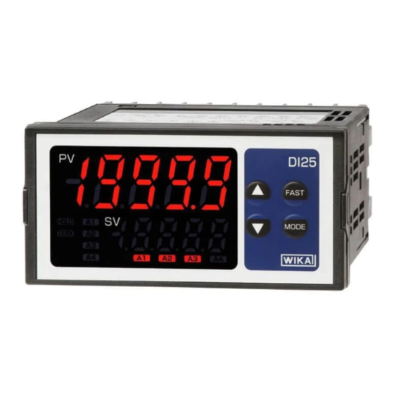
2. Display and Controls FAST key UP key PV display SV display HOLD indicator TX/RX indicator A1 to A4 value indicator A1 to A4 action indicator DOWN key MODE key (Fig. 2-1) Display, indicator Name Description PV display Indicates PV (process variable) or characters in the setting mode with the red LED. SV display Indicates A1/A2/A3 value or the set value in the setting mode with the green LED. -
Seite 8: External Dimensions In Mm
(2) Attach the mounting brackets by the slots on the right and left sides of the case, and secure the instrument in place with the screws. (Fig. 3.4-1) Caution As the case of the DI25 is made of resin, do not use excessive force while tightening screws, or the mounting brackets or case could be damaged. 0.12 Nm of torque is recommended. -
Seite 9: Terminal Arrangement
4. Wiring Warning Turn the power supply to the instrument off before wiring or checking. Working on or touching the terminal with the power switched on may result in severe injury or death due to electrical shock. Terminal arrangement (Fig. 4.1-1) Terminal name Description Ground terminal... - Seite 10 Using as a crrent loop supply Refer to the following wiring example. 24 V power circuit (Fig. 4.3-1) 2-wire transmitter 5. Setup After power is turned ON, the input characters and temperature unit will be indicated on the PV display, and the input range high limit (for thermocouple, RTD input) or scaling high limit (for direct current, DC voltage input) will be indicated on the SV display for approx.
-
Seite 11: Alarm Setting Mode
Registering the selected item or value • To increase or decrease the numeric value, use the UP or DOWN key. o To make the set value change faster, press and hold the UP/DOWN key and FAST key together. o Select an setting item with the UP or DOWN key. •... - Seite 12 Character factory default Setting item, function, setting range Sensor correction • This corrects the input value from the sensor. When a sensor cannot be set at the exact location where measurement is desired, the sensor-measured temperature may deviate from the temperature in the measurement location.
- Seite 13 (7) Set step (6) value as a sensor correction value. (8) Enter an electromotive force or resistance value equivalent to 750 using an mV generator or dial resistor. (9) Read the PV, and confirm that 700 is indicated. Auxiliary function setting mode 2 To enter auxiliary function setting mode 2, press and hold the UP, DOWN and MODE keys (in that order) together for approx.
- Seite 14 Character factory default Setting item, function, setting range Scaling high limit • Sets scaling high limit value. • Available when DC current or DC voltage input is selected in [Input type]. • Setting range: Scaling low limit to Input range high limit (the placement of the decimal point follows the selection or input range.) Scaling low limit •...
- Seite 15 Character factory default Setting item, function, setting range A1 Energized/De-energized • Selects A1 Energized/De-energized. Not available if no alarm action is selected in [A1 type]. • When [A1 Energized] is selected, A1 output (terminals 7, 8) is conducted (ON) while A1 action indicator is lit. A1 output is not conducted (OFF) while A1 action indicator is unlit.
- Seite 16 Character factory default Setting item, function, setting range A3 hysteresis • Sets A3 hysteresis. • Not available if no alarm action or high/low limit range alarm is selected in [A3 type]. • Setting range: 0.1 to 100.0 DC current, DC voltage input: 1 to 1000 (the placement of the decimal point follows the selection.) A1 delay time •...
- Seite 17 Character factory default Setting item, function, setting range Event input function • Selects event input function. • (HOLD): PV at the given time is held and indicated by closing event input terminals (14, 17). The HOLD function is cancelled by opening the event input terminals (14, 17).
-
Seite 18: Maintenance Mode
Character factory default Setting item, function, setting range • The FAST key is pressed for approx. 3 seconds. • The power is turned OFF. • The HOLD is cancelled by the event input function. During A3 HOLD, the A3 action indicator flashes. : Disabled : Enabled Square root function... - Seite 19 After the DI25 is mounted to the control panel and wiring is completed, operate the unit following the procedure below. (1) Turn the power supply to the DI25 ON. For approximate 3 sec after the power is switched ON, the input characters and the temperature unit are indicated on the PV Display, and input range high limit (thermocouple, RTD input) or scaling high limit (direct current, DC voltage input) is indicated on the SV display.
- Seite 20 7. Alarm action High limit alarm, low limit alarm High limit alarm Low limit alarm A 1 hysteresis A 1 hysteresis A 1 action A 1 value A 1 value A 1 output High limit with standby alarm Low limit with standby alarm A 1 hysteresis A 1 hysteresis A 1 action...
-
Seite 21: Please Note The Following
7.2 A3 High/Low limit range alarm action High/Low limit range alarm [Low limit alarm] [High limit alarm] A1 (A2) hysteresis A2 (A1) hysteresis A1, A2, A3 action A1 (A2) value A2 (A1) A2 (A1) value A1 (A2) hysteresis hysteresis value value [High/Low limit range alarm] A3 action... - Seite 22 8. Specifications Dimensions 96 x 48 x 100 mm (W x H x D) Mounting Flush (mountable panel thickness: 1 to 8 mm) Material Case: Polycarbonate, color: black Ingress protection Front: IP66, back: IP00 Setting method Input system using membrane sheet key Display PV display: red LED 4½-digits, character size, 16 x 7.2 mm (H x W) SV display: green LED 4½-digits, character size, 10 x 4.8 mm (H x W)
- Seite 23 Attached function Burnout When the thermocouple or RTD input is burnt out, the PV Display flashes Input error indication Indication Contents flashes. Overscale: Measured value has exceeded indication range high limit. Underscale: Measured value has dropped below indication range low flashes.
- Seite 24 For further specifications see WIKA data sheet AC 80.02. 9. Troubleshooting If any malfunction occurs, refer to the following items after checking that power is being supplied to the DI25. Problem Possible cause Solution Internal memory is defective.
- Seite 25 Problem Possible cause Solution display Check whether the input signal How to check whether the input signal wire is keeps indicating wires of DC voltage (0 to 5 V disconnected the value set in DC, 0 to 10 V DC) and direct [DC voltage (0 to 5 V DC, 0 to 10 V DC)] [Scaling low limit].
- Seite 26 10. Flow diagram for the programming levels Power ON [About setting item] PV/SV display mode • Upper left: PV Display: Indicates the setting item characters. A1 value is A1 value • Lower left: SV Display: Indicates the factory default. Right side: Setting item A1 value displayed.
-
Seite 27: Dismounting, Return And Disposal
Strictly observe the following when shipping the instrument: All instruments delivered to WIKA must be free from any kind of hazardous substances (acids, bases, solutions, etc.) and must therefore be cleaned before being returned. When returning the instrument, use the original packaging or a suitable transport packaging. - Seite 28 14076218.02 05/2018 EN...