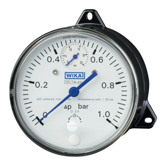
WIKA DELTA-plus DPG40 Betriebsanleitung
Differenzdruckmessgeräte delta-line
Vorschau ausblenden
Andere Handbücher für DELTA-plus DPG40:
- Bedienungsanleitung (20 Seiten) ,
- Betriebsanleitung (60 Seiten)

Verwandte Anleitungen für WIKA DELTA-plus DPG40


Inhaltszusammenfassung für WIKA DELTA-plus DPG40
- Seite 25 Inhalt Inhalt Allgemeines Sicherheit Technische Daten Aufbau und Funktion Transport, Verpackung und Lagerung Inbetriebnahme, Betrieb Optionen und Zubehör Wartung Demontage, Rücksendung und Entsorgung Anlage: Konformitätserklärungen Konformitätserklärungen finden Sie online unter www.wika.de. WIKA Betriebsanleitung DELTA-plus, DELTA-comb und DELTA-switch...
-
Seite 26: Allgemeines
… weist auf eine möglicherweise gefährliche Situation hin, die zum Tod oder zu schweren Verletzungen führen kann, wenn sie nicht gemieden wird. Information … hebt nützliche Tipps und Empfehlungen sowie Informationen für einen effizienten und störungsfreien Betrieb hervor. WIKA Betriebsanleitung DELTA-plus, DELTA-comb und DELTA-switch... -
Seite 27: Sicherheit
Steuerung von Filtern, Kompressoren und Pumpen. Das Gerät ist ausschließlich für den hier beschriebenen bestimmungsgemäßen Verwendungszweck konzipiert und konstruiert und darf nur dementsprechend verwendet werden. Ansprüche jeglicher Art aufgrund von nicht bestimmungsgemäßer Verwendung sind ausgeschlossen. WIKA Betriebsanleitung DELTA-plus, DELTA-comb und DELTA-switch... -
Seite 28: Personalqualifikation
WARNUNG! Messstoffreste in ausgebauten Messgeräten können zur Gefährdung von Personen, Umwelt und Einrichtung führen. Ausreichende Vorsichtsmaßnahmen ergreifen. WARNUNG! Die maximale Oberflächentemperatur des Gerätes darf die Zündtemperatur brennbarer Messstoffe nicht überschreiten. Ausreichende Vorsichtsmaßnahmen ergreifen. WIKA Betriebsanleitung DELTA-plus, DELTA-comb und DELTA-switch... -
Seite 29: Beschilderung, Sicherheitskennzeichnungen
Geräte mit dieser Kennzeichnung stimmen überein mit den zu- treffenden europäischen Richtlinien. Verbrennungsgefahr! Möglicherweise gefährliche Situation durch heiße Oberflächen. Aufgrund der maximal zulässigen Prozesstemperatur von 90 °C können Messzellen, Anschlussstücke, Ventile oder sonstige Anbauteile eine Temperatur von 90 °C erreichen. WIKA Betriebsanleitung DELTA-plus, DELTA-comb und DELTA-switch... -
Seite 30: Technische Daten
Achsabstand 26 mm Messglieder Differenzdruck: Druckfedern aus CrNi-Stahl 1.4310 und (messstoffberührt) Trennmembrane aus FPM/FKM (Option: NBR) Betriebsdruck: Rohrfeder aus Cu-Legierung Übertragungsteile CrNi-Stahl 1.4301, 1.4305, 1.4310, FPM/FKM (Option: (messstoffberührt) NBR) FPM/FKM (Option: NBR) Dichtungen (messstoffberührt) Zeigerwerk Kupferlegierung WIKA Betriebsanleitung DELTA-plus, DELTA-comb und DELTA-switch... - Seite 31 Trennmembrane aus FPM/FKM (Option: NBR) Übertragungsteile CrNi-Stahl 1.4301, 1.4305, 1.4310, FPM/FKM (Option: NBR) (messstoffberührt) Dichtungen (messstoff- FPM/FKM (Option: NBR) berührt) Gehäuse Aluminium, EN AC–Al Si9Cu3(Fe), schwarz lackiert Sichtscheibe Kunststoff, mit Verschlussschraube zur Schaltpunktverstellung Gewicht ca. 1,4 kg WIKA Betriebsanleitung DELTA-plus, DELTA-comb und DELTA-switch...
-
Seite 32: Elektrischer Kontakt
5 % vom Skalenendwert (Option: max. 2,5 %) Elektrischer Anschluss Kabelverschraubung M20 x 1,5 mit 1 m freiem Kabel Weitere technische Daten siehe jeweiliges Typenschild, WIKA-Datenblatt und Bestellunterlagen Für Typen mit optionalem Explosionsschutz „Zusatzinformation für explosions- gefährdete Bereiche (Ex i), Typen DPS40, DPGS40, DPGS40TA und DPGT40”, Artikelnummer 14110818 lesen. -
Seite 33: Aufbau Und Funktion
Der dem Differenzdruck proportionale Messweg wird über einen Kipphebel (3) druckdicht und reibungsarm in das Anzeigegehäuse auf das Zeigerwerk (4) übertragen. Die Überlastsicherheit wird durch Anlage der elastischen Membrane an metallische Stützflächen (5) erreicht. ⊖ ⊕ WIKA Betriebsanleitung DELTA-plus, DELTA-comb und DELTA-switch... - Seite 34 Die Überlastsicherheit wird durch Anlage der elastischen Membrane an metallische Stützflächen (6) erreicht. Die Schaltpunktverstellung erfolgt über die frontseitig zugänglichen Einstell- schrauben (7). Die Hilfsskalen (8) erleichtern die Schaltpunkteinstellung. ⊖ ⊕ WIKA Betriebsanleitung DELTA-plus, DELTA-comb und DELTA-switch...
-
Seite 35: Lieferumfang
Stützflächen (5) erreicht. Die Schaltpunktverstellung erfolgt über die frontseitig zugänglichen Einstell- schrauben (6). Die Hilfsskalen (7) erleichtern die Schaltpunkteinstellung. ⊖ ⊕ 4.2 Lieferumfang Lieferumfang mit dem Lieferschein abgleichen. WIKA Betriebsanleitung DELTA-plus, DELTA-comb und DELTA-switch... -
Seite 36: Transport, Verpackung Und Lagerung
Explosionsgefährdete Umgebung, entzündliche Atmosphäre ■ WARNUNG! Vor der Einlagerung des Gerätes müssen alle ggf. anhaftenden Messstoffreste entfernt werden. Dies ist besonders wichtig, wenn das Medium gesundheitsgefährdend ist, wie z. B. ätzend, giftig, krebserregend, radioaktiv, usw. WIKA Betriebsanleitung DELTA-plus, DELTA-comb und DELTA-switch... -
Seite 37: Inbetriebnahme, Betrieb
Zur Abdichtung der Anschlüsse sind Flachdichtungen, Dichtlinsen oder ■ WIKA-Profildichtungen einzusetzen. Um das Gerät in die Stellung zu bringen, in der sich die örtliche Anzeige am besten ablesen lässt, ist ein Anschluss mit Spannmuffe oder Überwurfmutter zu empfehlen. Beim Ein- und Ausschrauben dürfen die Geräte nicht am Gehäuse angezogen werden, sondern nur an den... -
Seite 38: Temperaturbelastung
Geräten selbst abhängig, sondern hauptsächlich von der jeweiligen Messstofftemperatur! Bei gasförmigen Stoffen kann sich die Temperatur durch Kompressionswärme erhöhen. In solchen Fällen muss ggf. die Druckänderungsgeschwindigkeit gedrosselt bzw. die zulässige Messstofftemperatur reduziert werden. WIKA Betriebsanleitung DELTA-plus, DELTA-comb und DELTA-switch... - Seite 39 (feucht) densiert Beispiele Kondensat siedende „Flüssig- trockene feuchte Luft Wasser- Flüssig- gase“ Luft Rauchgase dampf keiten Manometer oberhalb des Entnahme- stutzens Manometer unterhalb des Entnah- mestutzens Abmessungen in mm DELTA-plus Typ DPG40 WIKA Betriebsanleitung DELTA-plus, DELTA-comb und DELTA-switch...
- Seite 40 6. Inbetriebnahme, Betrieb DELTA-comb Typ DPGS40 Kabelverschraubung M20 x 1,5 mit 1 m Kabel DELTA-switch Typ DPS40 Kabelverschraubung M20 x 1,5 mit 1 m Kabel WIKA Betriebsanleitung DELTA-plus, DELTA-comb und DELTA-switch...
-
Seite 41: Elektrischer Anschluss (Betrifft Typen Delta-Comb Und Delta-Switch)
Die vorgesehenen Netzanschlussleitungen müssen für die größte Stromauf- ■ nahme des Gerätes bemessen sein und IEC 227 oder IEC 245 entsprechen. Die Geräte sind in den Potenzialausgleich der Anlage mit einzubeziehen. ■ Leistungsdaten (siehe Kapitel 3 „Technische Daten“) WIKA Betriebsanleitung DELTA-plus, DELTA-comb und DELTA-switch... -
Seite 42: Sicherheitshinweise Bei Installation
1. Kontakt Kabelanschlussdose Information Für den Sicherheitsstromkreis, der bei Unterschreiten des Mindestdurchflusses die Beheizung des Dampferzeugers abschalten soll, darf nur der Schließer des Umschaltkontaktes angeschlossen werden (d. h. der bei Δp = 0 offene Kreis)! WIKA Betriebsanleitung DELTA-plus, DELTA-comb und DELTA-switch... - Seite 43 Anschlussleitungen müssen für den Umgebungstemperaturbereich der ■ Applikation geeignet sein. Kabeleinführung mit den entsprechend zugelassenen Kabelverschraubungen ■ dicht verschließen. Ausführung der Kabelverschraubung Nur Kabel mit Durchmesser 7 ... 13 mm verwenden Anschlusskabel fest verlegen. ■ WIKA Betriebsanleitung DELTA-plus, DELTA-comb und DELTA-switch...
-
Seite 44: Optionen Und Zubehör
Prozess sowie Vermeidung einseitiger Überdruckbelastung während der Anfahr- bzw. Betriebsphase (bei geöffnetem Druckausgleichsventil). Entlüftung der Messleitungen bei flüssigen ■ Messstoffen und Spülung der Messlei- Entlüftungs- Absperrventil ⊖ -Seite ventil tungen, um Verunreinigungen zu entfernen. WIKA Betriebsanleitung DELTA-plus, DELTA-comb und DELTA-switch... -
Seite 45: Befestigungsrand Für Schalttafelmontage
1. Druckausgleichsventil öffnen 2. Absperrventil der ⊕- und ⊖-Messstoffkammer schließen Arbeitsgangfolge zur Demontage des Messgerätes bei laufenden Prozess ■ 1. Absperrventil der ⊕- und ⊖-Messstoffkammer schließen 2. Entlüftungsventil öffnen 7.2 Befestigungsrand für Schalttafelmontage Schalttafel WIKA Betriebsanleitung DELTA-plus, DELTA-comb und DELTA-switch... -
Seite 46: Wartung
Ausgebautes Messgerät vor der Rücksendung spülen bzw. säubern, um Mitarbeiter und Umwelt vor Gefährdung durch anhaftende Messstoffreste zu schützen. 9.3 Entsorgung Durch falsche Entsorgung können Gefahren für die Umwelt entstehen. Gerätekomponenten und Verpackungsmaterialien entsprechend den landesspezifischen Abfallbehandlungs- und Entsorgungsvorschriften umweltgerecht entsorgen. WIKA Betriebsanleitung DELTA-plus, DELTA-comb und DELTA-switch... - Seite 52 WIKA subsidiaries worldwide can be found online at www.wika.com. WIKA-Niederlassungen weltweit finden Sie online unter www.wika.de. WIKA Alexander Wiegand SE & Co. KG Alexander-Wiegand-Straße 30 63911 Klingenberg • Germany Tel. +49 9372 132-0 Fax +49 9372 132-406 info@wika.de www.wika.de WIKA operating instructions DELTA-plus, DELTA-comb and DELTA-switch...