WIKA DELTA-comb DPGS40TA Betriebsanleitung
Inhaltsverzeichnis
Verfügbare Sprachen
Verfügbare Sprachen
Quicklinks
Differential pressure gauge with micro switches,
model DPGS40TA, with component testing
Differenzdruckmanometer mit Mikroschaltern,
Typ DPGS40TA, mit Bauteilprüfung
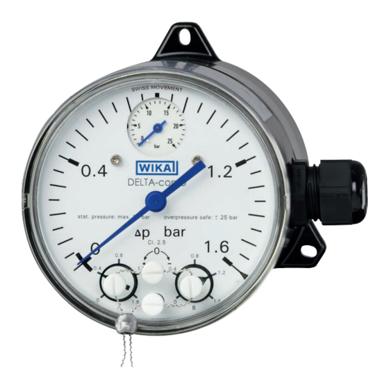
Differential pressure gauge with integrated working pressure indication
and up to two micro switches, model DPGS40TA
Operating instructions
Betriebsanleitung
DELTA-comb
EN
DE
Kapitel
Inhaltsverzeichnis

Verwandte Anleitungen für WIKA DELTA-comb DPGS40TA


Inhaltszusammenfassung für WIKA DELTA-comb DPGS40TA
- Seite 29 Entsorgung ..... . . 54 Anhang 1: Zulassung Germanischer Lloyd Anhang 2: SIL-Zertifikat Anhang 3: VdTÜV-Bescheinigung „Strömung 100“ Konformitätserklärungen finden Sie online unter www.wika.de. WIKA Betriebsanleitung DPGS40TA mit Bauteilprüfung...
-
Seite 30: Allgemeines
… weist auf eine möglicherweise gefährliche Situation hin, die zum Tod oder zu schweren Verletzungen führen kann, wenn sie nicht gemieden wird. Information … hebt nützliche Tipps und Empfehlungen sowie Informationen für einen effizienten und störungsfreien Betrieb hervor. WIKA Betriebsanleitung DPGS40TA mit Bauteilprüfung... -
Seite 31: Sicherheit
Steuerung von Filtern, Kompressoren und Pumpen. Das Gerät ist ausschließlich für den hier beschriebenen bestimmungsgemäßen Verwendungszweck konzipiert und konstruiert und darf nur dementsprechend verwendet werden. Ansprüche jeglicher Art aufgrund von nicht bestimmungsgemäßer Verwendung sind ausgeschlossen. WIKA Betriebsanleitung DPGS40TA mit Bauteilprüfung... -
Seite 32: Zusatzhinweise Für Den Einsatz Als Strömungsbegrenzer Gemäß Vdtüv Merkblatt „Strömung 100:2006
Blockventilen ist darauf zu achten, dass die Wirkdruckleitung zwischen Blockven- til und dem Wirkdruckaufnehmer als Bestandteil des Schaltgliedes mindestens 500 mm lang ist. Die Anforderungen an Wirkdruckleitungen gemäß VdTÜV Merkblatt „Strömung 100:2006“ Abschnitt 5.7.2.3 müssen eingehalten werden. WIKA Betriebsanleitung DPGS40TA mit Bauteilprüfung... -
Seite 33: Funktionale Sicherheit Der Sil-Ausführung
Funktionale Sicherheit sicherheitsbezogener elektrischer/ elektronischer/programmierbarer elektronischer Systeme IEC 61511 Edition 1.0 Funktionale Sicherheit – Sicherheitstechnische Systeme für die Prozessindustrie ISO EN 13849-1:2008 Sicherheit von Maschinen – Sicherheitsbezogene Teile von Steuerungen – Teil 1: Allgemeine Gestaltungsleitsätze WIKA Betriebsanleitung DPGS40TA mit Bauteilprüfung... -
Seite 34: Abkürzungen
Integrity Level (SIL 1 bis SIL 4). Jeder Level entspricht einem Wahrscheinlichkeitsbereich mit welchem ein sicherheitsbezogenes System die festgelegten Sicherheitsfunktionen anforderungsgemäß ausführt. Je höher der Safety Integrity Level der sicherheitsbezo- genen Systeme ist, umso größer die Wahrscheinlichkeit, dass die Sicherheitsfunktion ausgeführt wird. WIKA Betriebsanleitung DPGS40TA mit Bauteilprüfung... - Seite 35 Mittlere Zeit bis zum Auftreten eines gefahrbringenden Ausfalls Anzahl von Zyklen, bis 10 % der Komponenten gefährlich ausgefal- len sind Mittlere Anzahl der jährlichen Betätigungen β-Faktor Faktor für den Ausfall infolge gemeinsamer Ursachen, im Hinblick auf das Zusammenwirken mehrerer Kanäle WIKA Betriebsanleitung DPGS40TA mit Bauteilprüfung...
-
Seite 36: Bestimmungsgemäße Verwendung In Sicherheitsanwendungen
Einsatzfall mit den Anforderungen der Applikation zu verglei- chen. Die spezifischen Kenngrößen sind immer in Hinblick auf die ange- nommene Schalthäufigkeit zu betrachten. 2.3.6 Typenschild und Sicherheitskennzeichnungen S ... mit Option VdTüV „Strömung 100“ S ... mit Option SIL WIKA Betriebsanleitung DPGS40TA mit Bauteilprüfung... -
Seite 37: Einschränkung Der Betriebsarten
Grundgenauigkeit (Messabweichung, Linearitätsfehler) ■ Einfluss der Umgebungstemperatur im Bereich -10 °C ... +70 °C ■ Einfluss von bis zu 259.835 Lastwechseln ■ Die Gesamtsicherheitsgenauigkeit beträgt -12 % … +8 % der Messspanne für den Differenzdruck. WIKA Betriebsanleitung DPGS40TA mit Bauteilprüfung... -
Seite 38: Einsatzgrenzen
PFD -Wert. Üblicherweise wird von einer Wiederholungs- prüfung von 1 Jahr ausgegangen, siehe Zertifikate V 495.01/15 und V 495.02/15. 2.3.13 Test der Sicherheitsfunktion Beim Test der gesamten Sicherheitsfunktion prüfen, ob die Schalter ordnungsge- mäß funktionieren. WIKA Betriebsanleitung DPGS40TA mit Bauteilprüfung... -
Seite 39: Gerätespezifische Sicherheitstechnische Kenngrößen
Austausch des Gerätes muss ein Funktionstest der gesamten Si- cherheitsfunktion (Sicherheitsloop) gestartet werden, um zu prüfen, ob die Sicherheitsfunktion des Systems immer noch gewährleistet ist. Die Funktionstests dienen dazu, die einwandfreie Funktion der Sicherheitseinrichtung SIS im Zusammenwirken aller Komponenten (Sensor, Logikeinheit, Aktor) nachzuweisen. WIKA Betriebsanleitung DPGS40TA mit Bauteilprüfung... -
Seite 40: Personalqualifikation
Vorschriften beachtet werden. WARNUNG! Messstoffreste in ausgebauten Messgeräten können zur Gefährdung von Personen, Umwelt und Einrichtung führen. Ausreichende Vorsichtsmaßnahmen ergreifen. WARNUNG! Die maximale Oberflächentemperatur des Gerätes darf die Zündtemperatur brennbarer Messstoffe nicht überschreiten. Ausreichende Vorsichtsmaßnahmen ergreifen. WIKA Betriebsanleitung DPGS40TA mit Bauteilprüfung... -
Seite 41: Beschilderung, Sicherheitskennzeichnungen
Vor Montage und Inbetriebnahme des Gerätes unbedingt die Betriebsanleitung lesen! Verbrennungsgefahr! Möglicherweise gefährliche Situation durch heiße Oberflächen. Aufgrund der maximal zulässigen Prozesstemperatur von 90 °C können Messzellen, Anschlussstücke, Ventile oder sonstige An- bauteile eine Temperatur von 90 °C erreichen. WIKA Betriebsanleitung DPGS40TA mit Bauteilprüfung... -
Seite 42: Tecnische Daten
Achsabstand 26 mm Messglieder Differenzdruck: Druckfedern aus CrNi-Stahl 1.4310 und Trenn- (messstoffberührt) membrane aus FPM/FKM (Option: NBR) Betriebsdruck: Rohrfeder aus Cu-Legierung Übertragungsteile CrNi-Stahl 1.4301, 1.4305, 1.4310, FPM/FKM (Option: NBR) (messstoffberührt) Dichtungen FPM/FKM (Option: NBR) (messstoffberührt) Zeigerwerk Kupferlegierung WIKA Betriebsanleitung DPGS40TA mit Bauteilprüfung... -
Seite 43: Elektrischer Kontakt
Elektrischer Anschluss Kabelverschraubung M20 x 1,5 mit 1 m freiem Kabel 1) I max. = 1,4 A für Ausführung nach VdTÜV Merkblatt „Strömung 100“ Weitere technische Daten siehe jeweiliges Typenschild, WIKA-Datenblatt und Bestellunterlagen. Für Typen mit optionalem Explosionsschutz „Zusatzinformation für explosionsgefährdete Bereiche (Ex i), Typen DPS40, DPGS40, DPGS40TA und... -
Seite 44: Aufbau Und Funktion
Stützflächen (6) erreicht. Die Schaltpunktverstellung erfolgt über die frontseitig zugänglichen Einstell- schrauben (7). Die Hilfsskalen (8) erleichtern die Schaltpunkteinstellung. ⊖ ⊕ 4.2 Lieferumfang Lieferumfang mit dem Lieferschein abgleichen. WIKA Betriebsanleitung DPGS40TA mit Bauteilprüfung... -
Seite 45: Transport, Verpackung Und Lagerung
Explosionsgefährdete Umgebung, entzündliche Atmosphären ■ WARNUNG! Vor der Einlagerung des Gerätes müssen alle ggf. anhaftenden Messstoffreste entfernt werden. Dies ist besonders wichtig, wenn das Medium gesundheitsgefährdend ist, wie z. B. ätzend, giftig, krebserregend, radioaktiv, usw. WIKA Betriebsanleitung DPGS40TA mit Bauteilprüfung... -
Seite 46: Inbetriebnahme, Betrieb
Zur Abdichtung der Anschlüsse sind Flachdichtungen, Dichtlinsen oder ■ WIKA-Profildichtungen einzusetzen. Um das Gerät in die Stellung zu bringen, in der sich die örtliche Anzeige am besten ablesen lässt, ist ein Anschluss mit Spannmuffe oder Überwurfmutter zu empfehlen. Beim Ein- und Ausschrauben dürfen die Geräte nicht am Gehäuse angezogen werden, sondern nur an den... -
Seite 47: Temperaturbelastung
Geräten selbst abhängig, sondern hauptsächlich von der jeweiligen Messstofftemperatur! Bei gasförmigen Stoffen kann sich die Temperatur durch Kompressionswärme erhöhen. In solchen Fällen muss ggf. die Druckänderungsgeschwindigkeit gedrosselt bzw. die zulässige Messstofftemperatur reduziert wer- den. WIKA Betriebsanleitung DPGS40TA mit Bauteilprüfung... - Seite 48 Beispiele Kondensat siedende „Flüssig- trockene feuchte Luft Wasserdampf Flüssig- gase“ Luft Rauchgase keiten Manometer oberhalb des Entnahme- stutzens Manometer unterhalb des Entnah- mestutzens Abmessungen in mm Kabelverschraubung M20 x 1,5 mit 1 m Kabel WIKA Betriebsanleitung DPGS40TA mit Bauteilprüfung...
-
Seite 49: Elektrischer Anschluss
Die vorgesehenen Netzanschlussleitungen müssen für die größte Stromauf- ■ nahme des Gerätes bemessen sein und IEC 227 oder IEC 245 entsprechen. Die Geräte sind in den Potenzialausgleich der Anlage mit einzubeziehen. ■ Leistungsdaten siehe Kapitel 3 „Technische Daten“ WIKA Betriebsanleitung DPGS40TA mit Bauteilprüfung... -
Seite 50: Sicherheitshinweise Bei Installation
2. Kontakt 1. Kontakt Kabelanschlussdose Für den Sicherheitsstromkreis, der bei Unterschreiten des Min- destdurchflusses die Beheizung des Dampferzeugers abschalten soll, darf nur der Schließer des Umschaltkontaktes angeschlossen werden (d.h. der bei Δp = 0 offene Kreis)! WIKA Betriebsanleitung DPGS40TA mit Bauteilprüfung... - Seite 51 Anschlussleitungen müssen für den Umgebungstemperaturbereich der ■ Applikation geeignet sein. Kabeleinführung mit den entsprechend zugelassenen Kabelverschraubungen ■ dicht verschließen. Kabelverschraubung Kabelanschlussdose bzw. Winkelsteckverbinder Nur Kabel mit Durchmesser 7 ... 13 mm verwenden Anschlusskabel fest verlegen. ■ WIKA Betriebsanleitung DPGS40TA mit Bauteilprüfung...
-
Seite 52: Inbetriebnahme
Prozess sowie Vermeidung einseitiger Überdruckbelastung während der Anfahr- bzw. Betriebsphase (bei geöffnetem Druckausgleichsventil). Entlüftung der Messleitungen bei flüssigen ■ Messstoffen und Spülung der Messlei- Absperrventil Entlüftungs- ⊖ ventil -Seite tungen, um Verunreinigungen zu entfernen. WIKA Betriebsanleitung DPGS40TA mit Bauteilprüfung... -
Seite 53: Befestigungsrand Für Schalttafelmontage
■ 1. Druckausgleichsventil öffnen 2. Absperrventil der ⊕- und ⊖-Messstoffkammer schließen Arbeitsgangfolge zur Demontage des Messgerätes bei laufenden Prozess ■ 1. Absperrventil der ⊕- und ⊖-Messstoffkammer schließen 2. Entlüftungsventil öffnen 7.2 Befestigungsrand für Schalttafelmontage Schalttafel WIKA Betriebsanleitung DPGS40TA mit Bauteilprüfung... -
Seite 54: Wartung
Ausgebautes Messgerät vor der Rücksendung spülen bzw. säubern, um Mitarbeiter und Umwelt vor Gefährdung durch anhaftende Messstoffreste zu schützen. 9.3 Entsorgung Durch falsche Entsorgung können Gefahren für die Umwelt entstehen. Gerätekomponenten und Verpackungsmaterialien entsprechend den landesspezifischen Abfallbehandlungs- und Entsorgungsvorschriften umweltgerecht entsorgen. WIKA Betriebsanleitung DPGS40TA mit Bauteilprüfung... - Seite 64 WIKA subsidiaries worldwide can be found online at www.wika.com. WIKA-Niederlassungen weltweit finden Sie online unter www.wika.de. WIKA Alexander Wiegand SE & Co. KG Alexander-Wiegand-Straße 30 63911 Klingenberg • Germany Tel. +49 9372 132-0 Fax +49 9372 132-406 info@wika.de www.wika.de WIKA operating instructions DPGS40TA with component testing...