Centrometal El-Cm Compact 6 Technische Anleitung
Inhaltsverzeichnis
Verfügbare Sprachen
Verfügbare Sprachen
HEATING TECHNIQUE
Centrometal d.o.o. - Glavna 12, 40306 Macinec, Croatia, tel: 040 372 600, fax: 040 372 611
TEHNIČKO UPUTSTVO / TECHICAL MANUAL /
TECHNISCHE ANLEITUNG / ISTRUZIONI TECNICHE
za montažu, upotrebu i održavanje toplovodnog elektrokotla te za montažu dodatne opreme /
for assembling, use and maintenance of the electric boiler and additional equipment /
für Montage, Anwendung und Instandhaltung des Elektroheizkessels und Montage der zusätzlichen Ausrüstung /
per il montaggio,uso e manutenzione della caldaia elettrica e per il montaggio degli accessori
HR
EN
DE
IT
El-Cm Compact
TUELCMC-08/2017
Inhaltsverzeichnis

Verwandte Anleitungen für Centrometal El-Cm Compact 6


Inhaltszusammenfassung für Centrometal El-Cm Compact 6
- Seite 1 HEATING TECHNIQUE Centrometal d.o.o. - Glavna 12, 40306 Macinec, Croatia, tel: 040 372 600, fax: 040 372 611 TEHNIČKO UPUTSTVO / TECHICAL MANUAL / TECHNISCHE ANLEITUNG / ISTRUZIONI TECNICHE za montažu, upotrebu i održavanje toplovodnog elektrokotla te za montažu dodatne opreme / for assembling, use and maintenance of the electric boiler and additional equipment / für Montage, Anwendung und Instandhaltung des Elektroheizkessels und Montage der zusätzlichen Ausrüstung /...
-
Seite 31: Technische Angaben
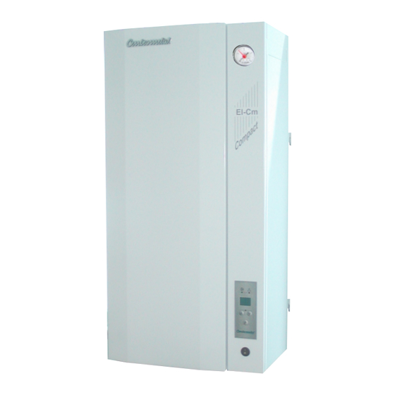
Technische Angaben Abb. 1. Allgemeine Maße des Elektroheizkessels El-Cm Compact Manometer El-Cm Vorderer Deckel (abnehmbar, 4 Schrauben abschrauben) Regelungskonsole (kann geöffnet werden, 2 Schrauben abschrauben) Digitale modale Kesselregelung TEHNIKA GRIJANJA Hauptschalter TECHNISCHE ANGABEN El-Cm Compact (kW) Wärmeleistung (lit.) Kesselwasservolumen (kg) Kesselmasse (bar) Max. - Seite 32 Hauptteile Abb. 2. - Teile des Elektroheizkessels El-Cm Compact Vorlauf Rücklauf (Raumthermostat) Elektrische Speisung) Regelungskasten Mikroschalter Sonde für Fühler 1 2 3 Druckschalter Heizkessel Sicherheitsthermostat Elektrischer Wärmer Ausdehnungsgefäß Zirkulationspumpe Aufhängung Wärmeisolierung Heizkesselkörper Heizkesselverschalung Befüllen / Entleeren Sicherheitsventil Elektrische Wärmer Technische Anweisungen El-Cm Compact...
-
Seite 33: Beschreibung Des Kessels
Ihnen, diesen Anweisungen sorgfältig zu folgen, damit Ihr Heizkessel El-Cm Compact länger und besser betrieben werden kann. Das Unternehmen Centrometal d.o.o. übernimmt keine Haftung für eventuelle Fehler in diesen Anweisungen, die aus den Druck oder Schreibfehler hervorgehen unter Vorbehalt des Rechtes auf Eintragen ohne Vorankündigung von derjenigen Änderungen bei den Produkte, die als notwendig und nützlich betrachtet... - Seite 34 Hauptteile RÜCKLAUF Das Rohr des Rücklaufs (1“) ist mit dem blauen Aufkleber gekennzeichnet und befindet sich auf der oberen linken Seite des Kessels. Der Rücklauf ist so durch den Kessel geführt, so dass dieser den Kessel und die Elektrowärmer gleichmäßig umspült. SONDE FÜR DEN FÜHLER Die Sonde für den Fühler der Heizkesselregelung befindet sich auf der oberen Seite des Heizkesselkörpers.
-
Seite 35: Montage Des Kessels
Montage des Kessels 4.0. MONTAGE DES KESSELS Der Elektroheizkessel El-Cm Compact ist für die Montage auf die Wand vorgesehen, für welche sich auf der hinteren Seite des Kessels die Konsolen zum Aufhängen befinden. Es können Wandeinlagen aus Metall (Dübel) mit der Schraube M10 oder stärkere Wandeinlagen aus Kunststoff verwendet werden. -
Seite 36: Anschließen Auf Heizungsinstallation
Anschließen auf Heizungsinstallation 5.0. ANSCHLIESSEN DES HEIZKESSELS El-Cm Compact AN DIE HEIZUNGSINSTALLATION Anschließen an die Rohrinstallation des Heizsystems und die Inbetriebnahme des Heizkessels muss in Übereinstimmung mit den gültigen technischen Normen, seitens einer Fachperson durchgeführt werden, welche die Verantwortung übernehmen muss. Die richtige Leistung des Heizkessels wird entsprechend dem Raum der beheizt werden soll, dessen Zweck und der Wärmeverluste ausgewählt. -
Seite 37: Elektroanschluss, Regelung
Elektroanschluss, Regelung 6.0. E LEKTROANSCHLUSS Technischen Vorschriften seitens einer befugten Fachperson durchgeführt werden. Die komplette Elektroinstallation des Kessels wird in der Fabrik fertiggestellt. Alle anderen Anschlüsse (Heizkesselspeisung, Raumthermostat) müssen auf die vorgesehenen Reihenklemme angebracht werden, welche sich auf der oberen linken Seite des Kessels befindet. -
Seite 38: Elektrisches Schema
Elektrisches Schema Schema 1 - Elektrisches Schema des Heizkessels El-Cm Compact 6-12 kW (3-poliger Anschluss) REGELUNGSPLATTE Pumpe Leistenklemme EG EG EG EG EG EG LEGENDE: P - Hauptschalter K - Schaltschütz 1 LED-DISPLAY ST - Sicherheitsthermostat EG - Elektrowärmer K - Schaltschütz... -
Seite 39: Schema 2 - Elektrisches Schema Des Heizkessels El-Cm Compact 15-18 Kw (3-Poliger Anschluss)
Elektrisches Schema Schema 2 - Elektrisches Schema des Heizkessels El-Cm Compact 15-18 kW (3-poliger Anschluss) REGELUNGSPLATTE Pumpe Leistenklemme EG EG EG EG EG EG EG EG EG LEGENDE: P - Hauptschalter K - Schaltschütz 1 LED-DISPLAY ST - Sicherheitsthermostat EG - Elektrowärmer K - Schaltschütz RE - Regelelektronik Technical manual El-Cm Compact... -
Seite 40: Schema 3 - Elektrisches Schema Des Heizkessels El-Cm Compact 21-27 Kw (3-Poliger Anschluss)
Elektrisches Schema Schema 3 - Elektrisches Schema des Heizkessels El-Cm Compact 21-27 kW (3-poliger Anschluss) REGELUNGSPLATTE Pumpe Leistenklemme EG EG EG EG EG EG EG EG EG EG EG LEGENDE: P - Hauptschalter K - Schaltschütz 1 LED-DISPLAY ST - Sicherheitsthermostat EG - Elektrowärmer K - Schaltschütz RE - Regelelektronik... - Seite 41 Ersetzen des Elektrowärmers 7.0. TECHNISCHE ANGABEN ÜBER DIE REGELUNG - Anschlussspannung:.................400V / 50Hz - Regelung des Betriebs:..............Modulregelung - Verbrauch der elektronischen Teile:............max 10 VA - Regelungsbereich:...................20-85°C 8.0. ERSETZEN DES ELEKTROWÄRMERS Bevor der vordere Deckel demontiert wird, muss die Stromzufuhr des Heizkessels unterbrochen werden. Danach muss der vordere Deckel und die untere Verschalungsplatte (befestigt durch Schrauben) demontiert werden.
- Seite 42 Regelung 9.0. REGELUNG Abb 5. - Digitale Regelung Fehler (LED- Leuchte) Pumpe (LED- Leuchte) Display Betrieb des Elektrowärmers (LED- Leuchte) Funktionstasten Die Heizkesselregelung funktioniert so, dass die gemessene Temperatur mit der vorgegebenen (gewünschten) Temperatur verglichen wird und dementsprechend die optimale Zuordnung der Leistung für das Aufheizen des Systems auf ausgesucht wird.
- Seite 43 Tabelle der Widerstände von Kesselfühler TABELLE DER WIDERSTÄNDE VON NTC 5k/25°C KESSELFÜHLER (Messbereich - 20 bis + 130 °C) Temperatur (°C) Widerstand (Ω) 48.535 36.465 27.665 21.158 16.325 12.694 9.950 7.854 6.245 5.000 4.028 3.266 2.663 2.184 1.801 1.493 1.244 1.041 740,7 629,0...
- Seite 44 Fehler Beispiel: Heizkessel El-Cm Compact 12 kW Nach dem Einschalten wird der Heizkessel mit der höchsten Leistung aufgewärmt, bis die gewünschte Temperatur erreicht wird. Nach dem Erreichen der gewünschten Temperatur reguliert die Reguliert sich der Kessel mit der erfofderlichen Leistung z.B. in Schritten 12kW, 6kW, 4kW, 2kW (MOD1). Wird durch die Zuordnung dieser Leistungen die gewünschte Temperatur nicht erreicht, erkennt die Regelung das und die Leistung wird erhöht und es erfolgt Leistungszuordnung nach System 12kW, 6kW, 4kW (MOD 2).
- Seite 60 Centrometal d.o.o. shall not be responsible for possible incorrect data caused by printing errors or error made in transcription and all figures and diagrams are for explanatory purposes only and relevant adjustment have to be made at the spot.