Herunterladen Inhalt Inhalt Diese Seite drucken
Inhaltsverzeichnis

Werbung

Verfügbare Sprachen

Verfügbare Sprachen

Installationsanleitung
DE
Wärmerückgewinnungssysteme
Installation instructions
UK
Heat recovery systems
Notice d'installation
FR
Systèmes de récupération de chaleur
w w w . a e r e x . d e
Reco-Boxx
RB 170 L
RB 170 R
RB 170 CL
RB 170 CR

Werbung

Inhaltsverzeichnis
loading

Inhaltszusammenfassung für aerex RB 170 L

  • Seite 1 Installationsanleitung Wärmerückgewinnungssysteme Installation instructions Heat recovery systems Notice d'installation Systèmes de récupération de chaleur Reco-Boxx RB 170 L RB 170 R RB 170 CL RB 170 CR w w w . a e r e x . d e ...
  • Seite 2: Inhaltsverzeichnis

    5. Installationsvorbereitungen ....10 5.1 Transport ......... 10 5.2 Anforderungen Aufstellungsort ..10 6. Installation ..........11 6.1 Vorgehensweise ......11 Impressum: © AEREX HaustechnikSysteme GmbH. 6.2 Installation Lüftungsgerät ....11 Deutsche Originalanleitung. Druckfehler, Irrtümer und 6.3 Schallschutz ........12 technische Änderungen vorbehalten Die in diesem Dokument erwähnten Marken, Handelsmarken und...
  • Seite 3: Allgemeine Hinweise

     L = Linksausführung anleitung des RB 170 aufmerksam durch. Folgen Sie den Anweisungen. RB 170 R, RB 170 L: Standardgerät mit Übergeben Sie die Anleitungen an Raumluftsteuerung RB-ZF4 und 2x G4-Filter. den Besitzer zur Aufbewahrung für RB 170 CR, RB 170 CL: Komfortgerät mit einen späteren Gebrauch.
  • Seite 4: Steuerungen, Sensoren

    de │ 2. Produktinformationen Pos. Bezeichnung Funktion Kondensat- Zum Anschluss des bogen mit Ablaufschlauchs. Kabelver- Für Netzleitung, Reduzierstück Im Wärmetauscher schraubung im Gerät fertig angefallenes Kon- verdrahtet. densat wird hierüber Hauptschalter Netzschalter abgeleitet. Ein-/Aus Frostschutz- Misst die Temperatur Türkontakt- Sicherheitseinrich- Temperatur- der Fortluft direkt nach schalter...
  • Seite 5: Bestimmungsgemäße Verwendung

    Betrieb des Systems zu gewährleisten. Raumluftsteuerung ein. ● Wenn Sie die Frontab- 2.5 Vorhersehbare Fehlanwendungen deckung öffnen, schaltet ein AEREX haftet nicht für Schäden durch Sicherheitsabschalter (Tür- bestim-mungswidrigen Gebrauch. Gerät auf keinen Fall einsetzen: kontaktschalter) die Ventila- ● während der Bauphase.
  • Seite 6: Installation, Anschluss

    de │ 3. Sicherheitshinweise ● Veränderungen und Umbau- 3.3 Reinigung, Wartung ten am Lüftungsgerät sind Schalten Sie das Lüftungsgerät nicht zulässig und entbinden vor Reinigungs- und Wartungs- den Hersteller von jeglicher arbeiten mit dem Hauptschalter Gewährleistung und Haftung. [6] aus. Für weitere Informationen zur 3.2 Installation, Anschluss Reinigung und Wartung ...
  • Seite 7 3. Sicherheitshinweise│ de 2. die Abgasabführung der Bei Abgasanlagen von Feuer- raumluftabhängigen Feuer- stätten für feste Brennstoffe darf stätte durch besondere die Absperrvorrichtung nur von Sicherheitseinrichtungen Hand bedient werden können. überwacht wird. Bei raum- Die Stellung der Absperrvor- luftabhängigen Feuerstätten richtung muss an der Einstel- für flüssige oder gasförmige lung des Bedienungsgriffes...
  • Seite 8: Systemkomponenten

    Wärmetauscher geleitet. ● mit1x CO -Sensor oder 1x VOC-Sensor oder 1x Feuchtesteuerung RFS. ● Das Lüftungsgerät besitzt vier Rohran- schlüsse DN 125. Für passende, aufsteck- RB-D1-ZF4 nicht mit RB-ZF4 bare Steckverbinder mit Lippendichtung oder kombinierbar. Rohrbogen  AEREX-Katalog oder Internet.
  • Seite 9: -Sensor (Skd) / Voc--Sensor (Luftqualitätssensor Eaq 10/2)

    4. Systemkomponenten │ de 4.3 CO -Sensor (SKD) / VOC-Sensor 4.4 Feuchtesteuerung RFS (Luftqualitätssensor EAQ 10/2) Siehe auch Anschlussvariante 4 in Kap. 6.11. Siehe auch Anschlussvariante 4 in Kap. 6.11. Gerätebeschädigung. ACHTUNG Sensor zur Erfassung von Kohlendioxid. RFS nie gemeinsam mit einem Der CO -Gehalt der Luft gilt als Indikator für - oder VOC-Sensor betreiben.
  • Seite 10: Zuluft-Temperaturfühler Ntc 15

    de │ 4. Systemkomponenten 4.7 Zuluft-Temperaturfühler NTC 15 4.12 Bypass Siehe auch Anschlussvariante 6 in Kap. 6.13. In RB 170-Bypassgeräten befindet sich serienmäßig in der Frontabdeckung [1] ein Mit einem NTC werden hydraulische Nach- Bypasskanal. heizregister vor Vereisung geschützt. Bei Unterschreitung der Frostschutztemperatur Ist die Außenluft kühler als die Raumluft von 5 °C schaltet das Lüftungsgerät aus.
  • Seite 11: Installation

    6. Installation │ de ● Bringen Sie Revisionsöffnungen in Ihrem 6. Installation Rohrleitungssystem an. ● Verwenden Sie unbedingt geeignetes 6.1 Vorgehensweise Schalldämmungs-, Dämm- und Installa- 1. Bringen Sie die Wandhalterung an, tionsmaterial, wie z. B. passende Rohr-  Kapitel 6.2.2. schalldämpfer, SLFM 50-125-1000, Zuluft- und Abluftventile, Überströmöffnungen etc.
  • Seite 12: Montage Der Wandhalterung

    de │ 6. Installation 6.2.2 Montage der Wandhalterung 6.3 Schallschutz Verwenden Sie für die Wandmontage die mit- Die Schallemissionen durch die Lüftungs- gelieferte, spezielle Wandhalterung. anlage sind von vielen Faktoren abhängig, zum Beispiel Gebäudebauweise, Lüftungs- Verletzungsgefahr bei komponenten usw. Montage an zu schwach Führen Sie die Lüftungsanlage deshalb dimensionierter Wand.
  • Seite 13: Ausführung Der Luftkanäle

    6. Installation │ de 3. Schließen Sie am Kondensatbogen ein 6.3.2 Ausführung der Luftkanäle Ablaufrohr [R] (Ø 28) oder einen ¾“-Wasserschlauch [S] fachgerecht an. Ohne Schalldämpfer Schall- ACHTUNG Verwenden Sie zum Anschluss des emmissionswerte zu hoch. Wasserschlauchs das mitgelieferte Redu- Vorgeschriebene Schalldruck- zierstück [16.2] (d=28mm auf d=19mm).
  • Seite 14: Lüftungskanäle

    de │ 6. Installation 6.5 Lüftungskanäle Keimbefall ist möglich, falls ACHTUNG Sie keinen Siphon mit Tropf- trichter verwenden. Es besteht Gerätebeschädigung durch ACHTUNG dann keine Entkoppelung Gegenstände in den vom Kanalsystem. Lüftungskanälen. Der Siphon benötigt eine Installieren Sie zuerst das Lüf- Sperrwasserhöhe [H] von tungsgerät mit allen Zu- und min.
  • Seite 15: Dämmung Der Lüftungskanäle

    6. Installation │ de 6.5.2 Dämmung der Lüftungskanäle 1. Dämmen Sie die Kanäle bis zum Lüftungs- gerät von außen diffusionsdicht, um Kon- densatbildung an der Außenseite des Fort- luft- und Außenluftkanals zu verhindern. 2. Die Dämmung der Rohrleitungen muss nach den bestehenden Regeln der Tech- nik ausgeführt werden.
  • Seite 16: Anschlüsse Und Abmessungen

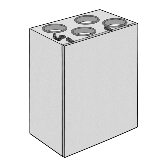
    │ 6. Installation 6.6 Anschlüsse und Abmessungen A = RB 170 L/R Standardgerät Rohranschluss Außenluft B = RB 170 CL/CR Komfortgerät Rohranschluss Zuluft C = RB 170 CBL/CBR Bypassgerät III Rohranschluss Abluft IV Rohranschluss Fortluft Elektroanschluss VI Kondensatablauf ● Abbildung RB 170 in Rechtsausführung „R“...
  • Seite 17: Elektrischer Anschluss

    6. Installation ‒ Elektrischer Anschluss │ de 6.7 Elektrischer Anschluss 6.7.2 Kabelverschraubung, Kabeldurchführung ● Der elektrische Anschluss darf nur von Die Netzleitung ist bereits fertig verdrahtet. Elektrofachkräften gemäß nachfolgenden Schaltbildern und Verdrahtungsplan im Anhang vorgenommen werden. ● Bei der Elektroinstallation sind die geltenden Vorschriften zu beachten, in Deutschland insbesondere VDE 0100 mit den entsprechenden Teilen.
  • Seite 18: Steuerplatine

    de │ 6. Installation ‒ Elektrischer Anschluss 5. Schließen Sie die Leitungen gemäß den Verdrahtungsplänen in Kapitel 12 an. Für Anschlussvarianten  Kap. 6.8…6.13. 6. Schieben Sie den Elektronikeinschub in das Elektronikfach ein. Befestigen Sie den Elektronikeinschub mit den beiden Schrauben.
  • Seite 19: Jumpereinstellungen

    6. Installation ‒ Elektrischer Anschluss │ de 6.7.4 Jumpereinstellungen Werkseinstellung: Jumper 10 Jumper 10 offen. Alternativ Jumper 10 gebrückt: - / VOC- oder RFS- Sensor freigeschaltet. Ohne Sensor muss Jumper 10 offen sein. 6.7.5 Frostschutztemperaturen Werkseinstellung RB 170: Eine interne Frostschutzüberwachung ver- Jumper auf Steuerplatine hindert das Einfrieren des Wärmetauschers bei tiefen Außentemperaturen.
  • Seite 20: Anschlussvariante 1: Rb-Zf4

    de │ 6. Installation ‒ Anschlussvarianten Anschluss an: 6.8 Anschlussvariante 1: RB 170 ● Standardgerät mit RB-ZF4 ● Komfortgerät siehe auch Verdrahtungsplan im Anhang ● Option: Zusätzlich zu RB-D1-ZF4 Sie können bis zu 5 Raumluftsteue- RB 170-Elektronikeinschub rungen RB-ZF4 am Lüftungsgerät Steuerplatine: Jumper 8 gebrückt anschließen.
  • Seite 21: Anschlussvariante 2: Rb 170 Mit Rb-D1-Zf4

    6. Installation ‒ Anschlussvarianten │ de 6.9 Anschlussvariante 2: RB 170 mit RB-D1-ZF4 siehe Anhang, Verdrahtungsplan des jeweiligen RB 170-Gerätes Anschluss an: Für die Verdrahtung der Steuer- ● Bypassgerät leitung W2 siehe Verdrahtungspläne ● Option: Standard- oder Komfortgerät in Kapitel 12. RB 170-Elektronikeinschub Steuerplatine: Jumper 8 gebrückt (= Werkseinstellung)
  • Seite 22: Betriebsanzeige

    de │ 6. Installation ‒ Anschlussvarianten Das Lüftungsgerät ist werkseitig für 6.10 Anschlussvariante 3: RB 170 den Anschluss der Raumluftsteue- mit RB-ZF4 oder RB-D1-ZF4 rung RB-ZF4 vorbereitet. Jumper 8 und externer Betriebsanzeige auf der Steuerplatine A2 ist gesetzt. siehe auch Verdrahtungsplan im Anhang RB-D1-ZF4 nicht mit RB-ZF4 kombinierbar.
  • Seite 23: Voc- Oder Rfs-Sensor

    6. Installation ‒ Anschlussvarianten │ de Anschluss eines CO -, Luftqualitäts- oder Feuch- 6.11 Anschlussvariante 4: RB 170 tesensors zur bedarfsgerechten Frischluftzufuhr. mit RB-ZF4 oder RB-D1-ZF4 und Das Lüftungsgerät reagiert nur dann auf den -, VOC- oder RFS-Sensor Sensor, wenn an der Raumluftsteuerung siehe auch Verdrahtungsplan im Anhang Lüftungsstufe 2 (Nennlüftung) angewählt ist.
  • Seite 24: Gleichzeitiger Betrieb Von Feuerstätte Und Lüftungsgerät

    de │ 6. Installation ‒ Anschlussvarianten 6.12 Anschlussvariante 5: RB 170 mit RB-ZF4 oder RB-D1-ZF4 und Differenzdruckwächter Verdrahtungsplan im Anhang  Gleichzeitiger Betrieb von Feuerstätte und Lüftungsgerät Der Differenzdruckwächter P ist eine Sicherheitseinrichtung, die einen gleichzeitigen Betrieb einer Lüftungsanlage in Verbindung mit einer raumluft- abhängigen Feuerstätte ermöglicht.
  • Seite 25: Temperaturfühler (Ntc 15)

    6. Installation ‒ Anschlussvarianten │ de Für RB 170 mit hydraulischem Nach- 6.13 Anschlussvariante 6: RB 170 heizregister oder bei Einsatz in Passiv- mit RB-ZF4 oder RB-D1-ZF4 und häusern muss zusätzlich ein NTC 15 Zuluft-Temperaturfühler (NTC 15) zum Schutz vor Vereisung (bei zu siehe auch Verdrahtungsplan im Anhang kalter Zuluft) installiert werden.
  • Seite 26: Inbetriebnahme

    de │ 7. Inbetriebnahme Für Einstellwerte und Einstellmöglich- 7. Inbetriebnahme keiten  Kapitel 7.3 und 7.4: ● Zuluft: Lüftungsstufe 1, 2 und 3 mit den blauen Potentiometer-Stellrädern S1, S2 7.1 Vor der Inbetriebnahme und S3. 1. Kontrollieren Sie vor der Inbetriebnahme ●...
  • Seite 27: Lüftungsstufen-Werkseinstellung

    7. Inbetriebnahm │ de 7.3 Lüftungsstufen-Werkseinstellung 7.3.2 Spannungs-/Volumenstromtabelle Volumenstrom Steuerspannung Zuluft (blaue Potentiometer-Stellräder) [m³/h] Abluft (rote Potentiometer-Stellräder) 7.4 Volumenstromeinstellung 7.3.1 Erweiterter Einstellbereich für jede mit Voltmeter Lüftungsstufe Alternativ lassen sich die Volumenströme der Die Volumenstromeinstellungen für jede einzelnen Lüftungsstufen auch mit einem Lüftungsstufe sind bei Werkseinstellung Spannungsmessgerät einregulieren.
  • Seite 28: Einstellung Zuluft-Volumenstrom

    AKW-R-160 in Verbindung mit ISO-Form DN 125 0044.0199 7.4.2 Einstellung Abluft-Volumenstrom Kombi-Wandstutzen, Linksaus- führung, passend für RB 170 L, 1. Schließen Sie das Voltmeter (Messbereich RB 170 CL und RB 170 CBL: 1...10 V) an Steckerpin 5 und AKW-L-125 0044.0222 Steckerpin 3 (GND) an.
  • Seite 29: Störungen, Meldungen

    8. Zubehör │ de RB 170- Komfort - und Bypass- 9.1 Raumluftsteuerung RB-ZF4 geräte sind mit einer elektrischen Raumluftsteuerung RB-ZF4 zeigt eine Außenluftvorerwärmung Störung an, wenn alle 3 LEDs blinken. Die ausgestattet. Ursache hierfür ist entweder ein „Ventilator- In RB 170- Komfort - und Bypass- ausfall“, eine „Temperaturfühler-Störung“...
  • Seite 30: Vorgehensweise Bei Ventilatorausfall

    de │ 9. Störungen, Meldungen 9.3.1 Vorgehensweise bei Ventilatorausfall Lebensgefahr durch Strom- schlag. Berühren Sie niemals span- GEFAHR nungsführende Teile. 1. Prüfen Sie die Funktion des Türkontakt- schalters [7]. Tauschen Sie diesen ggf. aus. Bei geschlossener Fronttür (Türkon- taktschalter [7] betätigt) liegt ständig eine Versorgungsspannung von 230 V AC an den Klemmenpaaren „X“...
  • Seite 31: Technische Daten

    11. Entsorgung │ de Lüftungsstufen 10. Technische Daten (Werkseinstellung): Lüftung zum Feuchte- ca. 57 % der Gehäuseabmessung schutz (Intervallbetrieb) reduz. Lüftung (B x H x T) in mm ● Reduzierte Lüftung 60 m³/h 595 x 820 x 375 ● RB 170 Standardgerät ●...
  • Seite 32: Verdrahtungsplan Rb 170-Standardgerät

    de │ 12. Anhang ‒ Verdrahtungsplan RB 170-Standardgerät 12.1 Verdrahtungsplan RB 170-Standardgerät...
  • Seite 33 12. Anhang ‒ Verdrahtungsplan RB 170-Standardgerät │ de RB 170 Standardgerät Jumpereinstellungen (Kapitel 6.7.4) Lüftungsgerät RB 170 J 1-3 Gerätetyp, 000 = RB 170 J 4-5 Frostschutztemperatur (Kap. 6.7.5) Elektronikeinschub Keine Funktion Steuerplatine Jumper 7 offen: Raumluftsteuerung RB-D1-ZF4 Lüftungsstufe 3 wird nach Raumluftsteuerung RB-ZF4 einer Stunde zurückgesetzt.
  • Seite 34: Verdrahtungsplan Rb 170-Komfortgerät

    de │ 12. Anhang ‒ Verdrahtungsplan RB 170-Komfortgerät 12.2 Verdrahtungsplan RB 170-Komfortgerät...
  • Seite 35 12. Anhang ‒ Verdrahtungsplan RB 170-Komfortgerät │ de RB 170 Komfortgerät Jumpereinstellungen (Kapitel 6.7.4) Lüftungsgerät RB 170 J 1-3 Gerätetyp, 000 = RB 170 J 4-5 Frostschutztemperatur (Kap. 6.7.5) Elektronikeinschub Keine Funktion Steuerplatine Jumper 7 offen: Frostschutz-Heizregister Lüftungsstufe 3 wird nach Raumluftsteuerung RB-D1-ZF4 einer Stunde zurückgesetzt.
  • Seite 36: Knx-Bus-Konzept

    de │ 12. Anhang ‒ KNX-Bus-Konzept 12.3 KNX-Bus-Konzept...
  • Seite 37 Annexe: Product fiches RVU´s....109 5.1 Transport ........45 5.2 Requirements at the installation site ... 45 Acknowledgements: © AEREX HaustechnikSysteme GmbH English 6. Installation ..........45 translation from the original German Operating Instructions. We cannot be held responsible for 6.1 Procedure ........45 mistakes or printing errors and retain the right to make 6.2 Installation of ventilation unit ...
  • Seite 38: General Notes

    L = left-hand version maintenance instructions for the RB 170. Follow the instructions. RB 170 R, RB 170 L: Standard unit with Pass the instructions over to the RB-ZF4 room air control and 2x G4 filter. owner for safekeeping for future RB 170 CR, RB 170 CL: Comfort unit with use.
  • Seite 39: Controls, Sensors

    2. Product information │ uk Item Designation Function Frost protection Measures the temperature temperature of the Main switch Mains switch On/Off sensor outgoing air directly Door contact Safety device: Fans downstream of the switch single and/or frost heat exchanger. for standard protection heating Heat exchanger The heat transfer unit, double for...
  • Seite 40: Intended Use

    ● When you open the front 2.5 Foreseeable cases of misuse cover, a safety circuit breaker AEREX is not liable for damages caused by use contrary to the intended purpose. Under (door contact switch) switches no circumstances should the unit be the fans off.
  • Seite 41: Installation, Connection

    3. Safety instructions │ uk 3.2 Installation, connection 3.4 Regulations for operation with fireplaces Only operate the ventilation unit: ● with air filters fitted. Only use 3.4.1 Ventilation requirements original air filters. of fireplaces ● with the voltage and frequen- RB 170 ventilation units may cy stated on the rating plate.
  • Seite 42: Fire Protection Requirements

    uk │ 3. Safety instructions RB 170 ventilation units must 4. System components not be installed if there are air- ventilated fireplaces in the living 4.1 Ventilation unit unit that are connected to exhaust ● Degree of heat provision up to 94 %. gas systems, which themselves ●...
  • Seite 43: Room Air Controls

    (EAQ 10/2 air quality sensor) connectors with lip seal or pipe elbow Also refer to connection option 4 in Chap. 6.11.  AEREX catalogue or internet. sensor for registering carbon dioxide. ● ¾“ condensate discharge outlet, sleeve with The CO content of the air is an indicator of 28 mm diameter lip seal.
  • Seite 44: Rfs Room Air Control

    uk │ 4. System components 4.4 RFS room air control 4.7 NTC 15 supply air temperature sensor Also refer to connection option 4 in Chapter 6.11. Also refer to connection option 6 in Chapter 6.13. Damage to the unit. NOTICE An NTC protects hydraulic re-heating Never operate an RFS together registers from icing over.
  • Seite 45: Bypass

    4. System components │ uk 4.12 Bypass 6. Installation RB 170 bypass units feature a bypass channel in the front cover [1] as standard. 6.1 Procedure If the outside air is cooler than the room air 1. Fit wall bracket,  Chapter 6.2.2. (warm time of the year), the outside air can 2.
  • Seite 46: Mounting The Wall Bracket

    uk │ 6. Installation ● Make a service opening in your duct 6.2.2 Mounting the wall bracket system. Use the special wall bracket provided for wall ● Make sure you use appropriate insulation, mounting. sound-absorbing and installation material such as suitable tubular sound absorbers, Danger of injury if installed SLFM 50-125-1000, supply air and on a wall that is too weak.
  • Seite 47: Sound Insulation

    6. Installation │ uk Recommendation: Install telephony sound 6.3 Sound insulation absorbers to reduce the sound transfer Sound emissions from the ventilation system between the individual rooms. are dependent on many factors, e.g. the construction of the building, ventilation 6.4 Condensate drain components, etc.
  • Seite 48: Ventilation Channels

    uk │ 6. Installation 4. Secure the condensate elbow to prevent it 6.5 Ventilation channels falling out. To do this, attach a cable tie [K] to the condensate elbow and hook the Damage to the unit caused NOTICE cable tie onto one of the eyes [16.3]. by objects in the ventilation 5.
  • Seite 49 6. Installation │ uk 6.5.2 Insulating the ventilation channels 1. Insulate the channels (diffusion resistant) from outside as far as the ventilation unit, in order to avoid the build-up of condensate on the outside of the outgoing air and outside air channels. 2.
  • Seite 50: Connections And Dimensions

    │ 6. Installation 6.6 Connections and dimensions A = RB 170 L/R standard unit Duct connection for outside air B = RB 170 CL/CR comfort unit Duct connection for supply air C = RB 170 CBL/CBR bypass unit III Duct connection for exhaust air...
  • Seite 51: Electrical Connection

    6. Installation ‒ Electrical connection │ uk 6.7 Electrical connection 6.7.2 Cable screw-connection, cable feed-in ● Only qualified electricians are permitted to The power cable is already fully wired. make the electrical connections, in compli- ance with the circuit and wiring diagrams in the Appendix.
  • Seite 52 uk │ 6. Installation ‒ Electrical connection 5. Connect the cables as described in the wiring diagrams in Chapter 12. For connection options  Chapters 6.8 ... 6.13. 6. Slide the electronic slide-in module into the electronic compartment. Secure the electronic slide-in module with two screws.
  • Seite 53: Jumper Settings

    6. Installation ‒ Electrical connection │ uk 6.7.4 Jumper settings Factory setting: Jumper 10 Jumper 10 open. Alternative: Jumper 10 bridged, -, VOC- or RFS- sensor activated. Without a sensor, jumper 10 must be open. 6.7.5 Frost protection temperatures RB 170 factory setting: An internal frost protection monitoring Jumper on control circuit board prevents the heat exchanger from freezing up...
  • Seite 54: Connection Option 1: Rb-Zf4

    uk │ 6. Installation ‒ Connection options Connection to: 6.8 Connection option 1: RB 170 ● Standard unit with RB-ZF4 ● Comfort unit Refer also to the wiring diagram in the ● Option: Also for RB-D1-ZF4 appendix You can connect up to 5 RB-ZF4 RB 170 electronic slide-in module room air controls to the ventilation Control circuit board: Jumper 8 bridged...
  • Seite 55: Connection Option 2: Rb-D1-Zf4

    6. Installation ‒ Connection options │ uk 6.9 Connection option 2: RB 170 with RB-D1-ZF4 See appendix, wiring diagram of respective RB 170 unit Connection to: Please refer to the wiring diagram in ● Bypass unit Chapter 12 for information on the ●...
  • Seite 56: Operating Display

    uk │ 6. Installation ‒ Connection options The ventilation unit is factory-set for 6.10 Connection option 3: RB 170 the connection of the room air control with RB-ZF4 or RB-D1-ZF4 RB-ZF4. Jumper 8 is set on the and external operating display control circuit board A2.
  • Seite 57: Voc Or Rfs Sensor

    6. Installation ‒ Connection options │ uk Connection of a CO , air quality or humidity 6.11 Connection option 4: RB 170 controller for the demand-driven supply of with RB-ZF4 or RB-D1-ZF4, CO fresh air. The ventilation unit only reacts to VOC or RFS sensor.
  • Seite 58: Differential Pressure Controller

    uk │ 6. Installation ‒ Connection options 6.12 Connection option 5: RB 170 with RB-ZF4 or RB-D1-ZF4 and differential pressure controller  Wiring diagram in appendix Parallel operation of fireplace and ventilation unit The differential pressure controller P is a safety device which allows a ventilation system to be operated at the same time as an air-ventilated fireplace.
  • Seite 59: Connection Option 6 With Supply Air Temp. Sensor (Ntc 15)

    6. Installation ‒ Connection options │ uk In the case of an RB 170 with 6.13 Connection option 6: RB 170 hydraulic re-heating register or with RB-ZF4 or RB-D1-ZF4 and supply when deployed in passive-energy air temp. sensor (NTC 15) houses, an NTC 15 has to be Refer also to the wiring diagram in the installed additionally, in order to...
  • Seite 60: Start-Up

    uk │ 7. Start-up For set values and setting options 7. Start-up  Chapters 7.3 and 7.4: ● Supply air: Ventilation levels 1, 2 and 3 with the blue potentiometer adjusters S1, 7.1 Before start-up S2 and S3. 1. Check all connections again before the ●...
  • Seite 61: Ventilation Levels Factory Setting

    7. Start-up │ uk 7.3 Ventilation levels factory setting 7.3.2 Voltage / volumetric flow table Volumetric flow Control voltage Supply air (blue potentiometer adjusters) [m³/h] Exhaust air (red potentiometer adjusters) 7.4 Volumetric flow setting with 7.3.1 Extended setting range for each voltmeter ventilation level Alternatively, the volumetric flows for the...
  • Seite 62: Accessories

    0044.0199 2. Proceed exactly as described for supply air Combi wall support, left-hand volumetric flow setting and adjust the version, suitable for RB 170 L, RB 170 CL and RB 170 CBL: defined voltage for the required exhaust air AKW-L-125 0044.0222...
  • Seite 63: Faults, Messages

    Use a brine earth heat exchanger, e.g. WT 225 when all three LEDs are flashing. The cause AEREX Brine earth heat exchanger or a RB is either a “fan failure”, a “temperature sensor 170 comfort or bypass unit with an integrated fault”...
  • Seite 64: Procedure In The Case Of Fan Failure

    uk │9. Faults, messages 9.3.1 Procedure in the case of fan failure Danger to life from electric shock. Never touch live components. DANGER 1. Check the function of the door contact switch [7]. Replace this if necessary. If the front door is closed (door contact switch [7] is activated), there is a 230 V AC supply voltage to the terminal pairs "X"...
  • Seite 65: Technical Data

    11. Disposal │ uk Ventilation levels 10. Technical data (factory setting): approx. 57 % Humidity protection Housing dimensions of reduced ventilation (interval (W x H x D) in mm ventilation operation) ● RB 170 standard unit 595 x 820 x 375 60 m³/h ●...
  • Seite 66: Wiring Diagram Rb 170 Standard Unit

    uk │ 12. Appendix ‒ Wiring diagram for RB 170 standard unit 12.1 Wiring diagram RB 170 standard unit...
  • Seite 67 12. Appendix ‒ Wiring diagram for RB 170 standard unit │ uk RB 170 standard unit Jumper settings (Chapter 6.7.4) RB 170 ventilation unit J 1-3 Unit type, 000 = RB 170 J 4-5 Frost protection temperature Electronic slide-in module (Chapter 6.7.5) Control circuit board No function...
  • Seite 68: Wiring Diagram For Rb 170 Comfort Unit

    uk │ 12. Appendix ‒ Wiring diagram for RB 170 comfort unit 12.2 Wiring diagram for RB 170 comfort unit...
  • Seite 69 12. Appendix ‒ Wiring diagram for RB 170 comfort unit │ uk RB 170 comfort unit Jumper settings (Chapter 6.7.4) RB 170 ventilation unit J 1-3 Unit type, 000 = RB 170 J 4-5 Frost protection temp. (Chap. 6.7.5) Electronic slide-in module No function Control circuit board Jumper 7 open: Ventilation level 3 is...
  • Seite 70: Knx Bus Concept

    uk │ 12. Appendix ‒ KNX bus concept 12.3 KNX bus concept...
  • Seite 71 6.1 Marche à suivre ......81 Mentions légales : 6.2 Installation de l'appareil de ventilation . 82 © AEREX HaustechnikSysteme GmbH. Traduction de 6.3 Insonorisation ........83 la notice d'origine. Sous réserve de fautes d'impression, d'erreurs et de modifications techniques. Les marques, 6.4 Écoulement du condensat ....
  • Seite 72: Remarques Générales

    R = version droite / L = version gauche sente notice d'installation ainsi que  la notice d'utilisation et d'entretien RB 170 R, RB 170 L : appareil standard à du RB 170. Respectez instructions. commande air ambiant RB-ZF4 et 2x filtre G4. Confiez les notices au propriétaire RB 170 CR, RB 170 CL : Appareil confort à...
  • Seite 73 2. Informations produit │ fr Pos. Désignation Fonction Pos. Désignation Fonction Passe-câble Pour câble sec- Sonde de Mesure la teur, déjà câblé température température de dans l'appareil. de l'air extérieur l'air extérieur dans dans la gaine d'air Interrupteur Interrupteur ● appareil bypass extérieur, juste principal d'alimentation...
  • Seite 74: Commandes, Détecteurs

    « CO ». L'ap- 2.5 Erreurs d'application prévisibles port en air frais dé- pend de la teneur en AEREX décline toute responsabilité en cas dans la pièce. de dommages résultant d'une utilisation non conforme. Ne jamais utiliser l'appareil : Détecteur de...
  • Seite 75: Consignes De Sécurité

    3. Consignes de sécurité │ fr ● Mettez immédiatement 3. Consignes de sécurité l'appareil de ventilation hors service si vous constatez des 3.1 Généralités dommages ou des défauts ● Installation et branchement présentant un danger pour électrique doivent exclusive- des personnes ou des biens ment être effectués par des matériels.
  • Seite 76: Nettoyage, Entretien

    fr │ 3. Consignes de sécurité ● si le dispositif de coupure de 3.4 Directives relatives à une sécurité fonctionne utilisation avec un foyer correctement. ● contacteur de porte à action 3.4.1 Exigences devant être simple (appareil standard) : remplies par les foyers en L'ouverture du cache de matière de technique protection avant entraîne la...
  • Seite 77 4. Composants du système │ fr En cas de foyers dépendants 3.4.2 Mesures de protection de l'air ambiant pour des contre les incendies combustibles solides, l'instal- En matière de protection contre lation de ventilation doit être les incendies des installations arrêtée dès le déclenchement de ventilation, les règlements du dispositif de sécurité.
  • Seite 78: Composants Du Système

    ● Plage de débit d'air de 40...160 m³/h. Si la appropriés,  consultez le catalogue pression du système est modifiée, le débit AEREX ou Internet. d'air présélectionné est aussi conservé, ● Tubulure d'écoulement du condensat ¾“, comme p. ex. en cas d'encrassement du manchon avec joint à...
  • Seite 79: Détecteur De Co 2 (Skd) / Détecteur

    4. Composants du système │ fr ● Si la qualité de l'air s'améliore, l'appareil 4.2.3 Quantité maximale de commandes et de ventilation commute sur le niveau de de détecteurs ventilation 1. ● Si la qualité de l'air se dégrade, l'appareil Dommages sur l'appareil.
  • Seite 80: Affichage De Fonctionnement Externe

    fr │ 4. Composants du système 4.5 Affichage de fonctionnement 4.8 Registre de réchauffage externe hydraulique Voir aussi variante de raccordement 3 dans Si un registre de réchauffage hydraulique est Chap. 6.10. monté dans une installation de ventilation (par exemple dans un maison passive), Un affichage de fonctionnement externe l'utilisation d'une sonde de température de supplémentaire permet d'indiquer le mode de...
  • Seite 81: Bypass

    4. Composants du système │ fr ● Monter le siphon. Prévoir une déclivité 4.12 Bypass d'au moins 2 % pour assurer l'écoulement Les appareils bypass RB 170 sont dotés en du condensat. série d'un canal bypass dans le cache de ●...
  • Seite 82: Installation De L'appareil De Ventilation

    fr │ 6. Installation ● En cas de sorties de toiture, assurez-vous 6.2 Installation de l'appareil de que l'apparition de condensat sur les ventilation surfaces est exclue. Isolez les gaines d'air au niveau des sorties de toiture. 6.2.1 Consignes d'installation importantes ●...
  • Seite 83: Insonorisation

    6. Installation │ fr Le rail [21] est monté sur l'appareil de 6.3.1 Rayonnement sonore de l'appareil de ventilation à l'usine. ventilation 1. Fixez le support mural [22] sur le mur avec Appareils confort et bypass RB 170 un matériel de fixation adapté (à fournir Ces appareils sont conçus pour être installés par le client).
  • Seite 84: Écoulement Du Condensat

    fr │ 6. Installation 6.4 Écoulement du condensat Lors de la récupération de chaleur, un condensat se forme qui doit être acheminé correctement par l'écoulement du condensat (Chapitre 6.6, pos. VI). 1. Desserrez les deux fermetures de serrage rapide et retirez le cache de protection avant.
  • Seite 85: Gaines De Ventilation

    6. Installation │ fr Contamination possible en Dégâts des eaux suite à ATTENTION ATTENTION l'absence de siphon équipé une fuite provoquée par d'un entonnoir à décanter. l'absence de joints Ceci est dû à l'absence de caoutchouc/joints à lèvres. séparation de la canalisa- Utilisez uniquement les tion.
  • Seite 86 fr │ 6. Installation 6.5.2 Isolation des gaines de ventilation 1. Isolez l'extérieur des gaines de la vapeur afin de prévenir la diffusion et la formation de condensation sur le côté extérieur des gaines d'air rejeté et d'air extérieur. 2. L'isolation des gaines doit être effectuée dans le respect des règles de la technique applicables.
  • Seite 87: Raccordements Et Dimensions

    6. Installation │ fr 6.6 Raccordements et dimensions Raccord gaine ronde d'air extérieur A = RB 170 L/R appareil standard Raccord gaine ronde d'air entrant B = RB 170 CL/CR appareil confort III Raccord gaine ronde d'air sortant C = RB 170 CBL/CBR appareil bypass IV Raccord gaine ronde d'air rejeté...
  • Seite 88: Branchement Électrique

    fr │ 6. Installation ‒ Branchement électrique 6.7 Branchement électrique 6.7.1 Commande air ambiant et composants supplémentaires ● Le branchement électrique doit exclusive- 1. Montez la commande air ambiant. ment être effectué par des électriciens Commande air ambiant RB-D1-ZF4: qualifiés conformément aux schémas de Elle doit être montée (p.
  • Seite 89 6. Installation ‒ Branchement électrique │ fr Câbles de raccordement autorisés Utilisez uniquement des câbles de raccorde- ment présentant un diamètre extérieur de 3,2 à 6,5 mm. ● En cas d'affichage de fonctionnement externe sur W3, p. ex. 2 x 0,75 mm², diamètre extérieur de 6,2 mm.
  • Seite 90: Platine De Commande

    fr │ 6. Installation ‒ Branchement électrique 6.7.3 Platine de commande 6.7.4 Réglages des cavaliers Les réglages standard des cavaliers ont déjà été effectués à l'usine  Schémas de câblage au Chapitre 12. Réglage d'usine RB 170: Pour les diverses variantes de raccordement, Cavalier sur platine de commande il est toutefois nécessaire d'adapter le réglage des cavaliers.
  • Seite 91 6. Installation ‒ Branchement électrique │ fr Appareil standard RB 170 Cavalier 9 Fonction d'arrêt : Le ventilateur d'air entrant s'arrête si, en aval Cavalier 9 ponté : fonction de de l'échangeur de chaleur, la température de mise hors service bloquée. l'air rejeté...
  • Seite 92: Variante De Raccordement 1: Rb-Zf4

    fr │ 6. Installation ‒ Variantes de raccordement Raccordement à : 6.8 Variante de raccordement 1 : ● appareil standard RB 170 avec RB-ZF4 ● appareil confort Voir également Schéma de câblage ● option : En plus de RB-D1-ZF4 en annexe Vous pouvez raccorder jusqu'à...
  • Seite 93: Variante De Raccordement 2: Rb-D1-Zf4

    6. Installation ‒ Variantes de raccordement │ fr 6.9 Variante de raccordement 2 : RB 170 avec RB-D1-ZF4 Voir Annexe, Schéma de câblage de l'appareil RB 170 concerné Raccordement à : Le câblage du câble de commande ● appareil bypass W2 est indiqué...
  • Seite 94: Variante De Raccordement 3 Avec Affichage De Fonctionnement Externe

    fr │ 6. Installation ‒ Variantes de raccordement L’appareil de ventilation est préparé en 6.10 Variante de raccordement 3 : usine pour le raccord de la commande RB 170 avec RB-ZF4 ou RB-D1-ZF4 d’air ambiant RB-ZF4. Le cavalier 8 de et affichage de fonctionnement externe la platine de commande A2 est réglé.
  • Seite 95: Détecteur De Co 2 Ou Voc Ou Rfs

    6. Installation ‒ Variantes de raccordement │ fr Raccordement d'un détecteur de CO de la 6.11 Variante de raccordement 4 : qualité de l'air ou de l´humidité pour apport en RB 170 avec RB-ZF4 ou RB-D1-ZF4, air frais en fonction des besoins. L’appareil de détecteur de CO ou VOC ou RFS ventilation réagit uniquement au détecteur si le...
  • Seite 96: Contrôleur De Différence De Pression

    fr │ 6. Installation ‒ Variantes de raccordement 6.12 Variante de raccordement 5 : RB 170 avec RB-ZF4 ou RB-D1-ZF4 et contrôleur de différence de pression Schéma de câblage en annexe  Utilisation simultanée de foyers et d'appareils de ventilation Le contrôleur de différence de pres- sion P est un dispositif de sécurité...
  • Seite 97: Variante De Raccordement

    6. Installation ‒ Variantes de raccordement │ fr Avec le modèle RB 170 à batterie 6.13 Variante de raccordement 6 : de réchauffage complémentaire ou RB 170 avec RB-ZF4 ou RB-D1-ZF4 en cas d'utilisation dans une et sonde de température air entrant maison passive, installer en plus un NTC 15 pour protéger du gel (si (NTC 15) Voir également Schéma de...
  • Seite 98: Mise En Service

    fr │ 7. Mise en service 4. Sélectionnez le niveau de ventilation 2 sur 7. Mise en service la commande air ambiant. 5. Réglez le débit d'air partiel prévu pour 7.1 Avant la mise en service toutes les pièces. Pour les valeurs et les possibilités de 1.
  • Seite 99: Réglage D'usine Des Niveaux De Ventilation

    7. Mise en service │ fr 7.3 Réglage d'usine des niveaux de 7.3.2 Diagrammes du débit d'air et de tension ventilation Air entrant (molettes de potentiomètre bleues) Débit d'air Tension de [m³/h] commande Air sortant (molettes de potentiomètre rouges) 7.3.1 Plage de réglage étendue pour 7.4 Réglage du débit d'air chaque niveau de ventilation avec voltmètre...
  • Seite 100: Accessoires

    3 la forme ISO Ø 125 0044.0199 Raccord mural combiné (version 7.4.2 Réglage du débit volumique de l'air gauche) adaptée à RB 170 L, sortant RB 170 CL et RB 170 CBL: AKW-L-125 0044.0222 1. Connectez le voltmètre (plage de mesure AKW-L-160 en combinaison avec UDC 1...10 V) sur les broches enfichables...
  • Seite 101: Défauts, Messages

    8. Accessoires │ fr Les appareils confort et bypass 9.1 Commande air ambiant RB-ZF4 RB 170 sont équipés d'un préchauf- La commande air ambiant RB-ZF4 indique un fage électrique de l'air extérieur. défaut lorsque les 3 LED clignotent. Ceci est Dans les appareils confort et bypass occasionné...
  • Seite 102 fr │ 9. Défaults, messages 9.3.1 Procédure en cas de panne de ventilateur Risque d'électrocution. Ne jamais toucher les pièces sous tension. DANGER 1. Contrôlez le fonctionnement du contacteur de porte [7]. Échangez-le si nécessaire. Une fois la porte avant fermée (le contacteur de porte [7] est activé), on est continuellement en présence d'une tension d'alimentation de...
  • Seite 103: Caractéristiques Techniques

    11. Élimination │ fr Niveaux de ventilation 10. Caractéristiques techniques (réglages d'usine) : env. 57 % de Ventilation pour Dimensions du boîtier la ventilation protection contre (L x H x P) en mm réduite l'humidité (mode de ● appareil standard RB 170 595 x 820 x 375 fonctionnement par ●...
  • Seite 104: Schéma De Câblage

    fr │ 12. Annexe ‒ Schéma de câblage appareil standard RB 170 12.1 Schéma de câblage Appareil standard RB 170...
  • Seite 105 12. Annexe ‒ Schéma de câblage appareil standard RB 170 │ fr Appareil standard RB 170 Réglages de cavaliers (Chapitre 6.7.4) J 1-3 Type d'appareil, 000 = RB 170 Appareil de ventilation RB 170 J 4-5 Température de protection contre le gel Module électronique (Chap.
  • Seite 106: Schéma De Câblage

    fr │ 12. Annexe ‒ Schéma de câblage appareil confort RB 170 12.2 Schéma de câblage Appareil confort RB 170...
  • Seite 107 12. Annexe ‒ Schéma de câblage appareil confort RB 170 │ fr Appareil confort RB 170 Réglages de cavaliers (Chapitre 6.7.4) Appareil de ventilation RB 170 J 1-3 Type d'appareil, 000 = RB 170 J 4-5 Température de protection contre le gel Module électronique (Chap.
  • Seite 108 fr │ 12. Annexe ‒ Concept bus KNX...
  • Seite 109: Anhang: Produktdatenblätter Rvu´s

    Produktdatenblatt RVU  Product fiche RVU a) Lieferant                                                                                         AEREX HaustechnikSysteme GmbH supplier's name b) Modellkennung(Code)                                                                       Reco‐Boxx 170 R (0040.0081), Reco‐Boxx 170 L (0040.0082) supplier model(code) Reco‐Boxx 170 CR (0040.0083), Reco‐Boxx 170 CL (0040.0084) kalt/cold mittel/average warm/warm c) spezifischer Energieverbrauch                          kWh/(m²*a) ‐75,1 ‐36,5 ‐11,8 specific energy consumption d) Typ                                                                                  bidirectional (BVU) typology unidirectional (UVU) e) Art des eingebauten/einzubauenden  Antriebs                          multi speed installed type of drive installed/intended to be installed  intended to be instal. f) Art des Wärmerückgewinnungssystems (WRG)                          rekuperativ/ regenerativ/ keines/      none type of heat recovery system recuperative regenerative g) Temperaturänderungsgrad der WRG                   90,0 η...
  • Seite 110: Concept Bus Knx

    12.3 C oncept bus KNX AE R E X HaustechnikS ysteme G mbH • S teinkirchring 27 • 78056 Villingen-S chwenningen Germany • Service +49 7720 694 122 • info@aerex.de...

Diese Anleitung auch für:

Rb 170 rRb 170 clRb 170 cr

Inhaltsverzeichnis