elco VECTRON Betriebsanleitung
G 05.700 duo plus; g 05.1000 duo plus
Inhaltsverzeichnis
Verfügbare Sprachen
Verfügbare Sprachen
VECTRON G 05.700 DUO PLUS
VECTRON G 05.1000 DUO PLUS
Betriebsanleitung
Für die autorisierte Fachkraft
Gasgebläsebrenner .............................2-21
Operating instructions
For the authorized specialist
Gas burners .......................................22-41
Ersatzteilliste
Spare parts list
Pièces de rechange
Wisselstukkenlijst .............................43-54
Elektro- und Hydraulikschema
Electric and hydraulic diagrams
Schémas électr. et hydraulique
Elektr. en hydraulische schema
03/2005 - Art. Nr. 13 018 104A
DE
EN
}
Art. Nr.
13 018 314
Kapitel
Inhaltsverzeichnis

Verwandte Anleitungen für elco VECTRON


Inhaltszusammenfassung für elco VECTRON
- Seite 1 VECTRON G 05.700 DUO PLUS VECTRON G 05.1000 DUO PLUS Betriebsanleitung Für die autorisierte Fachkraft Gasgebläsebrenner ......2-21 Operating instructions For the authorized specialist Gas burners ........22-41 Ersatzteilliste Spare parts list Pièces de rechange Wisselstukkenlijst ......43-54 Elektro- und Hydraulikschema Electric and hydraulic diagrams Art.
-
Seite 2: Inhaltsverzeichnis
Brennermontage ....12 VECTRON G 05.700 DUO PLUS Prüfung / Einstellung ....13 VECTRON G 05.1000 DUO PLUS... -
Seite 3: Übersicht
Übersicht Technische Daten Arbeitsfelder G 05.700 DUO PLUS G 05.1000 DUO PLUS Brennerleistung min.-max. 240-700 270-1040 Regelbereich 1 : 3 * Gasfließdruck mbar 20 - 50- 100 Gasarmaturengruppe MBVEF 412 / MBVEF 420 / VGG10 / VGF 10 Brennstoff Erdgas (LL, E) H = 8,83 - 10,35 kWh/m oder Flüssiggas (F) H = 25,89 kWh/m... -
Seite 4: Gasarmaturenauswahl
Übersicht Gasarmaturenauswahl Achtung: Übergabestation bis Eingang Gasar- · Dem in Tabelle angegebenen Druck- matur inkl. aller hier enthaltener Armaturen (Absperrventile, Kompen- verlust ist der Feuerraumdruck des sator, Gaszähler, TAS, zusätzlicher Kessels bei Nennlast in mbar hinzu- Filter, etc.) zu berücksichtigen. rechnen. -
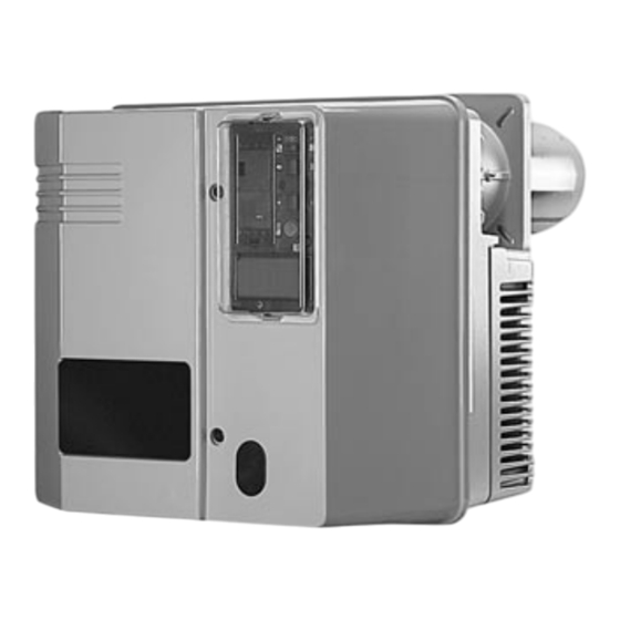
Seite 5: Brennerbeschreibung
Übersicht Brennerbeschreibung Feuerungsautomat Ionisationsbrücke Luftdruckwächter Motorschutzrelais Motorschutz Relais Brennermotor Zündtransformator (verdeckt) Schaltfeld Stellantrieb Luftklappe Flammrohr Brennerhaube Luftkasten 03/2005 - Art. Nr. 13 018 104A... -
Seite 6: Abmessungen
Übersicht Maßbild und Abmessungen G 05.700/1000 DUO PLUS mit Gasarmatur MBVEF 412 und MBVEF 420 MBVEF 412 Rp 1,1/4 Abstände Gasarmaturgruppe Für Servicearbeiten ist ein freier Montage sowohl links als auch rechts Abstand von min. 0,6m auf jeder Seite möglich. des Brenners sicherzustellen. - Seite 7 Übersicht Maßbild und Abmessungen G 05.1000 DUO PLUS mit Gasarmatur VGG 10 - Rp2 und VGF 10 - DN65 VGF 10 - DN65 Abstände Für Servicearbeiten ist ein freier Abstand von min. 0,6m auf jeder Seite des Brenners sicherzustellen. Gasarmaturgruppe Montage sowohl links als auch rechts möglich.
-
Seite 8: Funktion
Funktion Kompaktarmatur MBVEF Elektroanschluß des Gasdruckwächters (DIN 43650) Elektroanschluß der Magnetventile (DIN 43650) Gasdruckwächter Eingangsflansch Druckmeßnippel R1/8, vor Filter (beidseitig) Filter (unter Deckel) Typenschild Anschluß Luftdruckleitung pL, R 1/8 Einstellschraube für Verhältnis V Druckmeßnippel pe, vor Ventil 1, beidseitig Gasdruckmeßnippel M4 nach Ventil 2 Einstellschraube Nullstellung N Die Gaskompaktarmatur MBVEF ist die... -
Seite 9: Gasarmatur Vgg/Vgf Mit Skp 70 Regler
Funktion Gasarmatur VGG/VGF mit SKP 70 Regler pBr (pG)=Impulsleitung Gas pF = Impulsleitung Feuerraum pL = Impulsleitung Luft Einstellschraube (Luftüberschuß) Einstellschraube (Verhältnis Gas/Luft) Der SKP-Regler kombiniert mit einem VGG/F Ventil sichert ein konstantes Verhältnis zwischen Gas- und Luft- Einstell-Index Einstell-Index des D-Wertes durchsatz mit einstellbarem Verhältnis des Verhältnis-... -
Seite 10: Schaltfeld Tc
Funktion Schaltfeld TC Funktion Genormte Einbaustellen 48x48 oder 48x96 mm für den Einbau eines Leistungsreglers (Option) A4.1 Einbaustelle mit Klips für Anzeige- einheit B10 Messbrücke [µA DC] für Zellen- strom, Anordnung neben dem Motorschütz F10 Sicherung Hauptschalter Ein, grüne Kontroll-Lampe H10 leuchtet Wahl der Leistungsregelung Handbetrieb... -
Seite 11: Kenndaten Des Feuerungsautomaten Sg 513 Programmablauf Des Feuerungsautomaten
Funktion Kenndaten des Feuerungsautomaten SG 513 Programmablauf des Feuerungsautomaten Der Gasfeuerungsautomat SG 5xx steuert und Drücken Sie auf … führt zu … überwacht den Gebläsebrenner. Durch den den Knopf R mikroprozessor-gesteuerten Programmablauf ergeben sich äußerst stabile Zeiten, unabhängig während ... von Schwankungen der Netzspannung oder der …... -
Seite 12: Brennermontage
Montage Brennermontage Montage Brennkopf liche Maß ausschneiden. · Brennkopf mit 4 Sechskantmuttern · Brennerplatte/Kesseltüre gemäß nebenstehender Zeichnung vorberei- M10 befestigen. · Der Raum zwischen Flammrohr und ten. · Innendurchmesser a Ø von 172 bis Türisolierung ist mit feuerfestem 195 mm festlegen. Material auszukleiden ·... -
Seite 13: Prüfung / Einstellung
Montage Prüfung / Einstellung Mischeinrichtung für Erdgas / Flüssiggas Kontrolle der Mischeinrichtung · Einstellungen der Zündelektroden und der Ionisationssonde / Stau- scheibe überprüfen und justieren. Ionisationssonde / Zündelektrode Empfohlene Einstellung für Erdgas Erdgas Auf der mit A bezeichnete Gasdüse sind 5 nach außen und 1 nach innen gerichteter Schlitz durch die Schiebe- hülse E offen zu halten. -
Seite 14: Gasversorgung, Elektrische Versorgung
Montage Gasversorgung Elektrische Versorgung Prüfung vor Inbetriebnahme Allgemeine Vorschriften für die Gas- Bei der Inbetriebnahme des Brenners wird gleichzeitig die Anlage unter der versorgung · Der Anschluss der Gasarmatur an Verantwortung des Installateurs oder seines Stellvertreters abgenommen. Er das Gasnetz darf nur von einer allein kann gewährleisten, dass die anerkannten Fachkraft durchgeführt Anlage den geltenden Normen und... -
Seite 15: Brennereinstelldaten
Inbetriebnahme Brennereinstelldaten Luftregulierung Luftklappenstellung (°) Maß Brenner- leistung Zündlast Vollast Nocke III Nocke I 10° 25° G 05.700 DUO PLUS 10° 40° 10° 50° 10° 40° 10° 60° G 05.1000 DUO PLUS 1000 10° 90° Obige Einstelldaten sind Grundeinstellungen. Die Werkseinstelldaten sind fett umrandet. Mir diesen Einstellungen kann im Normalfall der Brenner in Betrieb genommen werden. - Seite 16 Inbetriebnahme Luftregulierung Luftregulierung über Luftklappe Diese wird über den Stellmotor Y10 angetrieben. Die Position der Luftklappe wird durch Einstellung der Nocken I - IV festgelegt. Stellindex der Nocken Vier einstellbare Nocken Schlüssel zur Nockeneinstellung Scheibe mit Skala ; gibt Stellung der Luftklappe an Knopf zur Entkupplung der Luft- klappe von Stellantrieb Anschlußleiste...
-
Seite 17: Einregulierung Des Brenners
Inbetriebnahme Einregulierung des Brenners Einregulierung des Brenners – bei MB VEF Ventil auf Schraube V hältnis R, beim MB VEF-Ventil das · Gaskugelhahn öffnen. wirken. Höheres CO in Richtung Verhältnis V im gewünschten Sinne · Gas- und Luftdruckwächter auf Mini- grösserer Skalenwert. -
Seite 18: Einstellung Gasdruckwächter / Luftdruckwächter . 20 Funktionskontrolle
Inbetriebnahme Einstellung Gasdruckwächter, Luftdruckwächter Funktionskontrolle Einstellung Gasdruckwächter · Zur Einstellung Abschaltdruckes : Deckel des Gasdruckwächters abnehmen. · Brenner starten und Gasdruck vor Armatur durch androsseln des Kugelhahns auf gewünschten Abschaltwert einstellen. · Einstellscheibe im Uhrzeigersinn drehen, bis Gasdruckwächter Brenner abschaltet. Einstellung Luftdruckwächter ·... -
Seite 19: Wartung
Service Wartung Servicearbeiten an Kessel und Brenner führt ausschließlich die geschulte Fachkraft durch. Um eine turnusgemäße Durchführung der Servicearbeiten zu gewährleisten sollte dem Betreiber der Anlage der Abschluß eines Wartungsvertrages empfohlen werden. · Vor Wartungs- und Reinigungsarbei- ten, Strom abschalten. ·... - Seite 20 Service Wartung Flammrohr demontieren Ventile Filteraustausch Gas Dieser Arbeitsvorgang macht entweder Die Ventile erfordern keine besondere Der Filtereinsatz muß einmal jährlich das Öffnen der Feuerraumtür oder die Wartung. kontrolliert und wenn verschmutzt aus- Demontage des Brenners erforderlich. Es ist keine Reparatur an einem Ventil getauscht werden.
-
Seite 21: Störungsbeseitigung
Service Störungsbeseitigung Ursachen und Beseitigung von Wenn die Störung weiter besteht: Nur Originalersatzteile · Die vom Feuerungsautomat abgege- Störungen verwenden. Bei Störungen müssen die grundsätzli- benen Blink-Codes beachten und chen Voraussetzungen zum ordnungs- ihre Bedeutung aus nachstehender Hinweis: gemäßen Betrieb kontrolliert werden: Tabelle entnehmen. - Seite 45 03/2005 - Art. Nr. 13 018 104A...
- Seite 46 03/2005 - Art. Nr. 13 018 104A...
- Seite 47 03/2005 - Art. Nr. 13 018 104A...
- Seite 48 03/2005 - Art. Nr. 13 018 104A...
- Seite 49 03/2005 - Art. Nr. 13 018 104A...
- Seite 50 03/2005 - Art. Nr. 13 018 104A...
- Seite 51 03/2005 - Art. Nr. 13 018 104A...
- Seite 52 03/2005 - Art. Nr. 13 018 104A...
- Seite 53 03/2005 - Art. Nr. 13 018 104A...
- Seite 54 Maintenance parts are parts which should be replaced on a preventive basis during maintenance when reassembling disassembled parts (sealing components for example).. For wear parts and maintenance parts, ELCO’s performance warranty for them over time under commercial conditions does not apply.
- Seite 55 03/2005 - Art. Nr. 13 018 104A...
- Seite 56 Adresse Service-Hotline ELCO Austria GmbH Aredstr.16-18 0810-400010 2544 Leobersdorf ELCO Belgium n.v./s.a. Pontbeeklaan-53 02-4631902 1731 Zellik ELCOTHERM AG 0848 808 808 Sarganserstrasse 100 7324 Vilters ELCO GmbH Dreieichstr.10 0180-3526180 64546 Mörfelden-Walldorf ELCO France 18 rue des Buchillons 0450877624 74106 Annemasse ELCO-Rendamax B.V.