Herunterladen Inhalt Inhalt Diese Seite drucken
Inhaltsverzeichnis

Werbung

Verfügbare Sprachen
  • DE

Verfügbare Sprachen

  • DEUTSCH, seite 1
Montageanleitung | Assembly instructions | Instructions de montage
Istruzioni di montaggio | Instrucciones de montaje | Monteringsanvisning
549411-001-AB
2023-03; Replaces: 2021-05
DE/EN/FR/IT/ES/SV
AVENTICS™ 652/653
Durchflusssensor
Flow sensor
Capteur de débit
Flussometro
Sensor de caudal
Flödessensor

Werbung

Inhaltsverzeichnis

Fehlerbehebung

loading

Inhaltszusammenfassung für Emerson AVENTICS 652

  • Seite 1 Montageanleitung | Assembly instructions | Instructions de montage Istruzioni di montaggio | Instrucciones de montaje | Monteringsanvisning 549411-001-AB 2023-03; Replaces: 2021-05 DE/EN/FR/IT/ES/SV AVENTICS™ 652/653 Durchflusssensor Flow sensor Capteur de débit Flussometro Sensor de caudal Flödessensor...
  • Seite 2: Inhaltsverzeichnis

    Inhaltsverzeichnis Zu dieser Dokumentation ........................................Gültigkeit der Dokumentation ......................................Zusätzliche Dokumentationen ......................................Verwendete Abkürzungen ........................................ Sicherheit ............................................Zu diesem Kapitel ..........................................Bestimmungsgemäße Verwendung....................................Nicht bestimmungsgemäße Verwendung ..................................Pflichten des Betreibers........................................Qualifikation des Personals ....................................... Gefahrenquellen ..........................................2.6.1 Verletzungsgefahr......................................2.6.2 Materialschäden......................................... Lieferumfang.............................................
  • Seite 3 9.1.2 Vorgehen ........................................... Reinigung ............................................9.2.1 Allgemeine Vorgaben......................................9.2.2 Vorgehen ........................................... Wartung ............................................Nach der Instandhaltung........................................10 Demontage und Austausch........................................ 10.1 Vorbereitung ............................................ 10.2 Vorgehen............................................11 Daten und Parameter ........................................11.1 Hinweise zur Sicherheit ........................................11.2 Allgemeine Einstellungen........................................11.3 Einstellungen für Variante IO-Link ..................................... 11.4 Einstellungen für Variante Ethernet....................................
  • Seite 4: Zu Dieser Dokumentation

    Hinweise 1 Zu dieser Dokumentation • Das Produkt ist für den Einbau in Wartungseinheiten der Serien 652 und 653 Lesen Sie diese Dokumentation vollständig und insbesondere das Kapitel g 2. Si- oder zur Montage als Einzelgerät mit Hilfe von Befestigungswinkeln vorgese- cherheit, bevor Sie mit dem Produkt arbeiten. hen.
  • Seite 5: Lieferumfang

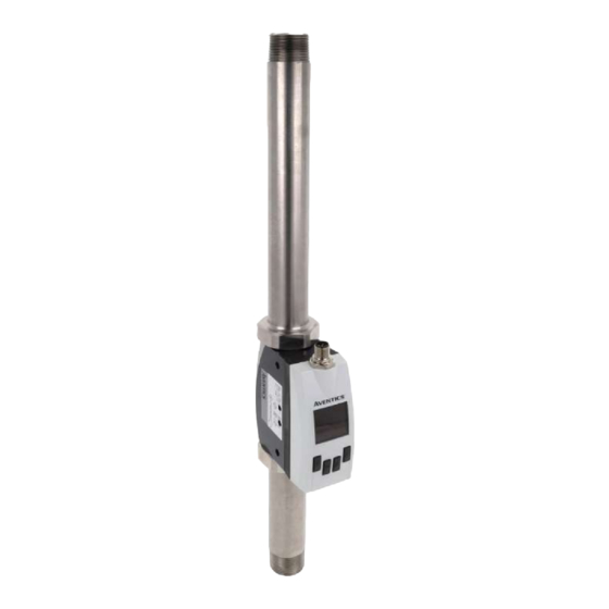
    • Sicherstellen, dass die neueste freigegebene Software-Version und Firmware- 5.3 Produktübersicht Version auf allen mit dem Netz verbundenen Produkten installiert sind. 5.3.1 Ausführungen 3 Lieferumfang • 1x Montageanleitung • 1x Filter-Produktvariante oder 1x Rohr-Produktvariante (siehe Bestellung) 4 Transport und Lagerung Abb. 1: Bestandteile im Überblick 4.1 Produkt transportieren 1 Ethernet-Produktvariante: M12-Ste-...
  • Seite 6: Bedienfunktionen Und Bedienelemente

    • Überwachung von Lecks in Druckluftleitungen an Maschinen • Messung von inerten Gasen bei der Verpackung von Lebensmitteln 6 Montage und Installation Bevor Sie mit dem Einbau anfangen: Machen Sie sich möglichst frühzeitig im Vor- feld mit den grundlegenden Vorgaben für die Montage vertraut. Siehe g 6.1 Pla- nung und g 6.2 Vorbereitung.
  • Seite 7: Hinweise

    2. Produkt auf Transportschäden und Lagerungsschäden prüfen. Vorgehen Ein beschädigtes Produkt darf nicht montiert werden. Beschädigte Produkte zusammen mit den Lieferunterlagen zurückschicken. Siehe g 4.3 Produkt zu- rücksenden. 3. Benötigtes Zubehör, Material und Werkzeug bereitlegen. 6.2.2 Hinweise • Bei Verlängerungsleitungen mit offenem Ende darauf achten, dass sich blanke Aderenden nicht berühren.
  • Seite 8: Montage Mit Verblockungssatz

    6.3.3 Montage mit Verblockungssatz • Variante IO-Link: 5-poliger M12x1-Anschluss. Siehe g 6.4.1 Anschluss mit 5-poligem M12-Ste- cker. • Variante Ethernet: 8-poliger M12x1-Anschluss. Siehe g 6.4.2 Anschluss mit 8-poligem M12-Ste- cker. 6.4.1 Anschluss mit 5-poligem M12-Stecker 1. M12x1-Stecker des Verbindungskabels CON-RD auf den Anschluss schrauben. Siehe g Abb. 1.
  • Seite 9: Inbetriebnahme

    Anschließend kann der Zugriff durch einen Sicherheitscode geschützt werden. Kontakt RJ45 Aderfarbe Identifikation 10/100 Mbit Weitere Informationen zu Konfigurationsmöglichkeiten finden Sie im Kapitel Da- (M12) ten und Parameter. Siehe g 11. Daten und Parameter. Grün RX (-) - POE RxData- Weiß/blau POE+ Blau POE+ 9 Instandhaltung Weiß/braun...
  • Seite 10: Wartung

    Ziel Untermenü Option 9.3 Wartung Pin für Bedienschutz bzw. Ma- Display Pin 4-stellige Pin vergeben Unter normalen Umgebungsbedingungen ist das Produkt wartungsfrei. nipulationsschutz vergeben 9.4 Nach der Instandhaltung Display Units MassFlowRat kg / h Wenn keine Schäden festgestellt wurden und der Betreiber keine Störungen ge- kg / min g / s meldet hat, kann das Produkt wieder an die Stromversorgung angeschlossen und...
  • Seite 11 Ziel Untermenü Option ScreenSaver Offset/Nullpunktverschie- Pressure/Temperature Option Offset auswählen und 1 min 2 min bung einstellen Offset/Nullpunkteverschie- 5 min bung einstellen 10 min Signalqualität wählen SigQuality Zwischen SigQua1, SigQua2, 30 min 60 min SigQua3 und SigQua4 aus- abort store wählen. Qualität ist jeweils auf 100 % eingestellt.
  • Seite 12 Pressure Offset ##.# bar Statistics View max, mean, min values: MassFlowRate abort store Pressure Temperature LastReset Filter VolumetricFlowRate (read only) 100 ms FlowVelocity 200 ms 500 ms abort store Reset (action required) abort store 10 s abort store Abb. 16 Temperature Offset ##.#°C Counter...
  • Seite 13: Einstellungen Für Variante Io-Link

    System Service #_#_#_# Screen 1.1 Screen 2.1 Events Status Signal abort store (Kg/h) Display 1 Top 60 min (m/s) Display 1 Btm (m/s) FactReset (action required) abort store Screen 1.2 Screen 2.2 Info (m³) Display 2 Top Signal Quality SerialNumber (m³/h) Display 2 Btm (read only) Screen 1.3...
  • Seite 14: Einstellungen Für Variante Ethernet

    11.4 Einstellungen für Variante Ethernet Q2 Menu Function Switch Frequency Die Einstellungen gelten für alle Varianten des Produkts mit dem elektrischen An- Pulse schluss Ethernet. Analog abort store Ethernet Mode Switch Hyst Volumetric Flowrate Ziel Untermenü Option Switch Hyst Temperature Switch Hyst Pressure Statische oder dynamische DHCP Mode...
  • Seite 15: Entsorgung

    OPC UA State Active Send Unit Active Inactive Inactive abort store abort store Port ##### MassFlowRate Active Inactive abort store abort store User # ... # FlowVelocity Active abort store Inactive Password # ... # abort store abort store VolFlowRate Active Inactive Abb. 24...
  • Seite 16: Fehlerbilder

    Energy Counter off - Air only Medium = Air Formel für Energiezähler nur Dieses Kapitel enthält einen Auszug der wichtigsten Technischen Daten. Weitere für Luft hinterlegt, daher keine Technische Daten finden Sie auf der Produktseite im Emerson Store. Funktion. Allgemein Voltage low for Q1/2 Spannung an Q1/2 zu niedrig.
  • Seite 17: Ersatzteile

    MBE Rohr-Produktvariante • ±3 % des Messwerts + 0,3 % des Standard- MBE 15 Ersatzteile • ±8 % des Messwerts + 1 % Hinweise zu Ersatzteilen finden Sie auf der Produktseite im Emerson Store. des erweiterten MBE Reproduzierbarkeit ±1,5 % des Messwerts Ansprechzeit (T90) < 0,3 s 16 Zubehör...
  • Seite 18 Contents About this documentation......................................... Documentation validity ........................................Additional documentation ........................................ Abbreviations used ........................................... Safety ..............................................About this chapter ..........................................Intended use ............................................. Improper use ............................................ Obligations of the operator....................................... Personnel qualifications ........................................Hazards............................................. 2.6.1 Danger of injury ......................................... 2.6.2 Material damage ........................................ Scope of delivery ..........................................
  • Seite 19 9.1.2 Procedure .......................................... Cleaning............................................9.2.1 General requirements ......................................9.2.2 Procedure .......................................... Maintenance ............................................. After service............................................10 Disassembly and exchange ........................................ 10.1 Preparation ............................................10.2 Procedure ............................................11 Data and parameters ......................................... 11.1 Notes on safety ..........................................11.2 General settings..........................................11.3 Settings for the IO-Link variant ......................................11.4 Settings for the Ethernet variant .......................................
  • Seite 20: About This Documentation

    1 About this documentation 2.3 Improper use Read this documentation completely, especially chapter g 2. Safety before work- The product is not intended for use in explosive areas (explosion protection). ing with the product. These instructions contain important information on the safe and appropriate as- 2.4 Obligations of the operator sembly, operation, and maintenance of the product and how to remedy simple •...
  • Seite 21: Transport And Storage

    4 Transport and storage Series Product variant Interface Filter product variant IO-Link (A) 4.1 Transporting the product Ethernet (B) Pipe product variant IO-Link (A) Hazards during transportation Ethernet (B) • Proceed with caution and observe the information on the packaging when un- Filter product variant IO-Link (A) loading and transporting the packaged product to the destination.
  • Seite 22: Function And Application

    INFO: The display language is English and cannot be changed. • Maintain a minimum clearance of 150 mm for the transmitter unit of the product. Operating principle: • In default setting, the first press of a button always switches on the back- Ambient conditions ground illumination.
  • Seite 23: Assembly With Mounting Bracket

    • The inlet zones can be reduced by additionally installed flow conditioners. 6.3.2 Assembly with mounting bracket Flow conditioners create an additional pressure loss that can reduce the flow quantity. Table 3: Installation direction Type Pipe diameter = DN (3) Inlet zone (1) Outlet zone (2) Expansion 10 x DN...
  • Seite 24: Connection With 5-Pin M12 Plug

    Notes RJ45 • Circuits connected to the product must be SELV and PELV circuits. • Observe the correct supply voltage (material protection). • Operation only with protected low voltage (material protection). • Protection class III electric insulation (material protection). • If the product is exposed to strong electromagnetical fields: Use shielded ca- bles.
  • Seite 25: Operation

    • Check the product functions. 8 Operation 9.2 Cleaning 8.1 Basic requirements General requirements 9.2.1 General requirements • Operation only with protected low voltage (material protection). Cleaning intervals • Never switch off, modify or bypass safety devices. • The system owner specifies the cleaning intervals in line with the ambient •...
  • Seite 26 Display Pages Disp1 Top MassFlowRate Objective Submenu Option Pressure Temperature Set the units Units Select from the following menus: Energy Disp1 Btm Mass • MassFlowRate VolumetricFlowRate • FlowVelocity Volume Disp2 Top FlowVelocity • Volume • VolFlowRate Disp2 Btm • Mass •...
  • Seite 27 Objective Submenu Option Pressure Offset ##.# bar Set the reference standard Flow Select the RefCond option and abort store set the reference standard: Filter • ISO 2533 100 ms • ISO 1217 200 ms 500 ms • DIN 1945-1 • DIN 1343 • ISO 6358 10 s •...
  • Seite 28: Settings For The Io-Link Variant

    Statistics View max, mean, min values: System Service #_#_#_# MassFlowRate abort store Pressure Temperature LastReset FactReset (action required) VolumetricFlowRate (read only) abort store FlowVelocity abort store SerialNumber (read only) Reset (action required) abort store DevTag Fig. 16 abort store Counter AppTag abort store Objective...
  • Seite 29 Q2 Menu Function Switch Screen 1.1 Screen 2.1 Events Status Signal Frequency (Kg/h) Display 1 Top 60 min Pulse (m/s) Display 1 Btm (m/s) Analog abort store Screen 1.2 Screen 2.2 Info (m³) Display 2 Top Signal Quality Mode Switch Hyst Volumetric Flowrate (m³/h) Display 2 Btm Switch Hyst Temperature Switch Hyst Pressure...
  • Seite 30: Settings For The Ethernet Variant

    11.4 Settings for the Ethernet variant OPC UA State Active Inactive The settings apply to all variants of the product with Ethernet electrical connec- abort store tion. Port ##### Ethernet abort store Objective Submenu Option User # ... # Assign a static or dynamic ad- DHCP Mode Assign an address abort...
  • Seite 31: Disposal

    Message Description Remedy Send Unit Active Flow low Info Info: MBE -5 %. Increase MBE to the specified Inactive value. abort store Flow high Info Info: Standard MBE +5 %. Reduce the standard MBE to MassFlowRate Active the specified value. Inactive Temperature high Temperature too high.
  • Seite 32: Technical Data

    ±2 °C This section contains an excerpt of the most important technical data. Further Reproducibility ±0.5 °C technical data can be found on the product page in the Emerson store. Pressure measurement Measurement precision ≤ ±1.5 % of measurement range (in the range of General 10 … 30 °C)
  • Seite 33: Spare Parts

    • G1/2", G1" (in accordance with ISO 228-1) • 1/2" NPT, 1" NPT 15 Spare parts Information on spare parts can be found on the product page in the Emerson store. 16 Accessories Information on accessories can be found on the product page in the Emerson store.
  • Seite 34 Sommaire A propos de cette documentation...................................... Validité de la documentation ......................................Documentation supplémentaire ....................................... Abréviations utilisées ........................................Sécurité ............................................. À propos de ce chapitre........................................Utilisation conforme ......................................... Utilisation non conforme ........................................Obligations de l’exploitant ........................................ Qualification du personnel ........................................ Sources de danger ..........................................2.6.1 Risque de blessure......................................
  • Seite 35 9.1.2 Procédure .......................................... Nettoyage............................................9.2.1 Spécifications générales ..................................... 9.2.2 Procédure .......................................... Maintenance ............................................. Après l’entretien ..........................................10 Démontage et remplacement......................................10.1 Préparation ............................................10.2 Procédure ............................................11 Données et paramètres ........................................11.1 Consignes relatives à la sécurité ......................................11.2 Réglages généraux..........................................11.3 Réglages pour la variante Ethernet IO-Link ..................................
  • Seite 36: Propos De Cette Documentation

    Remarques 1 A propos de cette documentation • Le produit est destiné à une pose dans des unités de traitement de l’air des sé- Lire entièrement la présente documentation et en particulier le chapitre g 2. Sé- ries 652 et 653 ou comme appareil individuel à l’aide d’équerres de fixation. curité...
  • Seite 37: Fourniture

    • S’assurer que les dernières versions validées du logiciel et du progiciel sont 5.3 Aperçu du produit installées sur tous les produits connectés au réseau. 5.3.1 Versions Type de construction tuyau 652/653 3 Fourniture Type de construction filtre 652 • 1 Instructions de montage •...
  • Seite 38: Fonctions De Commande Et Éléments De Commande

    • Surveillance des fuites dans les conduites d’air comprimé des machines • Mesure des gaz inertes dans le conditionnement des aliments 6 Montage et installation Avant de commencer l’installation : se familiariser le plus tôt possible avec les spécifications de base pour le montage. Voir g 6.1 Planification g 6.2 Prépara- tion.
  • Seite 39: Remarques

    2. Vérifier un éventuel endommagement du produit lié au transport. Procédure Ne pas monter un produit endommagé. Retourner les produits endommagés avec les documents de livraison. Voir g 4.3 Retourner le produit. 3. Préparer les accessoires, le matériel et les outils requis. 6.2.2 Remarques •...
  • Seite 40: Montage Avec Un Kit De Montage En Batterie

    6.3.3 Montage avec un kit de montage en batterie Procédure Selon la variante, le produit est équipé sur sa face supérieure de l’un des raccords suivants pour l’alimentation en tension et les sorties : • Variante IO-Link : Raccord à 5 pôles M12x1. Voir g 6.4.1 Raccord avec connecteur à...
  • Seite 41: Mise En Service

    Tab. 5: Affectation des broches connecteur M12 à 8 pôles 8.2 Configurer le produit Contact RJ45 Couleur des Identification 10/100 Mbit Après raccordement de l’alimentation électrique, le produit peut être configuré. (M12) fils Les détails suivants peuvent être définis : Blanc/orange TX (+) + POE TxData+ •...
  • Seite 42: Procédure

    9.2.2 Procédure Objectif Sous-menu Option 1. Fermer toutes les ouvertures à l’aide de protections appropriées pour empê- Régler l’afficheur 2.1, 2.2 et 2.3 Pages Dans le menu DispHistory, sélection- cher le produit de nettoyage de pénétrer dans le système. ner les paramètres de l’afficheur Optimiser la lisibilité...
  • Seite 43 Objectif Sous-menu Option ScreenSaver Filtre de valeur moyenne pour Flow/Pressure/Temperature Sélectionner l’option Filter et 1 min 2 min l’ajustement de la valeur me- régler le filtre de valeur mesu- 5 min surée sur l’afficheur et la sor- rée 10 min 30 min 60 min Régler le décalage/l’offset du...
  • Seite 44 Pressure Offset ##.# bar Statistics View max, mean, min values: MassFlowRate abort store Pressure Temperature LastReset Filter VolumetricFlowRate (read only) 100 ms FlowVelocity 200 ms 500 ms abort store Reset (action required) abort store 10 s abort store Fig. 16 Temperature Offset ##.#°C Counter...
  • Seite 45: Réglages Pour La Variante Ethernet Io-Link

    System Service #_#_#_# Screen 1.1 Screen 2.1 Events Status Signal abort store (Kg/h) Display 1 Top 60 min (m/s) Display 1 Btm (m/s) FactReset (action required) abort store Screen 1.2 Screen 2.2 Info (m³) Display 2 Top Signal Quality SerialNumber (m³/h) Display 2 Btm (read only) Screen 1.3...
  • Seite 46: Réglages Pour La Variante Ethernet

    11.4 Réglages pour la variante Ethernet Q2 Menu Function Switch Frequency Les réglages s’appliquent à toutes les variantes du produit avec le raccord élec- Pulse trique Ethernet. Analog abort store Ethernet Mode Switch Hyst Volumetric Flowrate Objectif Sous-menu Option Switch Hyst Temperature Switch Hyst Pressure Affecter une adresse statique DHCP Mode...
  • Seite 47: Elimination

    OPC UA State Active Send Unit Active Inactive Inactive abort store abort store Port ##### MassFlowRate Active Inactive abort store abort store User # ... # FlowVelocity Active abort store Inactive Password # ... # abort store abort store VolFlowRate Active Inactive Fig. 24...
  • Seite 48: Erreurs Possibles

    Ce chapitre contient un extrait des principales données techniques. D’autres don- spécifiée. nées techniques sont disponibles sur la page dédiée au produit dans l’Emerson Voltage low for Q2/a, Qa Tension à Q2/a, Qa trop basse. Mettre la tension à la valeur Store.
  • Seite 49: Système Électrique

    Des informations relatives aux pièces de rechange figurent sur la page dédiée au Mesure de pression Précision de mesure ≤ ±1,5 % de la plage de mesure produit dans l’Emerson Store. (dans plage 10 ... 30 °C) Non-linéarité ≤ ±0,5 % de la plage de mesure Reproductibilité...
  • Seite 50 Indice Sulla presente documentazione......................................Validità della documentazione ......................................Documentazione aggiuntiva ......................................Abbreviazioni utilizzate ........................................Sicurezza ............................................Sul presente capitolo ........................................Uso a norma............................................Uso non a norma..........................................Obblighi del gestore.......................................... Qualifica del personale ........................................Fonti di pericolo ..........................................2.6.1 Pericolo di lesioni ....................................... 2.6.2 Danni materiali........................................
  • Seite 51 9.1.2 Procedura........................................... Pulizia ............................................... 9.2.1 Disposizioni generali ......................................9.2.2 Procedura........................................... Manutenzione........................................... Dopo la manutenzione........................................10 Smontaggio e sostituzione ........................................ 10.1 Preparazione............................................. 10.2 Procedura ............................................11 Dati e parametri ..........................................11.1 Indicazioni sulla sicurezza........................................11.2 Impostazioni generali........................................11.3 Impostazioni per la variante IO-Link ....................................11.4 Impostazioni per la variante Ethernet....................................
  • Seite 52: Sulla Presente Documentazione

    Indicazioni 1 Sulla presente documentazione • Il prodotto è previsto per il montaggio in gruppi di trattamento dell'aria della Leggere questa documentazione in ogni sua parte e in particolare il capitolo serie 652 e 653 o per il montaggio come dispositivo singolo con l'ausilio di g 2. Sicurezzaprima di adoperare il prodotto.
  • Seite 53: Panoramica Sul Prodotto

    3 Fornitura 5.3 Panoramica sul prodotto • 1x Istruzioni di montaggio 5.3.1 Esecuzioni • 1x variante di prodotto con filtro o 1x variante di prodotto con tubo (vedere ordinazione) Versione 652 con filtro Versione 652/653 con tubo 4 Trasporto e stoccaggio 4.1 Trasporto del prodotto Pericoli durante il trasporto •...
  • Seite 54: Montaggio E Installazione

    • Monitoraggio di perdite nelle condutture di aria compressa delle macchine • Misurazione dei gas inerti nel confezionamento di generi alimentari 6 Montaggio e installazione Prima di procedere al montaggio: prendere visione quanto prima delle disposizio- ni di base per il montaggio. Vedere g 6.1 Pianificazione e g 6.2 Preparazione.
  • Seite 55: Fissaggio Del Prodotto

    neggiati assieme alla documentazione di consegna. Vedere g 4.3 Restituire il Procedimento prodotto. 3. Tenere a disposizione gli accessori, il materiale e gli utensili necessari. 6.2.2 Indicazioni • Nel caso dei cavi di prolunga con estremità aperta assicurarsi che i terminali nudi dei conduttori non si tocchino. Se la tensione di alimentazione è inserita, sussiste il pericolo di cortocircuito (protezione antinfortunistica, protezione del materiale).
  • Seite 56: Collegamento Elettrico

    6.3.3 Montaggio con set per il montaggio in batteria Procedimento A seconda della variante, il prodotto dispone sul lato superiore di uno dei seguen- ti attacchi per l’alimentazione di tensione e le uscite: • Variante IO-Link: Attacco M12x1 a 5 poli. Vedere g 6.4.1 Attacco con connettore M12 a 5 poli.
  • Seite 57: Messa In Funzione

    Tab. 5: Piedinatura connettore M12 a 8 poli 8.2 Configurare il prodotto Contatto RJ45 Colore con- Identificazione 10/100 Mbit Dopo aver collegato l’alimentazione di tensione è possibile configurare il prodot- (M12) duttore to. Possono essere determinati i seguenti dettagli: Bianco/aran- TX (+) + POE TxData+ •...
  • Seite 58: Procedura

    9.2.2 Procedura Scopo Sottomenu Opzione 1. Chiudere tutte le aperture con dispositivi di protezione idonei per evitare che i Attivare lo screen saver ScreenSaver Impostare il tempo per l’attivazione detergenti possano penetrare nel sistema. dello screen saver Spegnimento del display AutoOff Impostare il tempo per lo spegni- 2.
  • Seite 59 Scopo Sottomenu Opzione ScreenSaver Impostare l’offset/offset zero Pressure/Temperature Selezionare l’opzione Offset e 1 min 2 min impostare l’offset/sposta- 5 min mento del punto zero 10 min Scegliere la qualità del segna- SigQuality Scegliere tra SigQua1, Sig- 30 min 60 min Qua2, SigQua3 e SigQua4.
  • Seite 60 Pressure Offset ##.# bar Statistics View max, mean, min values: MassFlowRate abort store Pressure Temperature LastReset Filter VolumetricFlowRate (read only) 100 ms FlowVelocity 200 ms 500 ms abort store Reset (action required) abort store 10 s abort store Fig. 16 Temperature Offset ##.#°C Counter...
  • Seite 61: Impostazioni Per La Variante Io-Link

    System Service #_#_#_# Screen 1.1 Screen 2.1 Events Status Signal abort store (Kg/h) Display 1 Top 60 min (m/s) Display 1 Btm (m/s) FactReset (action required) abort store Screen 1.2 Screen 2.2 Info (m³) Display 2 Top Signal Quality SerialNumber (m³/h) Display 2 Btm (read only) Screen 1.3...
  • Seite 62: Impostazioni Per La Variante Ethernet

    11.4 Impostazioni per la variante Ethernet Q2 Menu Function Switch Frequency Le impostazioni valgono per tutte le varianti del prodotto con attacco elettrico Pulse Ethernet. Analog abort store Ethernet Mode Switch Hyst Volumetric Flowrate Scopo Sottomenu Opzione Switch Hyst Temperature Switch Hyst Pressure Assegnare un indirizzo statico DHCP Mode...
  • Seite 63: Smaltimento

    OPC UA State Active Send Unit Active Inactive Inactive abort store abort store Port ##### MassFlowRate Active Inactive abort store abort store User # ... # FlowVelocity Active abort store Inactive Password # ... # abort store abort store VolFlowRate Active Inactive Fig. 24...
  • Seite 64: Errori

    Portare la tensione al valore Link. specificato. Il presente capitolo contiene un estratto dei principali dati tecnici. Per maggiori informazioni sui dati tecnici consultare la pagina del prodotto nell'Emerson Store. Q1 Config out of Range Punti di commutazione para- Parametrizzare i punti di com-...
  • Seite 65: Parti Di Ricambio

    Temperatura Precisione di misurazione ±2 °C Per maggiori informazioni sulle parti di ricambio consultare la pagina del prodot- Riproducibilità ±0,5 °C to nell'Emerson Store. Misurazione della pressio- Precisione di misurazione ≤ ±1,5 % del campo di misura- zione (nel range 10 … 30 °C) Non-linearità ≤ ±0,5 % del campo di misura-...
  • Seite 66 Índice Acerca de esta documentación ......................................Validez de la documentación ......................................Documentación adicional ......................................... Abreviaturas utilizadas ........................................Seguridad ............................................Acerca de este capítulo ........................................Uso previsto ............................................Uso no previsto ..........................................Obligaciones de la empresa explotadora................................... Cualificación del personal........................................Fuentes de peligro ..........................................2.6.1 Riesgo de lesiones ......................................
  • Seite 67 9.1.2 Procedimiento ........................................Limpieza ............................................9.2.1 Especificaciones generales ....................................9.2.2 Procedimiento ........................................Mantenimiento ..........................................Tras el mantenimiento ........................................10 Desmontaje y sustitución ........................................10.1 Preparación............................................10.2 Procedimiento ..........................................11 Datos y parámetros ........................................... 11.1 Notas sobre seguridad ........................................11.2 Ajustes generales ..........................................11.3 Ajustes de la variante IO-Link......................................
  • Seite 68: Acerca De Esta Documentación

    Notas 1 Acerca de esta documentación • El producto está previsto para su instalación en unidades de preparación de ai- Lea esta documentación por completo, especialmente el capítulo g 2. Seguri- re de las series 652 y 653 o para el montaje como aparato individual con ayu- dad, antes de empezar a trabajar con el producto.
  • Seite 69: Volumen De Suministro

    • Asegurarse de que se instala la última versión autorizada de software y firm- 5.3 Vista general de productos ware en todos los productos conectados en la red. 5.3.1 Versiones Versión para conducto 652/653 3 Volumen de suministro Versión para filtro 652 •...
  • Seite 70: Montaje E Instalación

    • Control de fugas en los conductos de aire comprimido de las máquinas • Medición de gases inertes en el envasado de productos alimenticios 6 Montaje e instalación Antes de comenzar con el montaje: familiarizarse lo antes posible con las especi- ficaciones básicas para el montaje.
  • Seite 71 2. Comprobar si el producto presenta daños de transporte y almacenamiento. Procedimiento No se puede montar un producto dañado. Devolver los productos dañados con los documentos de entrega. Véase g 4.3 Devolución del producto. 3. Disponer de los accesorios, los materiales y las herramientas necesarios. 6.2.2 Notas •...
  • Seite 72 6.3.3 Montaje con el juego de unión Procedimiento En función de la variante, el producto tiene una de las siguientes conexiones para la alimentación de tensión y las salidas en la parte superior: • Variante IO-Link: Conexión M12x1 de 5 polos. Véase g 6.4.1 Conexión con conector M12 de 5 polos.
  • Seite 73: Puesta En Servicio

    Tab. 5: Asignación de pines del conector M12 de 8 polos 8.2 Configurar el producto Contacto RJ45 Color del ca- Identificación 10/100 Mbit Después de conectar la alimentación de tensión, se puede configurar el produc- (M12) to. Se pueden establecer los siguientes detalles: Blanco/naran- TX (+) + POE TxData+...
  • Seite 74: Procedimiento

    Elemento auxiliar Objetivo Submenú Opción • Limpiar el producto únicamente con un paño húmedo. Ajustar la indicación Screen 1.1 Pages • Seleccionar Disp1Top • Utilizar únicamente agua y, en caso necesario, un producto de limpieza suave • Seleccionar Disp1Btm para la limpieza (protección del material). Ajustar la indicación Screen 1.2 Pages •...
  • Seite 75 Objetivo Submenú Opción ScreenSaver Filtro de media para el alisa- Flow/Pressure/Temperature Seleccionar la opción Filter y 1 min 2 min miento del valor medido en la ajustar el filtro de valor medi- 5 min pantalla y en la salida 10 min Ajustar offset/desplazamien- Pressure/Temperature Seleccionar la opción Offset y...
  • Seite 76 Pressure Offset ##.# bar Statistics View max, mean, min values: MassFlowRate abort store Pressure Temperature LastReset Filter VolumetricFlowRate (read only) 100 ms FlowVelocity 200 ms 500 ms abort store Reset (action required) abort store 10 s abort store Fig. 16 Temperature Offset ##.#°C Counter...
  • Seite 77: Ajustes De La Variante Io-Link

    System Service #_#_#_# Screen 1.1 Screen 2.1 Events Status Signal abort store (Kg/h) Display 1 Top 60 min (m/s) Display 1 Btm (m/s) FactReset (action required) abort store Screen 1.2 Screen 2.2 Info (m³) Display 2 Top Signal Quality SerialNumber (m³/h) Display 2 Btm (read only) Screen 1.3...
  • Seite 78: Ajustes De La Variante Ethernet

    11.4 Ajustes de la variante Ethernet Q2 Menu Function Switch Frequency Los ajustes se aplican a todas las variantes del producto con la conexión eléctrica Pulse Ethernet. Analog abort store Ethernet Mode Switch Hyst Volumetric Flowrate Objetivo Submenú Opción Switch Hyst Temperature Switch Hyst Pressure Asignar una dirección estática DHCP Mode...
  • Seite 79: Eliminación

    OPC UA State Active Send Unit Active Inactive Inactive abort store abort store Port ##### MassFlowRate Active Inactive abort store abort store User # ... # FlowVelocity Active abort store Inactive Password # ... # abort store abort store VolFlowRate Active Inactive Fig. 24...
  • Seite 80: Imágenes De Error

    Llevar la tensión al valor espe- Este capítulo incluye un resumen de los datos técnicos más importantes. Encon- IO-Link. cificado. trará más datos técnicos en la página del producto en Emerson Store. Q1 Config out of Range Puntos de conmutación para- Puntos de conmutación para-...
  • Seite 81: Piezas De Repuesto

    16 Accesorios Reproducibilidad ≤ ±0,2 % del margen de medición MTTF > 50 años Encontrará indicaciones sobre accesorios en la página del producto en Emerson Store. Condiciones de referencia según DIN 1343: presión atmosférica 1,01325 bar a temperatu- ra absoluta del aire comprimido de 0 °C Descripción N.º de artículo Montaje Cable de unión, serie CON-RD, M12x1...
  • Seite 82 Innehåll Om denna dokumentation ........................................ Dokumentationens giltighet ......................................Ytterligare dokumentation ....................................... Förkortningar som används....................................... Säkerhet............................................Om detta kapitel ..........................................Ändamålsenlig användning....................................... Ej ändamålsenlig användning......................................Den driftsansvariges skyldigheter ..................................... Personalens kvalifikationer........................................ Farokällor............................................2.6.1 Risk för personskador ......................................2.6.2 Materialskador ........................................Leveransomfattning .......................................... Transport och förvaring ........................................
  • Seite 83 9.1.2 Tillvägagångssätt ....................................... Rengöring ............................................9.2.1 Allmänna föreskrifter ......................................9.2.2 Tillvägagångssätt ....................................... Underhåll ............................................Efter underhåll ..........................................10 Demontering och byte........................................10.1 Förberedelse ............................................. 10.2 Tillvägagångssätt ..........................................11 Data och parametrar ......................................... 11.1 Säkerhetsinformation ........................................11.2 Allmänna inställningar ........................................11.3 Inställningar för varianten IO-Link ..................................... 11.4 Inställningar för varianten Ethernet ....................................
  • Seite 84: Om Denna Dokumentation

    1 Om denna dokumentation 2.3 Ej ändamålsenlig användning Läs igenom denna anvisning ordentligt, i synnerhet kapitel g 2. Säkerhet innan Produkten är inte avsedd för användning i områden med explosionsrisk du arbetar med produkten. (explosionsskydd). Denna bruksanvisning innehåller viktig information för att montera, använda och underhålla produkten på...
  • Seite 85: Transport Och Förvaring

    4 Transport och förvaring Serie Produktvariant Gränssnitt Rörproduktvariant IO-Link (A) 4.1 Transportera produkten Ethernet (B) Filterproduktvariant IO-Link (A) Faror under transport Ethernet (B) • Var försiktig vid avlastning och transport av den förpackade produkten till Rörproduktvariant IO-Link (A) destinationen och beakta informationen på förpackningen. Ethernet (B) •...
  • Seite 86: Funktion Och Tillämpning

    • I grundinställningen tänds bakgrundsbelysningen alltid vid första Omgivningsförhållanden knapptrycket. • Mätmediet och omgivningsluften får inte kondensera. Se g 14. Tekniska • Gör inställningar i menyn genom att hålla valfri pilknapp intryckt i minst data. 2 sekunder. • Låt produkten acklimatisera sig några timmar före montering. Annars kan det •...
  • Seite 87: Montering Med Fästvinkel

    Tab. 3: Monteringsriktning 6.3.2 Montering med fästvinkel Rördiameter = DN (3) Inloppsavstånd Utloppsavstånd Utbyggnad 10 x DN 3 x DN Förträngning 10 x DN 3 x DN 90°-vinkel 20 x DN 5 x DN Två 90°-vinklar 25 x DN 5 x DN på en nivå Två 90 -vinklar på 30 x DN 5 x DN en nivå, T- koppling Bild 6: Montering med fästvinkel 1. Anpassa produkten med hänsyn till flödesriktningen för mätmediet (ingång till vänster, utgång till höger).
  • Seite 88: Anslutning Med 5-Polig M12-Kontakt

    Information RJ45 • Strömkretsar som ansluts till produkten ska vara SELV- och PELV- strömkretsar. • Se till att matningsspänningen är korrekt (skydd mot materialskador). • Drift får endast ske med skyddad lågspänning (skydd mot materialskador). • Elektrisk isolering i skyddsklass III (skydd mot materialskador). •...
  • Seite 89: Drift

    Detaljkontroll 8 Drift • Märkningar och varningar på produkten: den driftsansvarige ska omedelbart byta ut märkningar eller varningar som är svåra att tyda. 8.1 Grundläggande föreskrifter • Kontrollera tätningarna. Allmänna föreskrifter • Kontrollera att alla skruvförbindelser sitter fast ordentligt. • Drift får endast ske med skyddad lågspänning (skydd mot materialskador). •...
  • Seite 90 Display Pages Disp1 Top MassFlowRate Mål Undermeny Alternativ Pressure Temperature Ställa in enheter Units Välja mellan dessa menyer: Energy Disp1 Btm Mass • MassFlowRate VolumetricFlowRate • FlowVelocity Volume Disp2 Top FlowVelocity • Volume • VolFlowRate Disp2 Btm • Mass • Energy Disp3 Top •...
  • Seite 91 Mål Undermeny Alternativ Pressure Offset ##.# bar Ställa in referensnorm/ Flow Välja alternativet RefCond och abort store referensstandard ställa in referensnorm/ referensstandard: Filter 100 ms • ISO 2533 200 ms • ISO 1217 500 ms • DIN 1945-1 • DIN 1343 10 s • ISO 6358 abort store •...
  • Seite 92: Inställningar För Varianten Io-Link

    Statistics View max, mean, min values: System Service #_#_#_# MassFlowRate abort store Pressure Temperature LastReset FactReset (action required) VolumetricFlowRate (read only) abort store FlowVelocity abort store SerialNumber (read only) Reset (action required) abort store DevTag Bild 16 abort store Counter AppTag abort store Mål...
  • Seite 93 Q2 Menu Function Switch Screen 1.1 Screen 2.1 Events Status Signal Frequency (Kg/h) Display 1 Top 60 min Pulse (m/s) Display 1 Btm (m/s) Analog abort store Screen 1.2 Screen 2.2 Info (m³) Display 2 Top Signal Quality Mode Switch Hyst Volumetric Flowrate (m³/h) Display 2 Btm Switch Hyst Temperature Switch Hyst Pressure...
  • Seite 94: Inställningar För Varianten Ethernet

    11.4 Inställningar för varianten Ethernet OPC UA State Active Inactive Inställningarna gäller för alla varianter av produkten med den elektriska Ethernet- abort store anslutningen. Port ##### Ethernet abort store Mål Undermeny Alternativ User # ... # Tilldela statisk eller dynamisk DHCP Mode Tilldela adress abort...
  • Seite 95: Avfallshantering

    13.2 Felbeskrivningar Send Unit Active Inactive Felbilder för klassificeringen Info abort store Meddelande Beskrivning Åtgärder MassFlowRate Active Inactive Simulation active Simulering aktiv abort store (utgångssignal eller processtorhet). FlowVelocity Active Inactive Flow low Info Info: MBE -5 %. Öka MBE till det specificerade värdet.
  • Seite 96: Tekniska Data

    14 Tekniska data Temperatur Mätnoggrannhet ±2 °C Det här kapitlet innehåller ett utdrag från de tekniska data som är viktigast. Reproducerbarhet ±0,5 °C Ytterligare tekniska data finns på produktsidan i Emerson Store. Tryckmätning Mätnoggrannhet ≤ ±1,5 % av mätområdet (inom området 10–30 °C) Allmänt Icke-linjäritet ≤ ±0,5 % av mätområde...
  • Seite 97: Reservdelar

    • G1/2", G1" (motsvarande ISO 228-1) • 1/2" NPT, 1" NPT 15 Reservdelar Information om reservdelar finns på produktsidan i Emerson Store. 16 Tillbehör Information om tekniska data finns på produktsidan i Emerson Store. Beskrivning Artikelnummer Kabel, serie CON-RD, M12x1 R412027647 Röruppsättning, serie 652, rörproduktvariant, 1/2" G...
  • Seite 98 The Emerson logo is a trademark and service mark of Emerson Electric Co. AVENTICS is a mark Further addresses: of one of the Emerson Automation Solutions family of business units. All other marks are pro- www.emerson.com/contactus...

Diese Anleitung auch für:

Aventics 653

Inhaltsverzeichnis