AsViva MG5 Betriebsanleitung
Inhaltsverzeichnis
Verfügbare Sprachen
Verfügbare Sprachen
Quicklinks
Inhaltsverzeichnis

Verwandte Anleitungen für AsViva MG5


Inhaltszusammenfassung für AsViva MG5
- Seite 1 BETRIEBSANLEITUNG / MANUAL VERSION: I-BU www.AsVIVA.de...
-
Seite 2: Inhaltsverzeichnis
INHALTSVERZEICHNIS GEWÄHRLEISTUNGSBESTIMMUNGEN ....................3 WICHTIGE HINWEISE ZU IHREM PRODUKT ..................4 WICHTIGE SICHERHEITSHINWEISE ....................5 PRODUKTZEICHNUNG..........................7 EXPLOSIONSZEICHNUNG........................8 TEILELISTE ...............................9 MONTAGETEILE .............................10 SPEZIFIKATIONEN...........................12 MONTAGE ..............................13 AUFWÄRMEN UND DEHNEN ........................24 GEWÄHRLEISTUNGSRECHT ......................26 TABLE OF CONTENTS WARRANTY TERMS ..........................28 IMPORTANT INFORMATION ABOUT YOUR PRODUCT ..............29 IMPORTANT SAFETY INSTRUCTIONS ....................30 OVERVIEW ..............................32 EXPLODED DIAGRAM ...........................33 PARTS LIST .............................34... -
Seite 3: Gewährleistungsbestimmungen
Ersatzteilbestellungen und Reparaturaufträge richten Sie bitte unter Angabe der Kundennummer bzw. Rechnungsnummer an Ihren Händler oder direkt an uns. Unsere Serviceadresse: https://www.asviva.de/kontakt-formular Damit Ihnen unsere Service-Mitarbeiter optimal weiterhelfen können, beachten Sie bitte folgende Vorgehensweise: Ist ein bestimmtes Teil beschädigt? Teilen Sie uns bitte anhand der Teileiste die genaue Teilenummer mit. -
Seite 4: Wichtige Hinweise Zu Ihrem Produkt
WICHTIGE HINWEISE ZU IHREM PRODUKT Danke, dass Sie sich für eines unserer Produkte entschieden haben und für das damit entgegenge- brachte Vertrauen. Um Ihnen ein einwandfreies Produkt liefern zu können, obliegen alle unsere Pro- dukte und deren Produktion einer ständigen sowie ausführlichen Qualitätskontrolle. Sollte dennoch eine Fehlfunktion auftreten, Ihnen das Produkt nicht zusagen oder sollten Sie Anmer- kungen und Vorschläge haben, so bitten wir Sie nicht zu zögern und Kontakt mit unserem Support aufzunehmen, unter support@as-stores.com. -
Seite 5: Wichtige Sicherheitshinweise
WICHTIGE SICHERHEITSHINWEISE • Das Sicherheitsniveau des Gerätes kann nur gehalten werden, wenn es regelmäßig auf Schäden und Verschleiß geprüft wird. Dabei ist ein besonderes Augenmerk auf die die beweglichen Elemente zu richten. • Wenn Sie dieses Gerät weitergeben oder von einer anderen Person benutzen lassen, stellen Sie sicher, dass derjenige den Inhalt dieser Gebrauchsanleitung kennt. - Seite 6 WICHTIGE SICHERHEITSHINWEISE Bitte lesen Sie die Anleitung genau durch, bevor Sie mit den Zusammenbau beginnen! Achten Sie beim Anziehen der Schraubverbindungen darauf, dass der Bewegungsablauf nicht durch zu festes anziehen beeinträchtigt wird. Bewegliche Gelenkteile ( Gleitträger usw. ) müssen von Zeit zu Zeit mit handelsüblichem Schmierfett eingefettet werden.
-
Seite 7: Produktzeichnung
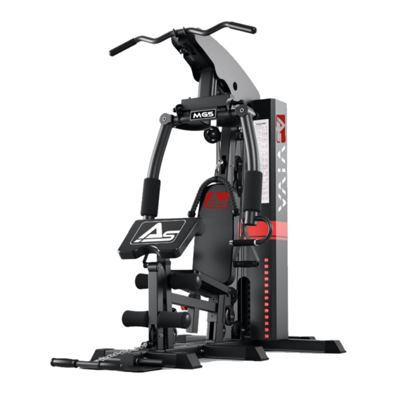
PRODUKTZEICHNUNG... -
Seite 8: Explosionszeichnung
EXPLOSIONSZEICHNUNG... -
Seite 9: Teileliste
TEILELISTE Teil Beschreibung Menge Teile Nr. Beschreibung Menge Rear Base Frame 53-1 Pulley Bracket Front Base Frame 53-2 Pulley Bracket Low Row Base Frame 53-3 Bracket Rear T Base Frame 53-4 Crossed Double Floating Pulley Bracket Foot Plate 53-5 L-shaped Pin Left&Right Base Frame 53-8 Axle (57 mm) -
Seite 10: Montageteile
MONTAGETEILE... - Seite 11 MONTAGETEILE...
-
Seite 12: Übersicht
ÜBERSICHT SPEZIFIKATIONEN • Maße: 208 x 140 x 210 cm • Einzelmaß Sitz: 24,5 x 39 x 5 cm • Einzelmaß Rückenlehne: 31 x 60 x 5,5 cm • Einzelmaß Armlehne: 31 x 60 x 5,5 cm • Gewicht: 156 kg •... -
Seite 13: Montage
MONTAGE SCHRITT 1 1. Verbinden Sie zunächst den Hauptrahmen (2) und den hinteren T-Rahmen (4) mit dem hinteren Verbindungsrahmen (1). Befestigen Sie diese mit einer Schraube (56-1), einer Unterlegscheibe (56-12) und einer Mutter (56-14). 2. Befestigen Sie den linken und rechten Rahmen (6) an den Hauptrahmen (2). Sichern Sie diese mit einer Schraube (56-1), einer Unterlegschraube (56-12) und einer Mutter (56-14). - Seite 14 MONTAGE SCHRITT 2 1. Schieben Sie zunächst die Gummipuffer (54-1) von unten auf die Führungsstangen (7). Setzen Sie die Führungsstangen (7) in die Löcher des hinteren Verbindungsrahmens (1) ein und befestigen Sie diese mit zwei Schrauben (56-3) und zwei Unterlegscheiben (56-12). 2.
- Seite 15 MONTAGE SCHRITT 3 1. Befestigen Sie den vertikalen Rahmen (10) am Hauptrahmen (2) und sichern Sie beiden Teile mit zwei Unterlegscheiben (56-12) und zwei Muttern (56-14). 2. Befestigen Sie die Hauptsitzstütze (11) am Hauptrahmen (2) und sichern Sie diese ebenfalls mit zwei Unterlegscheiben (56-12) und zwei Muttern (56-14).
- Seite 16 MONTAGE SCHRITT 4 1. Verbinden Sie den oberen Rahmen (13) mit den Führungsstangen (7) und sichern diese mit Schrau- ben (54) und Unterlegscheiben (67). Befestigen Sie nun den oberen Rahmen (13) am vertikalen Rahmen (10) mit Hilfe von Schrauben (56-1), Unterlegscheiben (56-12), Muttern (56-14) und einem Verbinder (53-3).
- Seite 17 MONTAGE SCHRITT 5 1. Fädeln Sie alle Kabel (22-1, 22-2 und 22-3) wie in der Abbildung dargestellt durch die jeweiligen Führungen. Hinweis: Machen Sie erst mit Schritt 2 weiter, wenn alle Kabel eingefädelt sind. 2. Montieren Sie die Riemenscheiben (23) wie in der Abbildung dargestellt. 3.
- Seite 18 MONTAGE SCHRITT 6 1. Fixieren Sie nun alle Teile mit den entsprechenden Schrauben. Richten Sie sich hierbei nach der Abbildung in Schritt 6.
- Seite 19 MONTAGE SCHRITT 7 1. Befestigen Sie die Rückenauflage (19) am vertikalen Rahmen (10) und sichern Sie diese mit zwei Schrauben (56-9) und Unterlegscheiben (56-12). 2. Legen Sie den Sitz (20) auf den Sitzständer (17) und sichern Sie diesen mit Schrauben (56-8) und Unterlegscheiben (56-12).
- Seite 20 MONTAGE SCHRITT 8 1. Befestigen Sie die obere Rahmenabdeckung (48) am oberen Rahmen (13) und am vertikalen Rahmen (10). Verwenden Sie hierfür Schrauben (56-7) und Unterlegscheiben (56-12).
- Seite 21 MONTAGE SCHRITT 9 1. Führen Sie zwei Schaumstoffrohre (28) zur Hälfte durch die Löcher der Beinentwickler (12) und der Hauptsitzhalterung (11). 2. Schieben Sie die Schaumstoffrollen (29) über beide Enden auf die Schaumstoffrohre (28). Stecken Sie anschließend die Verschlusskappen (54-3) an die Enden der Schaumstoffrollen (29).
- Seite 22 MONTAGE SCHRITT 10 1. Bringen Sie die linke Hantelscheibenabdeckung (30) und die rechte Hantelscheibenabdeckung (31) am oberen Rahmen (13), hinteren Verbindungsrahmen (1) und dem Hauptrahmen (2) an. Sichern Sie diese mit Schrauben (56-7) Unterlegscheiben (56-12) und Muttern (56-15).
- Seite 23 MONTAGE SCHRITT 11 1. Befestigen Sie nun die zwei Hantelscheibenabdeckungen mit den Schrauben (56-16) und (56-17). HINWEIS: • Bevor Sie das Fitnessgerät benutzen, ziehen Sie alle Schrauben und Muttern erneut fest. • Bevor Sie das Fitnessgerät benutzen, ziehen Sie das Stahlseil und die Riemenscheibe fest an.
-
Seite 24: Aufwärmen Und Dehnen
AUFWÄRMEN UND DEHNEN Aufwärmphase und Abkühlphase 1. Aufwärmphase 5 bis 10 Minuten Gymnastik und Stretching. Vorbereitung des Organismus auf die bevorstehende Traingsleistung. 2. Trainingsphase 15 bis 40 Minuten intensives aber nicht zu überfordendes Training 3. Abkühlphase 5 bis 10 Minuten Gymnastik und Stretching um die Muskulatur zu lockern und Muskelkater vorzu- beugen. - Seite 25 AUFWÄRMEN UND DEHNEN Dehnung der hinteren Oberschenkmuskulatur: Setzen Sie sich auf den Boden und strecken Sie Ihrrechtes Bein. Winkeln Sie Ihr linkes Bein so an, dass die Fußsohle die Innenseite Ihres rechten Oberschenkels berührt. Beugen Sie sich nun so weit wie möglich nach vorne und versuchen Sie, die Zehen an Ihrem rechten Bein zu berühren.
-
Seite 26: Gewährleistungsrecht
GEWÄHRLEISTUNGSRECHT Herzlichen Glückwunsch zu Ihrer Entscheidung zum Kauf eines Produkts aus dem Hause AsVIVA. Gemäß des zum 01. Januar 2002 geänderten europäischen Gewährleistungsrechts, steht Ihnen eine gesetzliche Gewährleistungsfrist von 2 Jahren zu. Die Gewährleistungsfrist beginnt mit der Übergabe der Ware durch den Fachhändler.