Dell Precision 3240 Compact Servicehandbuch
Vorschau ausblenden
Andere Handbücher für Precision 3240 Compact:
- Einrichtung und technische daten (38 Seiten) ,
- Installationshandbuch (31 Seiten) ,
- Servicehandbuch (90 Seiten)

Verwandte Anleitungen für Dell Precision 3240 Compact


Inhaltszusammenfassung für Dell Precision 3240 Compact
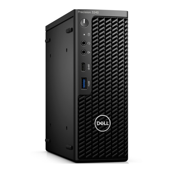
- Seite 1 Dell Precision 3240 Compact Service-Handbuch Vorschriftenmodell: D16S Vorschriftentyp: D16S001 August 2020 Rev. A00...
- Seite 2 Mit WARNUNG wird auf eine potenziell gefährliche Situation hingewiesen, die zu Sachschäden, Verletzungen oder zum Tod führen kann. © 2020 Dell Inc. oder ihre Tochtergesellschaften. Alle Rechte vorbehalten. Dell, EMC und andere Marken sind Marken von Dell Inc. oder entsprechenden Tochtergesellschaften. Andere Marken können Marken ihrer jeweiligen Inhaber sein.
-
Seite 3: Inhaltsverzeichnis
Intel UHD-Grafikkarte..............................11 NVIDIA Quadro P400..............................12 NVIDIA Quadro P620..............................12 NVIDIA Quadro P1000..............................13 Systemverwaltungsfunktionen............................13 Dell Client Command Suite für die bandinterne Systemverwaltung............14 USB-Funktionen................................... 14 Kapitel 3: Hauptkomponenten Ihres Systems................... 17 Kapitel 4: Ausbau und Wiedereinbau....................20 Empfohlene Werkzeuge..............................20 Screw List.....................................20... - Seite 4 Entfernen der internen Antenne..........................69 Einbauen der internen Antenne............................70 Kapitel 5: Fehlerbehebung......................72 Wiederherstellen des Betriebssystems..........................72 Zurücksetzen der Echtzeituhr (RTC)..........................72 Diagnose der Dell SupportAssist-Systemleistungsprüfung vor dem Start..............72 Ausführen der SupportAssist-Systemleistungsprüfung vor dem Systemstart............73 Verhalten der Diagnose-LED..............................73 Diagnose-Fehlermeldungen..............................75 Ein- und Ausschalten des WLAN............................78...
- Seite 5 Kapitel 6: Hilfe erhalten und Kontaktaufnahme mit Dell..............79 Inhaltsverzeichnis...
-
Seite 6: Kapitel 1: Arbeiten Am Computer
Sie dürfen nur Fehlerbehebungsmaßnahmen durchführen und Reparaturen vornehmen, wenn Sie durch das Dell Team für technische Unterstützung dazu autorisiert oder angeleitet wurden. Schäden durch nicht von Dell genehmigte Wartungsversuche werden nicht durch die Garantie abgedeckt. Lesen Sie die Sicherheitshinweise, die Sie zusammen mit dem Produkt erhalten haben bzw. -
Seite 7: Sicherheitsvorkehrungen
Da die Branche auf geringeren Leistungsbedarf und höhere Dichte drängt, ist der ESD-Schutz von zunehmender Bedeutung. Aufgrund der höheren Dichte von Halbleitern, die in aktuellen Produkten von Dell verwendet werden, ist die Empfindlichkeit gegenüber Beschädigungen durch elektrostatische Entladungen inzwischen größer als bei früheren Dell-Produkten. Aus diesem Grund sind einige zuvor genehmigte Verfahren zur Handhabung von Komponenten nicht mehr anwendbar. -
Seite 8: Esd-Service-Kit
● Gelegentlich: Gelegentliche Ausfälle machen etwa 80 Prozent der ESD-bezogenen Ausfälle aus. Die hohe Rate gelegentlicher Ausfälle bedeutet, dass auftretende Schäden in den meisten Fällen nicht sofort zu erkennen sind. Das DIMM erhält einen elektrostatischen Schock, aber die Ablaufverfolgung erfolgt nur langsam, sodass nicht sofort ausgehende Symptome im Bezug auf die Beschädigung erzeugt werden. -
Seite 9: Esd-Schutz - Zusammenfassung
Es wird empfohlen, dass Servicetechniker das herkömmliche verkabelte ESD-Erdungsarmband und die antistatische Matte jederzeit bei der Wartung von Dell Produkten verwenden. Darüber hinaus ist es äußerst wichtig, dass Techniker während der Wartung empfindliche Teile separat von allen Isolatorteilen aufbewahren und dass sie einen antistatischen Beutel für den Transport empfindlicher Komponenten verwenden. -
Seite 10: Kapitel 2: Technologie Und Komponenten
Technologie und Komponenten Dieses Kapitel erläutert die in dem System verfügbare Technologie und Komponenten. DDR4 DDR4-Speicher (Double Data Rate der vierten Generation) ist der schnellere Nachfolger der DDR2- und DDR3-Technologie und ermöglicht bis zu 512 GB Kapazität im Vergleich zu der maximalen Kapazität von 128 GB pro DIMM beim DDR3-Speicher. Synchroner DDR4-Speicher (Dynamic Random-Access) ist mit einer anderen Passung versehen als SDRAM und DDR. -
Seite 11: Grafikoptionen
Abbildung 3. Gebogene Kante Speicherfehler Speicherfehler auf der Systemanzeige 2,3 Fehlercode. Wenn alle Speicher ausfallen, lässt sich das LCD-Display nicht einschalten. Beheben Sie mögliche Speicherfehler, indem Sie funktionierende Speichermodule in Speicheranschlüssen an der Unterseite des Systems oder unter der Tastatur ausprobieren, wie in einigen tragbaren Systemen. ANMERKUNG: Der DDR4-Speicher ist in die Platine integriert und kein austauschbares DIMM-Modul (siehe Abbildung und Bezeichnung). -
Seite 12: Nvidia Quadro P400
Tabelle 2. Intel UHD-Grafikkarte 630 – Technische Daten (fortgesetzt) Beschreibung Technische Daten Maximale vertikale Bildwiederholfrequenz Bis zu 60 Hz je nach Auflösung NVIDIA Quadro P400 Tabelle 3. NVIDIA Quadro P400 – Technische Daten Beschreibung Werte GPU-Speicher 2 GB GDDR5 Speicherschnittstelle 64 Bit Speicherbandbreite Bis zu 32 Gbit/s... -
Seite 13: Nvidia Quadro P1000
Verwaltung in der Dell Client Command Suite enthalten sind. Bandinterne Verwaltung bedeutet, dass das System ein funktionsfähiges Betriebssystem hat und das Gerät mit einem Netzwerk verbunden ist, sodass es verwaltet werden kann. Die Dell Client Command Suite kann einzeln oder mit einer Systemverwaltungskonsole wie SCCM, LANDESK, KACE usw. eingesetzt werden. -
Seite 14: Dell Client Command Suite Für Die Bandinterne Systemverwaltung
Verwendung der Systemverwaltungsinfrastruktur des Benutzers, wie SCCM, nahtlos an den Endbenutzer geliefert. Dell Command | vPro Out of Band ist eine Konsole zur Erweiterung der Hardwareverwaltung auf Systeme, die offline sind oder deren Betriebssystem nicht erreichbar ist (exklusive Funktion von Dell). -
Seite 15: Geschwindigkeit
USB 3.2 Gen 1 (SuperSpeed USB) Viele Jahre lang war der USB 2.0 in der PC-Welt der Industriestandard für Schnittstellen. Das zeigen die etwa 6 Milliarden verkauften Geräte. Der Bedarf an noch größerer Geschwindigkeit ist jedoch durch die immer schneller werdende Computerhardware und die Nachfrage nach größerer Bandbreiten gestiegen. -
Seite 16: Kompatibilität
Mit den heutigen steigenden Anforderungen an Datenübertragungen mit High-Definition-Videoinhalten, Terabyte-Speichergeräten, digitalen Kameras mit hoher Megapixelanzahl usw. ist USB 2.0 möglicherweise nicht schnell genug. Darüber hinaus kam kein USB 2.0- Anschluss jemals in die Nähe des theoretischen maximalen Durchsatzes von 480 Mbit/s mit einer Datenübertragung von etwa 320 Mbit/s (40 MB/s) –... - Seite 17 Hauptkomponenten Ihres Systems...
-
Seite 18: Kapitel 3: Hauptkomponenten Ihres Systems
Hauptkomponenten Ihres Systems Hauptkomponenten Ihres Systems... - Seite 19 13. SSD-Laufwerk 14. Festplattenbaugruppe ANMERKUNG: Dell stellt eine Liste der Komponenten und ihrer Artikelnummern für die ursprüngliche erworbene Systemkonfiguration bereit. Diese Teile sind gemäß der vom Kunden erworbenen Gewährleistung verfügbar. Wenden Sie sich bezüglich Kaufoptionen an Ihren Dell Vertriebsmitarbeiter. Hauptkomponenten Ihres Systems...
-
Seite 20: Kapitel 4: Ausbau Und Wiedereinbau
Ausbau und Wiedereinbau Empfohlene Werkzeuge Für die in diesem Dokument beschriebenen Verfahren sind folgende Werkzeuge erforderlich: ● Kreuzschlitzschraubenzieher Nr. 1 ● Kleiner Schlitzschraubenzieher Screw List The following table shows the screw list and the image of the screws. Table 7. Screw list Component Screw type Quantity... -
Seite 21: Seitenabdeckung
Table 7. Screw list (continued) Component Screw type Quantity Image System board M3x4 #6-32 Riser card M3x5 Seitenabdeckung Removing the top cover (side bezel) Prerequisites 1. Follow the procedure in before working inside your computer. NOTE: Turn the optional SMA antenna downwards or remove it for convenient sliding of the top cover (side bezel). About this task The following image indicates the location of the top cover (side bezel) and provides a visual representation of the removal procedure. - Seite 22 Steps 1. Slide the top cover (side bezel) towards the back of the system unit. 2. Lift the top cover (side bezel) away from the system unit. Ausbau und Wiedereinbau...
-
Seite 23: Installing The Top Cover (Side Bezel)
Installing the top cover (side bezel) Prerequisites Wenn Sie eine Komponente austauschen, muss die vorhandene Komponente entfernt werden, bevor Sie das Installationsverfahren durchführen. About this task The following images indicate the location of the top cover (side bezel) and provide a visual representation of the installation procedure. Ausbau und Wiedereinbau... -
Seite 24: Top Cover (Side Bezel)
Steps 1. Align and place the top cover (side bezel) with the grooves on the chassis. 2. Slide the top cover (side bezel) towards to the front of the system unit to install it. Next steps NOTE: Turn the optional SMA antenna to a convenient angle after safely sliding back the top cover (side bezel) on the chassis. 1. - Seite 25 Steps 1. Loosen the thumbscrew (#6x32) that secures the side cover to the system. Ausbau und Wiedereinbau...
-
Seite 26: Installing The Side Cover
2. Slide the side cover towards the front of the system and lift the side cover from the system unit. Installing the side cover Prerequisites Wenn Sie eine Komponente austauschen, muss die vorhandene Komponente entfernt werden, bevor Sie das Installationsverfahren durchführen. -
Seite 27: Sma-Antenne
Steps 1. Align the side cover with the grooves on the chassis. 2. Slide the side cover towards the back of the system to install it. 3. Tighten the thumbscrew (#6x32) to secure the side cover to the system. Next steps 1. -
Seite 28: Installieren Der Sma-Antenne
Schritte 1. Drehen Sie die SMA-Antenne horizontal zu ihrem Anschluss am Gehäuse. 2. Lösen Sie die Mutter auf der Unterseite der SMA-Antenne, um die SMA-Antenne von der Systemeinheit zu trennen. 3. Entfernen Sie die SMA-Antenne von der Systemeinheit. Installieren der SMA-Antenne Voraussetzungen Wenn Sie eine Komponente austauschen, muss die vorhandene Komponente entfernt werden, bevor Sie das Installationsverfahren durchführen. - Seite 29 Info über diese Aufgabe Die folgende Abbildung zeigt die Position der SMA-Antenne und stellt das Verfahren zum Einbauen bildlich dar. Schritte 1. Richten Sie die Antenne am SMA-Anschluss der Systemeinheit aus und setzen Sie sie ein. 2. Ziehen Sie die Mutter an der Unterseite der SMA-Antenne fest, um die Antenne an der Systemeinheit zu befestigen. 3.
-
Seite 30: Frontverkleidung
Frontverkleidung Removing the front bezel Prerequisites 1. Follow the procedure in before working inside your computer. 2. Remove the side cover. 3. Remove the top cover (side bezel). About this task The following image indicates the location of the front bezel and provides a visual representation of the removal procedure. Steps 1. -
Seite 31: Festplattenbaugruppe
About this task The following image indicates the location of the front bezel and provides a visual representation of the installation procedure. Steps 1. Position the bezel to align the tabs with the slots on the chassis. 2. Press the bezel until the release tabs click into place. Next steps 1. -
Seite 32: Removing The Hard Drive Bracket
About this task The following images indicate the location of the hard drive assembly and provide a visual representation of the removal procedure. Steps 1. Press the release tabs on the hard drive assembly and slide it towards the front of the system to disconnect it from the connector on the system board. -
Seite 33: Installing The Hard Drive Bracket
About this task The following images indicate the location of the hard drive bracket and provide a visual representation of the removal procedure. Steps 1. Pull one side of the hard drive bracket to disengage the pins on the bracket from the slots on the drive. 2. -
Seite 34: Installing The 2.5 In. Hard Drive Assembly
Steps 1. Place the hard drive into the bracket. 2. Align and insert the pins on the drive bracket with the slots on the drive. NOTE: Note the orientation of the hard drive so that you can replace it correctly. Next steps 1. -
Seite 35: Ssd-Laufwerk
Steps 1. Insert the hard drive assembly into the slot on the system. 2. Slide the hard drive assembly towards the connector in the system board until the release tabs clicks into place. Next steps 1. Install the front bezel. 2. -
Seite 36: Installing The M.2 2280 Pcie Solid-State Drive
3. Remove the top cover (side bezel). 4. Remove the front bezel. 5. Remove the assembly. NOTE: This step is valid for system configuration that is shipped with 80 W CPU. 6. Remove the riser card. 7. Remove the hard-drive assembly. -
Seite 37: Wlan-Karte
Steps 1. Align the notch on the solid-state drive with the tab on the solid-state drive connector on the system board. 2. Insert the solid-state drive at a 45-degree angle into the solid-state drive connector. 3. Replace the screw (M2x3.5) that secures the M.2 2280 PCIe solid-state drive to the system board. Next steps 1. -
Seite 38: Installing The Wlan Card
Steps 1. Remove the (M2x3.5) screw that secures the WLAN card bracket to the system board. 2. Slide and lift the WLAN card bracket away from the WLAN card. 3. Disconnect the antenna cables from the WLAN card. 4. Slide and remove the WLAN card from the connector on the system board. Installing the WLAN card Prerequisites Wenn Sie eine Komponente austauschen, muss die vorhandene Komponente entfernt werden, bevor Sie das Installationsverfahren... - Seite 39 Steps 1. Connect the antenna cables to the WLAN card. The following table provides the antenna-cable color scheme for the WLAN card of your computer. Table 8. Antenna-cable color scheme Connectors on the Antenna-cable color Silkscreen marking wireless card △ (white triangle) Main White MAIN...
-
Seite 40: Lautsprecher
4. Install the side cover. 5. Follow the procedure in after working inside your computer. Lautsprecher Removing the speaker Prerequisites 1. Follow the procedure in before working inside your computer. 2. Remove the side cover. 3. Remove the top cover (side bezel). -
Seite 41: Lüfterbaugruppe
Steps 1. Align and insert the speaker into the slot and press it until the release tab clicks. 2. Connect the speaker cable to the system board. Next steps 1. Install the front bezel. 2. Install the top cover (side bezel). -
Seite 42: Installing The Fan Assembly
Steps NOTE: Unroute the speaker cable from the routing guide on the fan assembly. Press the blue tabs on both sides of the fan, and slide to lift the fan to release it from the system and turn it over. 2. - Seite 43 Steps 1. Connect the fan cable to the connector on the system board. 2. Press the release tab on the fan assembly and place it on the system up-side down until it clicks into place. NOTE: Route the speaker cable through the routing guides on the fan assembly. Next steps 1.
-
Seite 44: Knopfzellenbatterie
Knopfzellenbatterie Entfernen der Knopfzellenbatterie Voraussetzungen 1. Folgen Sie den Anweisungen unter Vor der Arbeit an Komponenten im Inneren des Computers. 2. Entfernen Sie die obere Abdeckung. 3. Entfernen Sie die Frontblende. 4. Entfernen Sie die Lüfterbaugruppe. ANMERKUNG: Durch das Entfernen der Knopfzellenbatterie wird das BIOS auf die Standardeinstellungen zurückgesetzt. Daher sollten Sie vor dem Entfernen der Knopfzellenbatterie die BIOS-Einstellungen notieren. -
Seite 45: Speichermodule
Schritte 1. Fügen Sie die Batterie mit dem positiven Pol (+)-Symbol nach oben ein und schieben Sie sie unter die Sicherungslaschen auf der positiven Seite des Anschlusses. 2. Drücken Sie die Batterie in den Anschluss, bis sie einrastet. Nächste Schritte 1. -
Seite 46: Installing The Memory Modules
Steps 1. Pull the securing clips from the memory module until the memory module pops-up. 2. Slide and remove the memory module from the memory-module slot. Installing the memory modules Prerequisites Wenn Sie eine Komponente austauschen, muss die vorhandene Komponente entfernt werden, bevor Sie das Installationsverfahren durchführen. -
Seite 47: Riser-Karte
Steps 1. Align the notch on the memory module with the tab on the memory-module slot. 2. Slide the memory module firmly into the slot at an angle and press the memory module down until it clicks into place. NOTE: If you do not hear the click, remove the memory module and reinstall it. -
Seite 48: Installing The Riser Card
Steps 1. Loosen the two screws (M2x4) that secure the riser card to the system chassis. 2. Lift the riser card from the system board. Installing the riser card Prerequisites Wenn Sie eine Komponente austauschen, muss die vorhandene Komponente entfernt werden, bevor Sie das Installationsverfahren durchführen. - Seite 49 Steps 1. Align the riser card and push it down on the PCIe connector of the system board. 2. Tighten the screws (M2x4) that secure the riser card to the system chassis. Next steps 1. Install the assembly. NOTE: This step is valid for system configuration that is shipped with 80 W CPU. 2.
-
Seite 50: Dell Ultra Speed-Laufwerk
This step is valid for system configuration that is shipped with 80 W CPU. 6. Remove the riser card. About this task The following images indicate the location of the Dell Ultra Speed Drive and provide a visual representation of the removal procedure. Ausbau und Wiedereinbau... -
Seite 51: Installing The Dell Ultra Speed Drive
1. Pull the metal tab to open the expansion card latch. 2. Slide the Dell Ultra speed drive along the edges of the riser card to release it from the riser card. 3. Flip over the Dell Ultra Speed Drive with SSD facing down. - Seite 52 Ausbau und Wiedereinbau...
-
Seite 53: Grafikkarte
Steps 1. Align the notch on the SSD with the tab on the solid-state drive connector on the Dell Ultra Speed Drive. 2. Install the standoff nut on the notch of the SSD. 3. Replace the single screw (M2x5) securing the standoff nut to the Dell Ultra Speed Drive. -
Seite 54: Installing The Graphics Card
Steps 1. Pull the metal tab to open the expansion card latch. 2. Slide the graphics card along the edges of the riser card to release it from the riser card. Installing the graphics card Prerequisites Wenn Sie eine Komponente austauschen, muss die vorhandene Komponente entfernt werden, bevor Sie das Installationsverfahren durchführen. - Seite 55 Steps 1. Replace the graphics card into the slot on the riser card until it clicks into place. 2. Close the expansion card latch and press it until it clicks into place. Next steps 1. Install the riser card. 2. Install the assembly.
-
Seite 56: Kühlkörper
Kühlkörper Removing the heat sink Prerequisites 1. Follow the procedure in before working inside your computer. 2. Remove the side cover. 3. Remove the top cover (side bezel). 4. Remove the front bezel. 5. Remove the assembly. About this task The following images indicate the location of the heat sink and provide a visual representation of the removal procedure. -
Seite 57: Installing The Heat Sink
Figure 5. Heat sink shipped with system configuration shipped with 80 W CPU Steps 1. Loosen the three captive screws that secure the heat sink to the system. NOTE: Loosen the screw in the sequential order (3,2,1) as printed on the heat sink. 2. - Seite 58 Figure 6. Heat sink shipped with system configuration shipped with 65 W CPU Ausbau und Wiedereinbau...
- Seite 59 Figure 7. Heat sink shipped with system configuration shipped with 80 W CPU Steps 1. Align the screws of the heat sink with the holders on the system board and place the heat sink on the processor. 2. Tighten the captive screws that secure the heat sink to the system board. NOTE: Tighten the screws in a sequential order (1,2,3) as printed on the heat sink.
-
Seite 60: Interposer-Modul
Interposer-Modul Removing the interposer module Prerequisites 1. Follow the procedure in before working inside your computer. 2. Remove the side cover. 3. Remove the top cover (side bezel) 4. Remove the front bezel. 5. Remove the assembly. NOTE: This step is valid for system configuration that is shipped with 80 W CPU. 6. -
Seite 61: Prozessor
Steps 1. Align and replace the interposer module on the system board. 2. Replace the single screw (M3x5) and connect the SATA cable to the connector on the system board and close the actuator. Next steps 1. Install the riser card. -
Seite 62: Installing The Processor
Steps 1. Press down and push the release lever away from the processor to release it from the securing tab. 2. Lift the lever upward to lift the processor cover. CAUTION: When removing the processor, do not touch any of the pins inside the socket or allow any objects to fall on the pins in the socket. - Seite 63 Steps 1. Align the pin-1 corner of the processor with the pin 1 corner of the processor socket, and then place the processor in the processor socket. NOTE: The pin-1 corner of the processor has a triangle that aligns with the triangle on the pin-1 corner on the processor socket. When the processor is properly seated, all four corners are aligned at the same height.
-
Seite 64: Systemplatine
Systemplatine Entfernen der Systemplatine Voraussetzungen 1. Folgen Sie den Anweisungen unter Vor der Arbeit an Komponenten im Inneren des Computers. 2. Entfernen Sie die Seitenabdeckung. 3. Entfernen Sie die obere Abdeckung. 4. Entfernen Sie die SMA-Antenne. 5. Entfernen Sie die Frontblende. 6. - Seite 65 Ausbau und Wiedereinbau...
-
Seite 66: Einbauen Der Systemplatine
Schritte 1. Entfernen Sie die einzelne Schraube (6-32) zur Befestigung des Festplattenhalters an der Systemplatine. 2. Heben Sie den Festplattenhalter von der Systemplatine. 3. Entfernen Sie die drei Schrauben (M3x4) und die drei Schrauben (6-32), mit denen die Systemplatine am Gehäuse befestigt ist. 4. - Seite 67 Ausbau und Wiedereinbau...
- Seite 68 Schritte 1. Senken Sie die Systemplatine in das System ab, bis die Anschlüsse auf der Rückseite der Systemplatine an den Steckplätzen im Gehäuse und die Schraubenöffnungen der Systemplatine an den Abstandshaltern des Systems ausgerichtet sind. 2. Richten Sie den Schlitz auf der Halterung des Festplattenlaufwerksträgers an der Systemplatine aus und setzen Sie den Festplattenträger auf die Systemplatine.
-
Seite 69: Layout Der Systemplatine
Layout der Systemplatine 1. M.2 2230-WLAN-Anschluss 2. SATA FFC-Anschluss 3. PCIe x8-Steckplatz (Gen3-Steckplatz) 4. M.2 2230/2280-SSD-PCIe-x4-Anschluss 5. Knopfzellenbatterie 6. Optionaler E/A-Platinenanschluss (USB 3.2 Gen 2 Typ-C-Port) 7. Serieller Anschluss für Tastatur und Maus 8. Optionaler Videoanschluss (VGA-Anschluss/DisplayPort 1.4-Anschluss/HDMI 2.0b-Anschluss/USB 3.2 Gen 2-Anschluss (Typ C) mit Alt-Modus) 9. -
Seite 70: Einbauen Der Internen Antenne
6. Nehmen Sie die Festplattenbaugruppe heraus. 7. Entfernen Sie das Solid-State-Laufwerk. 8. Entfernen Sie die WLAN-Karte. 9. Entfernen Sie den Lautsprecher. 10. Entfernen Sie die Lüfterbaugruppe. 11. Entfernen Sie die Speichermodule. 12. Entfernen Sie die Riser-Karte. 13. Entfernen Sie den Kühlkörper. 14. - Seite 71 Info über diese Aufgabe Die nachfolgenden Abbildungen zeigen die Position der internen Antenne und bieten eine visuelle Darstellung des Installationsverfahrens. Schritte 1. Richten Sie den SMA-Antennenanschluss an der Rückseite des Gehäuses aus, setzen Sie ihn ein und befestigen Sie ihn mit der einzelnen M3x3-Schraube am Gehäuse.
-
Seite 72: Kapitel 5: Fehlerbehebung
SupportAssist OS Recovery gestartet. Bei Dell SupportAssist OS Recovery handelt es sich um ein eigenständiges Tool, das auf allen Dell Computern mit Windows 10 vorinstalliert ist. Es besteht aus Tools für die Diagnose und Behebung von Fehlern, die möglicherweise vor dem Starten des Betriebssystems auftreten können. -
Seite 73: Ausführen Der Supportassist-Systemleistungsprüfung Vor Dem Systemstart
Schritte 1. Schalten Sie den Computer ein. 2. Wenn der Computer startet, drücken Sie die F12-Taste, sobald das Dell-Logo angezeigt wird. 3. Wählen Sie auf dem Startmenü-Bildschirm die Option Diagnostics (Diagnose). 4. Klicken Sie auf den Pfeil in der unteren linken Ecke. - Seite 74 Tabelle 9. Verhalten der Diagnose-LED (fortgesetzt) Blinkmuster Gelb Weiß Problembeschreibung Lösungsvorschlag Unzulässiger Speicher installiert ● Zurücksetzen des Speichermoduls ● Wenn das Problem weiterhin besteht, muss das Speichermodul ersetzt werden. Systemplatine / ● Flash mit neuester BIOS- Chipsatzfehler / Fehler der Version Echtzeituhr / Gate A20-Fehler / ●...
-
Seite 75: Diagnose-Fehlermeldungen
Speichergröße stimmt nicht mit dem im Computer installierten Speichermodul überein. Den Computer neu starten. Wenn der Fehler erneut auftritt, wenden Sie sich an Dell. THE FILE BEING COPIED IS TOO LARGE FOR THE Die Datei, die kopiert werden soll, ist entweder zu groß für den DESTINATION DRIVE Datenträger oder es steht nicht genügend Speicherplatz auf dem... - Seite 76 Computer herunter, installieren Sie das Festplattenlaufwerk erneut und starten Sie den Computer neu. Führen Sie die Festplattenlaufwerk-Tests (Hard Disk Drive- Tests) von Dell Diagnostics aus. HARD-DISK DRIVE CONTROLLER FAILURE 0 Das Festplattenlaufwerk reagiert nicht auf die Befehle des Computers.
- Seite 77 Installieren Sie das Betriebssystem neu. Wenn das Problem weiterhin besteht, wenden Sie sich an Dell. OPTIONAL ROM BAD CHECKSUM Das optionale ROM ist ausgefallen. Wenden Sie sich an Dell. SECTOR NOT FOUND Das Betriebssystem kann einen Sektor auf der Festplatte nicht finden.
-
Seite 78: Ein- Und Ausschalten Des Wlan
Wenn das Problem weiterhin besteht, versuchen Sie, die Daten wiederherzustellen, indem Sie das System-Setup-Programm aufrufen und das Programm anschließend sofort beenden. Wenn die Meldung erneut angezeigt wird, wenden Sie sich an Dell. TIME-OF-DAY CLOCK STOPPED Die Reservebatterie, mit der die Systemkonfigurationseinstellungen unterstützt werden, muss unter Umständen wieder aufgeladen... -
Seite 79: Hilfe Erhalten Und Kontaktaufnahme Mit Dell
Hilfe erhalten und Kontaktaufnahme mit Dell Selbsthilfe-Ressourcen Mithilfe dieser Selbsthilfe-Ressourcen erhalten Sie Informationen und Hilfe zu Dell-Produkten: Tabelle 11. Selbsthilfe-Ressourcen Selbsthilfe-Ressourcen Ort der Ressource Informationen zu Produkten und Dienstleistungen von Dell https://www.dell.com/ Dell Support Tipps Support kontaktieren Geben Sie in der Windows-Suche Contact Support ein und drücken Sie die Eingabetaste. -
Seite 80: Kontaktaufnahme Mit Dell
Kontaktaufnahme mit Dell Dell bietet verschiedene Optionen für Online- und Telefonsupport an. Wenn Sie nicht über eine aktive Internetverbindung verfügen, können Sie Kontaktinformationen auch auf Ihrer Auftragsbestätigung, dem Lieferschein, der Rechnung oder im Dell Produktkatalog finden. Die Verfügbarkeit ist je nach Land/Region und Produkt unterschiedlich und bestimmte Services sind in Ihrer Region eventuell nicht verfügbar.