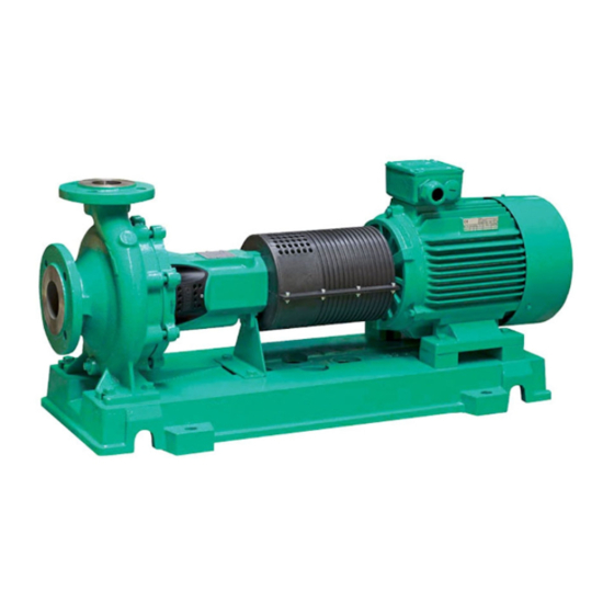
Herunterladen Inhalt Inhalt Diese Seite drucken

Werbung

Verfügbare Sprachen
  • DE

Verfügbare Sprachen

  • DEUTSCH, seite 1
Wilo-NL
D
Einbau- und Betriebsanleitung
GB
Installation and operating instructions
F
Notice de montage et de mise en service
I
Istruzioni di montaggio, uso e manutenzione
E
Instrucciones de instalación y funcionamiento
NL
Inbouw- en bedieningsvoorschriften
P
Manual de instalação e funcionamento
S
Monterings- och skötselinstruktioner
DK
Monterings- og driftsvejledning
CZ
Návod k montáži a obsluze
RUS Инструкция по монтажу и эксплуатации

Werbung

Inhaltsverzeichnis
loading

Inhaltszusammenfassung für Wilo Wilo-NL 32-125

  • Seite 1 Wilo-NL Einbau- und Betriebsanleitung Manual de instalação e funcionamento Installation and operating instructions Monterings- och skötselinstruktioner Notice de montage et de mise en service Monterings- og driftsvejledning Istruzioni di montaggio, uso e manutenzione Návod k montáži a obsluze RUS Инструкция по монтажу и эксплуатации...
  • Seite 3 Einbau- und Betriebsanleitung Installation and operating instructions Notice de montage et de mise en service Istruzioni di montaggio, uso e manutenzione Instrucciones de instalación y funcionamiento Inbouw- en bedieningsvoorschriften Manual de instalação e funcionamento Monterings- och skötselinstruktioner Monterings- og driftsvejledning Návod k montáži a obsluze Инструкция...
  • Seite 4 WILO AG 09/2007...
  • Seite 5 όπως τροποποιήθηκε 91/263/EWG 92/31/EWG, Alçak gerilim direktifi 73/23/EWG ve takip eden, 93/68/EWG 93/68/EWG Οδηγία χα ηλής τάσης EG–73/23/EWG όπως τροποποιήθηκε 93/68/EWG Kısmen kullanılan standartlar: Εναρ ονισ ένα χρησι οποιού ενα πρότυπα, ιδιαίτερα: WILO AG Nortkirchenstraße 100 Erwin Prieß 44263 Dortmund Quality Manager...
  • Seite 6 WILO AG 09/2007...
  • Seite 7 Das Personal für die Montage muss die entspre- siehe die Abschnitte "Inbetriebnahme". chende Qualifikation für diese Arbeiten aufweisen. 2.6 Eigenmächtiger Umbau und 2.3 Gefahren bei Nichtbeachtung der Ersatzteilherstellung Sicherheitshinweise Veränderungen der Pumpe/Anlage sind nur nach Die Nichtbeachtung der Sicherheitshinweise Absprache mit dem Hersteller zulässig. WILO AG 09/2007...
  • Seite 8: Transport Und Zwischenlagerung

    Feststoffe mit einer Größe von bis zu 3 mm kön- VORSICHT! Diese Pumpe darf nur unter den vom nen gefördert werden, dies reduziert jedoch die Käufer angegebenen und von Wilo bestätigten Lebensdauer der Pumpe. Betriebsverhältnissen betrieben werden. Die Garantiebedingungen werden in den allgemei- 4.3 Beschreibung...
  • Seite 9: Vorbereitung Der Installation

    Die Einstellung der Förderleistung erfolgt durch den Absperrschieber, der am Druckstutzen der 5.1.1 Saugleitungen Pumpe montiert wird. Es sollte ein langsam In den Diagrammen befindet sich eine optimale schließender Rückflussverhinderer verwendet Anordnung der Rohrleitungen. werden, um Wasserschläge zu vermeiden. WILO AG 09/2007...
  • Seite 10: Lieferung, Handhabung Und Lagerung

    Leckagen beim Druckaufbau zu verhin- dern, die zu Risiken für Personen führen können. • Sicherstellen, dass die Absperrventile Saugleitung, der Druckleitung und eventuell des Abb. 4a Druckaufbaus gut geschlossen sind. Nur Pumpe • Sicherstellen, dass keine Spannung anliegt. WILO AG 09/2007...
  • Seite 11 In jedem Fall müssen die Anweisungen des Zweifelsfall schwingungshemmende Motorlieferanten befolgt werden, der Motor wird Kontaktstücke verwenden. im Allgemeinen von Wilo in das Aggregat/die Das Aggregat muss korrekt auf seinen Pumpe eingebaut. Fundamenten installiert werden. Um eventuelle Verwindungen zwischen dem Sockel oder dem 7.4 Ausrichtung des Aggregats...
  • Seite 12: In- Und Außerbetriebnahme

    Produkt heiß ist, muss sichergestellt wer- • Der Nenndruck wird im Kapitel "Daten" definiert. den, dass die Flüssigkeit nicht entweichen kann. • Für die Prüfungen kann Wasser verwendet werden. Es kann auch Dampf entweichen, wenn die WILO AG 09/2007...
  • Seite 13 • Wenn der Motor seine Drehzahl erreicht, den Betriebspunkt mithilfe des Absperrschiebers an Leckage möglich. Wenn die Pumpe mit einer externen Spülung, einem Quench oder einem der Druckleitung einstellen (Betriebspunkt: siehe Erhitzungssystem ausgestattet ist, müssen die Datenblatt). WILO AG 09/2007...
  • Seite 14: Wartung, Instandhaltung

    Personal durchgeführt werden. 9.3 Sicherheitshinweise WARNUNG! Wenn die Pumpe explosive, schädliche oder kris- tallisierende Produkte gefördert hat, müssen alle erforderlichen Maßnahmen getroffen werden, um Schäden an Personen und Umwelt zu vermeiden. Der Arbeitsplatz für die Demontage oder die WILO AG 09/2007...
  • Seite 15: Störungen, Ursachen Und Beseitigung

    Stromverlustes wie z.B. beschädigte Kabel oder Flüssigkeitsleckagen auf den elektrischen Teilen überprüfen. Der zulässige Betriebspunkt wird nicht Die im Datenblatt definierten eingehalten. Betriebsbedingungen müssen eingehal- ten werden. Freie oder in der Pumpe festgeklemmte Pumpe öffnen und reinigen. Teile. WILO AG 09/2007...
  • Seite 16: Technische Daten

    Baumaterial der Pumpe und Dichtigkeit Siehe Kapitel 4. Schwingungen Die NL-Pumpen entsprechen den Normen VDI 2056 und ISO 5199 Klasse K für die Pumpen bis 15 kW Antriebsleistung und Klasse M für die Antriebsleitungen über 15 kW. WILO AG 09/2007...
  • Seite 17 100-160 bis 100-250 0,5 Q < Q < 1,1 Q 125-200 bis 125-250 150-200 Diese Betriebsbereiche gelten für wasserähnliche Flüssigkeiten. Wenn Flüssigkeiten mit anderen physischen Eigenschaften transportiert werden, kann es erforderlich sein, die angezeigten Bereiche zu korrigieren. WILO AG 09/2007...
  • Seite 18 G 1/4 15.65 80-160 80-200 80-250 80-315 80-400 G 1/4 100-160 100-200 G 3/8 G 1/8 100-250 100-315 100-400 G 1/4 125-200 G 1/8 125-250 125-315 G 1/4 125-400 150-200 G 1/8 150-250 150-315 G 1/4 150-400 WILO AG 09/2007...
  • Seite 19 150 200 160 530 315 450 100 18 200 150 550 450 M20 M12 370 140 42 110 1) Pumpen Messlehren Transnorm, nicht enthalten in DIN 24255 / EN 733. Gemäß ANSI 150 angebohrte Flansche auf Anfrage. *Anbohrung für Stangen der angegebenen Abmessung. WILO AG 09/2007...
  • Seite 20 93.01 Unterlegscheibe 52.30 * Wellenschutzhülse 93.21 * Sicherungsring 52.40 * Wellenschutzhülse 94.00 * Passfeder für Kupplung 55.40 94.01 * Unterlegscheibe Passfeder für Laufrad 56.00 Gewindestift für Verschleißring 94.02 * Passfeder 56.10 Zapfen 99.99 Plastik-Stopfen • Empfohlenes Verschleißteil WILO AG 09/2007...
  • Seite 21 Deutsch NL 32-125 bis 150-400 Gleitringdichtung NL 32-125 bis 150-400 Stopfbuchse WILO AG 09/2007...
  • Seite 22 WILO AG 09/2007...
  • Seite 23 All values must neither exceed nor fall below the for damages. limit values given in the catalogue or data sheet. In particular, failure to comply with these safety instructions could give rise, for example, to the WILO AG 09/2007...
  • Seite 24: Transport And Storage

    Guarantee is assumed Impurities up to a grain size of 3 mm can be within the scope of the Wilo conditions of sale. handled, but it will shorten the service life. Appropriate application and operating conditions are contained in the attached data sheets 4.1 Safety instruction...
  • Seite 25: Planning The Installation

    3 Suction line 5.1.1 Suction line 4 Bend See the sketches below for the optimum layout 5 Foot valve with strainer of pump installation for flow and suction lift 6 Isolating valve operation. 7 Regulating valve Fig. 3 WILO AG 09/2007...
  • Seite 26 WARNING! Electrical connections must be made according to the European Regulations and Directives for the Standards in Industry and in compliance with the instructions of the local power supply utili- ties of the country concerned. WILO AG 09/2007...
  • Seite 27 In any event, the operating instructions of the 7.2.1 Assembly tools motor manufacturer must be followed, since the Special tools are not required for assembly and motor is generally incorporated by Wilo into the installation. pump set. 7.2.2 Permissible ambient conditions 7.4 Levelling the pumpset...
  • Seite 28 The nominal pump pressure is indicated in the • Use pliers. technical data sheet. • Never touch the parts of the pump that can be hot. • At the end of the purge, close tight the air vent. WILO AG 09/2007...
  • Seite 29 Pumping against a closed valve in the discharge line is permitted only if a minimum output via a WILO AG 09/2007...
  • Seite 30 - Check every week the leak-flow of the gland packing. - Please, refer to the motor instruction manual to be informed about the maintenance planning recommended by the manufacturer of this equipment. (Items to be checked, ball bearing lubrication schedule, and so on). WILO AG 09/2007...
  • Seite 31: Problems, Causes And Remedies

    Operating conditions outside of perfor- Refer to pump operating conditions sta- mance range of pump ted in technical data Loose or jammed parts in the pump Open and clean the pump WILO AG 09/2007...
  • Seite 32: Technical Data

    See chapter 4. Vibrations NL range pumps comply with VDI 2056 and ISO 5199 Class K for pumps with a driving power of up to 15 kW and Class M with a driving power of more than 15 kW. WILO AG 09/2007...
  • Seite 33 < Q < 1,1 Q 125-200 to 125-250 150-200 These operation ranges are given for a fluid similar to water. If the physical properties of the fluid handled are different it might be necessary to amend the data mentioned above. WILO AG 09/2007...
  • Seite 34 G 1/4 15.65 80-160 80-200 80-250 80-315 80-400 G 1/4 100-160 100-200 G 3/8 G 1/8 100-250 100-315 100-400 G 1/4 125-200 G 1/8 125-250 125-315 G 1/4 125-400 150-200 G 1/8 150-250 150-315 G 1/4 150-400 WILO AG 09/2007...
  • Seite 35 450 100 18 200 150 550 450 M20 M12 370 140 1) Transnorm pump sizes, not included in DIN 24255 / EN 733. Flanges drilled according to ANSI 150 on request. *Holes for bolts of the dimensions indicated. WILO AG 09/2007...
  • Seite 36 93.21 * Shaft sleeve Circlip 52.40 * Shaft sleeve 94.00 * Coupling key 55.40 Washer 94.01 * Impeller key 56.00 Grub screw for wear ring 94.02 * 56.10 99.99 Plastic plug • Recommended spare part for maintenance WILO AG 09/2007...
  • Seite 37 English NL 32-125 to 150-400 Mechanical seal NL 32-125 to 150-400 Stuffing box WILO AG 09/2007...
  • Seite 38 WILO AG 09/2007...
  • Seite 39 2.6 Modification du matériel et utilisation de 2.3 Dangers encourus en cas de non-observation pièces détachées non agréées des consignes Toute modification de la pompe ou de La non-observation des consignes de sécurité l'installation ne peut être effectuée que moyen- WILO AG 09/2007...
  • Seite 40: Transport Et Stockage

    L'utilisation d'autres pièces dégage la société Wilo de toute responsabilité. Consignes de sécurité ATTENTION ! Ne pas toucher la pompe en tem- Modes d'utilisation non autorisés pérature.
  • Seite 41: Préparation De L'installation

    Se reporter aux schémas pour une disposition Le réglage du débit sera réalisé par la vanne pla- optimale des tuyauteries. cée au refoulement de la pompe. Le clapet anti- retour sera d’un type à fermeture lente, ceci afin d’éviter les coups de bélier. WILO AG 09/2007...
  • Seite 42 • S’assurer de la bonne fermeture des vannes d’aspiration, de refoulement et éventuellement de pressurisation. Fig. 4a Pompe seule • S’assurer de l’absence de tension sur tous les WILO AG 09/2007...
  • Seite 43 7.2.3 Base, fondation du moteur doivent être respectées, le moteur est La pompe ou le groupe électro-pompe doit être généralement incorporé par Wilo dans le groupe / installé sur un sol plat et non soumis à des vibra- pompe. tions extérieures. En cas de doute, utiliser des plots antivibratiles.
  • Seite 44 Si la pompe est dégazée lorsque le produit • De l’eau peut être utilisée pour les tests. pompé est chaud, faire attention à ce que le liquide ne puisse s’échapper. De la vapeur peut aussi s’échapper si le dégazage est important ou WILO AG 09/2007...
  • Seite 45 à l’aide de la vanne de réchauffage, le flushing, le quench ou le système refoulement (cf. point de fonctionnement : voir de réchauffage doivent être opérationnels avant fiche technique). WILO AG 09/2007...
  • Seite 46: Entretien & Maintenance

    éviter tout danger à l’égard des personnes et de l’environnement. Le poste de travail pour le démontage ou le montage doit être propre. La pompe pouvant encore contenir du fluide WILO AG 09/2007...
  • Seite 47: Pannes, Causes Et Remèdes

    électri- Le point de fonctionnement admissible Respecter les conditions de fonctionne- n’est pas respecté ment définies dans la fiche technique Pièces libres ou coincées dans la pompe Ouvrir et nettoyez la pompe WILO AG 09/2007...
  • Seite 48: Données Techniques

    Voir chapitre 4. Vibrations Les pompes NL répondent aux normes VDI 2056 et ISO 5199 Classe K pour les pompes jusqu’à 15 kW de puissance d’entraînement et Classe M pour les puissances d’entraînement supérieures à 15 kW. WILO AG 09/2007...
  • Seite 49 < Q < 1,1 Q 125-200 à 125-250 150-200 Ces plages de fonctionnement sont applicables pour des liquides similaires à l’eau. Si des liquides aux propriétés physiques différentes sont véhiculés, il peut être nécessaire de corriger en conséquences les plages annoncées. WILO AG 09/2007...
  • Seite 50 G 1/4 15.65 80-160 80-200 80-250 80-315 80-400 G 1/4 100-160 100-200 G 3/8 G 1/8 100-250 100-315 100-400 G 1/4 125-200 G 1/8 125-250 125-315 G 1/4 125-400 150-200 G 1/8 150-250 150-315 G 1/4 150-400 WILO AG 09/2007...
  • Seite 51 450 100 18 200 150 550 450 M20 M12 370 140 1) Calibres pompes Transnorm, non compris dans DIN 24255 / EN 733. Brides percées suivant ANSI 150 sur demande. *Perçage pour tiges de la dimension indiquée. WILO AG 09/2007...
  • Seite 52 52.40 * Chemise d‘arbre PE 94.00 * Clavette d‘entraînement accoupl. 55.40 94.01 * Rondelle Clavette d‘entraînement roue 56.00 Vis sans tête (bague d‘usure) 94.02 * Clavette d‘entraînement 56.10 Pion d’arrêt 99.99 Bouchon raccordement externe • Pièce d’usure recommandée WILO AG 09/2007...
  • Seite 53 Français NL 32-125 à 150-400 Garniture mécanique NL 32-125 à 150-400 Presse-étoupe WILO AG 09/2007...
  • Seite 54 WILO AG 09/2007...
  • Seite 55 Qualsiasi modifica alla pompa o all'impianto deve 2.3 Pericoli conseguenti al mancato rispetto delle essere preventivamente concordata e autorizzata prescrizioni di sicurezza dal produttore. I pezzi di ricambio originali e gli WILO AG 09/2007...
  • Seite 56: Trasporto E Magazzinaggio

    È possibile pompare solidi con grandezza fino a 3 ATTENZIONE! Questa pompa deve funzionare solo mm, ma ciò riduce la vita operativa della pompa. nelle condizioni di esercizio specificate dall'acquirente e confermate da WILO. 4.3 Descrizione Le condizioni di garanzia sono definite nelle Configurazione...
  • Seite 57: Operazioni Preliminari All'installazione

    5.1.1 Tubazioni di aspirazione bocchettone di mandata della pompa. Occorre I diagrammi riportano la disposizione ottimale utilizzare una valvola di non ritorno a chiusura delle tubazioni. lenta per evitare colpi d'ariete. WILO AG 09/2007...
  • Seite 58: Installazione

    • Accertarsi che le valvole di arresto della tubazione di aspirazione e della tubazione di mandata siano Fig. 4a ben chiuse. Solo pompa • Accertare l'assenza di tensione. WILO AG 09/2007...
  • Seite 59 In caso di montato da WILO nel complessivo/nella pompa. dubbio utilizzare elementi di contatto antivibranti. 7.4 Allineamento del complessivo È...
  • Seite 60 Quando la pompa viene sfiatata, se il prodotto • Per i controlli è possibile utilizzare acqua. pompato è caldo occorre accertarsi che il liquido non possa fuoriuscire. Il vapore può fuoriuscire anche quando lo sfiato è notevole oppure viene WILO AG 09/2007...
  • Seite 61 Se la pompa è dotata di valvola d'intercettazione sul tubo di mandata un lavaggio esterno, un raffreddamento o un sistema di riscaldamento, questi devono essere (punto di lavoro: vedere la scheda dati). WILO AG 09/2007...
  • Seite 62 9.3 Prescrizioni di sicurezza AVVISO! Se la pompa ha eseguito il pompaggio di prodotti esplosivi, nocivi o cristallizzanti, devono essere intraprese tutte le necessarie misure onde evitare danni alle persone e all'ambiente. WILO AG 09/2007...
  • Seite 63: Guasti, Cause E Rimedi

    Il punto di lavoro consentito non viene Devono essere rispettate le condizioni di rispettato. esercizio definite nella scheda dati. Componenti non fissati oppure bloccati Aprire la pompa e procedere alla pulitura. nella pompa. WILO AG 09/2007...
  • Seite 64: Dati Tecnici

    Materiale di fabbricazione della pompa e della tenuta Vedere capitolo 4. Vibrazioni Le pompe NL sono conformi alle norme VDI 2056 e ISO 5199 Classe K sulle pompe con potenza motrice fino a 15 kW e Classe M sulle WILO AG 09/2007...
  • Seite 65 < Q < 1,1 Q da 125-200 a 125-250 150-200 Questi campi di funzionamento sono validi per liquidi tipo acqua. In caso di convogliamento di liquidi con altre proprietà fisiche, potrebbe essere necessario correggere i campi indicati. WILO AG 09/2007...
  • Seite 66 G 1/4 15.65 80-160 80-200 80-250 80-315 80-400 G 1/4 100-160 100-200 G 3/8 G 1/8 100-250 100-315 100-400 G 1/4 125-200 G 1/8 125-250 125-315 G 1/4 125-400 150-200 G 1/8 150-250 150-315 G 1/4 150-400 WILO AG 09/2007...
  • Seite 67 18 200 150 550 450 M20 M12 370 140 42 110 1) Calibri delle pompe secondo Transnorm, non riportate nella norma DIN 24255 / EN 733. Flangia forata secondo ANSI 150 su richiesta. *Foratura per aste della misura prescritta. WILO AG 09/2007...
  • Seite 68 Bussola di protezione albero 94.00 * Chiavetta per giunto 55.40 Rondella di spessore 94.01 * Chiavetta per girante 56.00 Prigioniero per anello di usura 94.02 * Chiavetta 56.10 Perno 99.99 Tappo di plastica • Parte di usura consigliata WILO AG 09/2007...
  • Seite 69 Italiano NL da 32-125 a 150-400 Tenuta meccanica NL da 32-125 a 150-400 WILO AG 09/2007...
  • Seite 70 WILO AG 09/2007...
  • Seite 71 Las modificaciones en la bomba o la instalación 2.3 Peligro por no seguir las instrucciones de sólo deben realizarse con la previa autorización del seguridad fabricante. La utilización de repuestos originales y La inobservancia de las instrucciones de de accesorios autorizados por el fabricante WILO AG 09/2007...
  • Seite 72: Transporte Y Almacenamiento

    ¡ATENCIÓN! Esta bomba sólo debe ponerse en bombeadas pero esto reduce la vida útil de la marcha bajo las condiciones de servicio indicadas bomba. por el comprador y confirmadas por Wilo. Las condiciones de la garantía están definidas en 4.3 Descripción Construcción...
  • Seite 73: Preparación De La Instalación

    5.1.1 Tuberías de aspiración impulsión de la bomba. Debe utilizarse una En los diagramas se muestra una colocación válvula antirretorno de cierre lento para evitar óptima de las tuberías. golpes de ariete. WILO AG 09/2007...
  • Seite 74: Instalación

    7.1 Instrucciones de seguridad Retirar los dispositivos de cierre de las bridas de la bomba inmediatamente antes de conectar las tuberías. rectamente conectadas para evitar que se produzcan fugas Fig. 4a Solo bomba durante el aumento de presión. Estas fugas WILO AG 09/2007...
  • Seite 75 En cualquier caso deben seguirse las más baja posible. instrucciones del proveedor del motor. Generalmente el motor está montado por Wilo en 7.2.3 Base, cimiento el grupo / la bomba. La bomba o el grupo debe instalarse sobre una base plana y no debe estar expuesta a vibraciones externas.
  • Seite 76: Puesta En Marcha Y Puesta Fuera De Servicio

    De este modo se evita una mar INDICACIÓN: Cuando se r de la bomba, la pr superar en 1 a 3 v nominal de la bomba. ¡ADVERTENCIA! Al purgar la bomba, si el pr "Datos". puede pr WILO AG 09/2007...
  • Seite 77 En la primera puesta en marcha puede producirse revoluciones, ajustar el punto de funcionamiento mediante la llave de corte de la tubería de impulsión (punto de funcionamiento: véase la ficha técnica). un dispositivo externo de enjuague, uno de WILO AG 09/2007...
  • Seite 78: Tareas De Mantenimiento

    Sólo personal autorizado puede realizar trabajos en la red eléctrica. 9.3 Instrucciones de seguridad ¡ADVERTENCIA! Cuando la bomba ha impulsado productos explosivos, nocivos o cristalizantes, deben tomarse todas las medidas necesarias para evitar daños personales o del medio ambiente. WILO AG 09/2007...
  • Seite 79: Averías, Causas Y Solución

    No se respeta el punto de Deben cumplirse las condiciones de funcionamiento admitido. funcionamiento descritas en la ficha técnica. Piezas sueltas o atascadas en la máquina. Abrir y limpiar la bomba. WILO AG 09/2007...
  • Seite 80: Datos Técnicos

    Las bombas NL cumplen con las normativas VDI 2056 e ISO 5199 clase K para las bombas con hasta 15 kW de potencia de accionamiento y clase M para las potencias de accionamiento superiores a 15 kW. WILO AG 09/2007...
  • Seite 81 0,5 Q < Q < 1,1 Q 125-200 a 125-250 150-200 Estos intervalos de funcionamiento son aplicables para líquidos similares al agua. Si se transportan líquidos con otras propiedades físicas, puede ser necesario corregir los intervalos indicados. WILO AG 09/2007...
  • Seite 82 G 1/4 15.65 80-160 80-200 80-250 80-315 80-400 G 1/4 100-160 100-200 G 3/8 G 1/8 100-250 100-315 100-400 G 1/4 125-200 G 1/8 125-250 125-315 G 1/4 125-400 150-200 G 1/8 150-250 150-315 G 1/4 150-400 WILO AG 09/2007...
  • Seite 83 550 450 M20 M12 370 140 42 110 45 12 1) Tamaño de las bombas Transnorm, no contenidos en DIN 24255 / EN 733. conforme a ANSI 150 bridas perforadas a petición. *Perforación para barras de las dimensiones indicadas. WILO AG 09/2007...
  • Seite 84 Arandela Camisa del eje Anillo de fijación Camisa del eje veta paralela para acoplamiento 55.40 Arandela 56.00 Varilla roscada para el anillo de veta paralela para rodete desgaste veta paralela 56.10 Espiga 99.99 Tapón de plástico recomendada WILO AG 09/2007...
  • Seite 85 Español NL 32-125 a 150-400 Junta mecánica NL 32-125 a 150-400 Prensaestopas WILO AG 09/2007...

Inhaltsverzeichnis