Herunterladen Inhalt Inhalt Diese Seite drucken
IKA RV 10 series Betriebsanleitung

IKA RV 10 series Betriebsanleitung

Rotationsverdampfer
Vorschau ausblenden Andere Handbücher für RV 10 series:
Inhaltsverzeichnis

Werbung

Verfügbare Sprachen
  • DE

Verfügbare Sprachen

  • DEUTSCH, seite 4
20000009249
RV 10 control_RV 10 auto_052018
Betriebsanleitung
Operating instructions
Mode d'emploi
Instrucciones de manejo
Instruzioni per l'uso
IKA
DE
4
Руководство по эксплуатации RU
EN
32
Instruções de serviço
FR
60
Instrucja obsługi
ES
88
Çalışma talimatları
IT
116
RV 10 control
®
IKA
RV 10 auto
®
144
PT
172
PL
200
TR
228

Werbung

Inhaltsverzeichnis
loading

Inhaltszusammenfassung für IKA RV 10 series

  • Seite 1 20000009249 RV 10 control_RV 10 auto_052018 RV 10 control ® RV 10 auto ® Betriebsanleitung Руководство по эксплуатации RU Operating instructions Instruções de serviço Mode d‘emploi Instrucja obsługi Instrucciones de manejo Çalışma talimatları Instruzioni per l’uso...
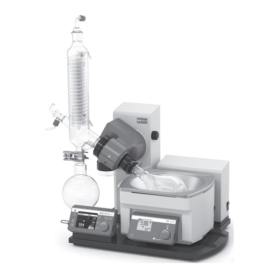
  • Seite 2: Device Setup

    Geräteaufbau - Device setup Geräteaufbau - Device setup HB 10.2 Schermo di protezione (non compreso nella dotazione di fornitura) HB 10.1 Calotta di protezione (non compresa nella dotazione di fornitura) Bagno termostatico HB 10 Gruppo motore RV 10 auto Set di vetreria Supporto Flacone condensato Защитный...
  • Seite 3 Netzschalter "Power" switch Interrupteur Interruptor de Taste „Power" "Power" key Touche « Marche » alimentación Taste Liftposition „" Lift position "" key Touche de levage «  » Tecla “Power” Taste Liftposition „" Lift position "" key Touche de levage «  » (Alimentación) Drehzahltaste “Rotating speed”...
  • Seite 4: Eu-Konformitätserklärung

    2011/65/EU und mit den folgenden Normen und normativen Dokumenten übereinstimmt: EN 61010-1, EN 61010-2-051, EN 61326-1, EN 60529 und EN ISO 12100. Eine Kopie der vollständigen EU-Konformitätserklärung kann bei sales@ika.com angefordert werden. Zeichenerklärung (Extrem) Gefährliche Situation, bei der die Nichtbeachtung des Sicherheitshinweises zu Tod oder schwerer GEFAHR Verletzung führen kann.
  • Seite 5: Sicherheitshinweise

    Sicherheitshinweise Zu Ihrem Schutz • Beachten Sie die Betriebsanleitung des Zubehörs z.B. • Lesen Sie die Betriebsanleitung vor Inbetriebnahme vollständig Vakuumpumpe, Heizbades. und beachten Sie die Sicherheitshinweise. • Verlegen Sie den druckseitigen Ausgang der Vakuumpumpe in • Bewahren Sie die Betriebsanleitung für Alle zugänglich auf. den Laborabzug.
  • Seite 6: Bestimmungsgemäßer Gebrauch

    Drehzahlen. Große Unwuchtskräfte führen zum Bruch des Dampdurchführungsrohres! Bestimmungsgemäßer Gebrauch • Verwendung Das Gerät ist für den Gebrauch in allen Bereichen geeignet, außer: Das Gerät ist in Verbindung mit dem von IKA - Wohnbereichen, ® empfohlenen - Bereichen, die direkt an ein Niederspannungs-Versorgungsnetz Zubehör geeignet für:...
  • Seite 7: Auspacken

    Auspacken • Auspacken - Packen Sie das Gerät vorsichtig aus, - Nehmen Sie bei Beschädigungen sofort den Tatbestand auf (Post, Bahn oder Spedition). • Lieferumfang         RV 10 control V x x x x x x x x x x x x ...
  • Seite 8 Bedingt durch die minimale zeitliche Differenz von dem Zeitpunkt wird nicht benötigt und darf nicht angeschlossen werden! Schlie- ab Detektion des Druckwertes, Sollwertabgleich zum Schalten ßen Sie dafür die Vakuumpumpe (z.B. IKA Vacstar digital Pumpe) ® eines Vakuumventiles, sowie der Saugleistung des vakuumerzeu- an der rückseitigen Schnittstelle an den Rotationsverdampfer an.
  • Seite 9: Aufstellung

    Aufstellung Antrieb RV 10 auto Transportsicherung lösen! Setzen Sie die Flasche ein und montieren Sie die mitgelieferten Schlauchanschlüsse an die Flasche VORSICHT Stellen Sie den Antrieb auf einen Winkel von ca. 30° • Halten Sie den Lift mit der Hand auf der Höhenposition und •...
  • Seite 10 Heizbad Beachten Sie die Betriebsanleitung des VORSICHT Heizbades, Kapitel „Inbetriebnahme”! • Stellen Sie das Heizbad auf die Stellfläche des Rotationsantriebes und schieben sie es in die linke Position Hinweis: Der Datenaustausch zwischen Antriebseinheit und Heiz- bad findet mittels einer Infrarot- Schnittstelle (1) statt. Beachten Sie, dass die Kommunikation nur bei freier, nicht unterbrochener Lichtstrecke gewährleistet ist! Glassatz...
  • Seite 11 Erstinbetriebnahme • Dampfdurchführungsrohr einsetzen (1). • Dichtung einsetzen (2). Beachten Sie die Lage der Dichtung! • Überwurfmutter (3b) über den Flansch des Kühlers (3a) schie- ben. • Ringfeder (3c) ebenfalls über den Flansch des Kühlers (3a) schieben. • Kühlers (3a) auf die Dichtung (2) aufsetzen. •...
  • Seite 12 Montage Glassatz Hinweis: Beachten Sie die „Zeichnungen für die Montage des Glassatzes“ auf Seite 284. Pos. Bezeichnung Menge RV 10.1 RV 10.2 RV 10.3 RV 10.4 RV 10.5 RV 10.6 unbeschichtet unbeschichtet unbeschichtet unbeschichtet unbeschichtet unbeschichtet RV 10.10 beschichtet RV 10.20 beschichtet RV 10.30 beschichtet RV 10.40 beschichtet RV 10.50 beschichtet...
  • Seite 13 Verschlauchung RV 10.5001 Wasserventil RV 10.4002 Schlauchschelle Schlauchschelle Silikonschlauch optional) Vakuummagnetventil für Silikonschläuche für Vakuumschlauch (Innendurchm. 5 mm) Pos. 5, 6 & 7 Pos. 8 für Wasser Silikonschlauch (Innendurchm. 6 mm) Silikonschlauch (Innendurchm. 7 mm) Vakuumschlauch Verbindungsstück für Wasser für Wasser für Wasserventil RV 10.3_30 RV 10.5_50...
  • Seite 14 Wasser • Lösen Sie die Schlauchverbindung mit dem im Lieferumfang ent- • Schließen Sie den Wasserzulauf an Ihre Wasserversorgung haltenen Griff. an (mit optionalem Drosselventil Wasser RV 10.5001). Be- achten Sie die technischen Daten zur Wasserversorgung. Das Drosselventil Wasser RV 10.5001 ist nicht geeignet für den Betrieb am Kühlaggregat, da der Durchfluss zu stark reduziert wird.
  • Seite 15: Arbeitsbildschirm Im Auslieferzustand

    Inbetriebnahme Arbeitsbildschirm im Auslieferzustand Nach dem Einschalten des Gerätes er- Danach wird automatisch im Display der Arbeitsbildschirm einge- scheint für einige Sekunden der Startbild- blendet. schirm. Es werden der Gerätename und die Software-Versionen angezeigt. Anschließend wird eine Information zum Download des Firmware Update Tools eingeblendet.
  • Seite 16: Menüstruktur

    Menüstruktur Werkseinstellung Verdampfer Modi Automatisch Heizbadmedium............Wasser Standardtemperatur............. 60 °C Manuell...................... 1013 mbar Pumpe %....................50% Volumen Lösemittel..............Acetic acid Ziel................100 ml Effizienz............... 80% Justierung..............- Programm....................- Lösemittel..............Acetic acid 100% Trocknenlauf............... - Starte nach... mm:ss............... 30:00 Reinigung Dauer mm:ss...............
  • Seite 17 Werkseinstellung Weitere Durchflussregelung...................  Einstellungen Heizbadmedium..................Wasser Kühlerleistungsgrenze................900 w Max. Kühlerleistung................0 w Wert..........00:10 Intervall Rotation Intervallmodus Wert........00:10 Aktivieren..................- Grenzwerte Minimum..................5 rpm Maximum..................300 rpm Timerfunktion Timer Zeit hh:mm:ss............00:00:00 Signalton nach Ablauf..............- Aktivieren..................- Anzeige.............................
  • Seite 18 Werkseinstellung Service Belüftungsventil............- Ventile Vakuumventil............- Wasserventil............. - Pumpe......................... - Temperatureinstellung....................- Einstellungen Languages English................ Deutsch................- Français................- Español................- Italiano................- Português................. - Pусский язык..............- 中文................- 한국어................- 日本語................- Druck Einheiten mbar........ hPa..........
  • Seite 19 Menü (Details) 1. Verdampfer Reinigung Modi Starte nach...: Stellen Sie die Mindestzeit ein, die eine Messung Automatisch: In diesem Modus erkennt das System die tatsächli- laufen soll, bevor die Reinigung nach der Messung aktiviert wird. che Verdampfung durch Überprüfen der Temperaturdifferenz zwi- Der Reinigungsvorgang beginnt, wenn die Messung mindestens schen Wassereinlauf und -ablauf.
  • Seite 20 Hier kann man das zu destillierende Löse- Aktionen nach der Destillation mittel und seine Parameter (Bezeichnung, Formel, Heizbadtemperatur, Rotationsge- schw., Siedepunkt, Effizienz, Wärmeka- pazität, Entalpy, Dichte und i-Faktor) aus der Bibliothek auswählen. Die Temperatur, die effizienz und die Rotationsdrehzahl des Verdampferbads kann eingestellt werden.
  • Seite 21 4. Display In diesem Menü kann der Benutzer festlegen, welche Informa- tionen (Timer, Durchfluss, ΔT und/oder Kühlerleistung) auf dem Hauptbildschirm erscheinen sollen. 5. Programme Letzte Messung Speichern als: Speichern des Destillationsverlaufs als Programm. Bearb.: Zum Bearbeiten der gewählten Programmparameter. Mit dem Start-Stopp-Knopf auf „bearb.“ drücken, um mit der Be- arbeitung der ausgewählten Programmparameter zu beginnen.
  • Seite 22 Drehzahl bear- beiten Zeit bearbeiten Beispiel zur Speicherung der letzte Messung 6. Sicherheit Passworts ist es auf 0 0 0 zu setzen. Fortfahren nach Stromausfall Wenn diese Option aktiviert ist, wird die Messung nach einer Stromunterbrechung fortgeführt. Diese Option ist nur im Auto- matischen, 100 % oder Volumenmodus wählbar.
  • Seite 23: Aufstellung Heizbad

    Aufstellung Heizbad Hinweis: Vermeiden Sie Wellenbildung. Beachten Sie auch die Betriebsanlei- VORSICHT • Schalten Sie das Heizbad am Hauptschalter ein. tung des Heizbades IKA ® HB 10! Hinweis: Vermeiden Sie Spannungen am Glas durch unterschied- liche Verdampferkolben- und Heizbadtemperatur beim Absenken •...
  • Seite 24: Schnittstellen Und Ausgänge

    Erfassung der Gerätedaten, das auch grafische Eingaben von tax und Befehle des virtuellen COMPorts sind wie unter RS 232 z.B. Drehzahlrampen erlaubt. Schnittstelle beschrieben. Nachfolgend sehen Sie eine Übersicht der von den IKA Control- ® Geräten verstandenen (NAMUR)-Befehlen. Verwendete Abkürzungen:...
  • Seite 25: Wartung Und Reinigung

    Tensidhaltiges Wasser Hinweis: Für Glassätze kontaktieren Sie bitte Ihren lokalen Brennstoffe Tensidhaltiges Wasser Händler; schicken Sie Glassätze nicht an unser Werk. Nicht genannte Stoffe Bitte fragen Sie bei IKA nach ® Sicherheitsanhebung Tragen Sie zum Reinigen des Gerätes Schutzhandschuhe. Die Sicherheitsanhebung muss täglich vor dem Betrieb überprüft Elektrische Geräte dürfen zu Reinigungszwecken nicht in das Rein-...
  • Seite 26 RV 10.3 Vertikal-Intensivkühler mit Verteilerstück (1) RV 10.30 Vertikal-Intensivkühler mit Verteilerstück, beschichtet (1) RV 10.4 Trockeneiskühler (2) RV 10.40 Trockeneiskühler, beschichtet (2) RV 10.5 Rückflussdestillation mit Vertikalkühler (o.Abb.) RV 10.50 Rückflussdestillation mit Vertikalkühler, beschichtet (o.Abb.) RV 10.6 Rückflussdestillation mit Intensivkühler (3) RV 10.60 Rückflussdestillation mit Intensivkühler, beschichtet (3) ...
  • Seite 27 RV 10.100 KS 35/20 Auffangkolben 100 ml RV 10.101 KS 35/20 Auffangkolben 250 ml RV 10.102 KS 35/20 Auffangkolben 500 ml RV 10.103 KS 35/20 Auffangkolben 1000 ml RV 10.104 KS 35/20 Auffangkolben 2000 ml RV 10.105 KS 35/20 Auffangkolben 3000 ml RV 10.200 KS 35/20 Auffangkolben, beschichtet 100 ml RV 10.201...
  • Seite 28: Fehlercodes

    RV 10.606 NS 29/32 Destillationsspinne mit 5 Flaschen 50 ml RV 10.607 NS 29/32 Destillationsspinne mit 5 Flaschen 100 ml RV 10.3000 Anbauplatte RV 10.4002 Magnetventil Laborvakuum (1) RV 10.5001 Drosselventil Wasser (2),nur für an Betrieb an Wasserleitung! RV 10.5002 Wasserfilter (3) RV 10.5003 Druckregelventil (4)
  • Seite 29: Innentemperatur Analyse Der Internen Leiterplat

    Fehlermeldung Wirkung Ursache Korrekturmaßnahme System undicht Die Druckgradientenanalyse er- Der Anschluss des Vakuumschlauchs Den Anschluss des Vakuumschlauchs gibt eine Abweichung, aber der ist nicht dicht. prüfen. Sollwert wird nicht erreicht. Der Behälter ist nicht dicht. Den Behälter prüfen. Eingestellter Drucksollwert wird Die Leistung der Vakuumpumpe ist Die technischen Daten der Pumpe nicht erreicht.
  • Seite 30: Gewährleistung

    Die Service-Abteilung kontaktieren. sen oder Schreiben Schreiben Lässt sich der Fehler durch die beschriebenen Maßnahmen nicht beseitigen oder bei einem anderen Fehler: - wenden Sie sich bitte an die IKA ® Serviceabteilung, - senden Sie das Gerät mit einer kurzen Fehlerbeschreibung ein.
  • Seite 31: Technische Daten

    Technische Daten Betriebsspannungsbereich 100...240 ± 10% Nennspannung 100...240 Frequenz 50/60 Anschlussleistung ohne Heizbad Anschlussleistung im Stand by-Betrieb Drehzahl 0/5...300 Drehzahltoleranz ± 1(Sollwert Drehzahl < 100 rpm) ± 1(Sollwert Drehzahl ≥ 100 rpm) Drehzahlanzeige digital Display Abmessung Sichtbereich (B x H) 70 x 52 Anzeige TFT-Anzeige...
  • Seite 32: Inhaltsverzeichnis

    2011/65/EU and conforms with the following standards or normative documents: EN 61010-1, EN 61010-2-051, EN 61326-1, EN 60529 and EN ISO 12100. A copy of the complete EU Declaration of Conformity can be requested at sales@ika.com. Explication of warning symbols Indicates an imminently hazardous situation, which, if not avoided, will result in death, serious injury.
  • Seite 33: Safety Instructions

    Safety instructions For your protection • Refer to the operating instructions for the accessories, e.g. • Read the operating instructions completely before starting up vacuum pump, heating bath. and follow the safety instructions. • Position the positive pressure outlet of the vacuum pump under •...
  • Seite 34: Correct Use

    • Socket must be earthed (protective ground contact). If the safety lift does not work, please contact the IKA ® Service • Removable parts must be refitted to the appliance to prevent department.
  • Seite 35: Unpacking

    Unpacking • Unpacking - Unpack the device carefully. - Any damage should be notified immediately to the shipping agent (post, rail or logistics company). • Scope of delivery         RV 10 control V x x x x x x x x x x x x ...
  • Seite 36: Vacuum Control

    The device will fall slightly short of the target value setting due red and must not be connected! To do so, connect the vacuum to the minimum time difference from detection of the pressure pump (e.g. IKA Vacstar digital pump) to the port on the rear of ®...
  • Seite 37: Setting Up

    Setting up Drive RV 10 auto Loosen transportation lock! Insert the bottle and attach the supplied hose connectors to the bottle CAUTION Set the drive at an angle of approx. 30° • Remove the clamping device for the angle setting of the rota- •...
  • Seite 38: Heating Bath

    Heating bath Refer to the chapter “Commissioning“ CAUTION in the heating bath instruction manual! • Place the heating bath on the stand of the rotation drive and push it into the left position. Note: Data is exchanged between the drive unit and the heating bath by means of an infrared link (1).
  • Seite 39 First use • Insert vapor tube (1). • Insert the vacuum seal (2). Pay attention to the correct positon of the vacuum seal! • Slide the union nut (3b) over the flange on the condenser (3a). • Also slide the annular spring (3c) over the flange on the con- denser (3a).
  • Seite 40 Mounting the glassware Note: Observe "Drawings for mounting the glassware" on page 284. Item Designation Quantity RV 10.1 non-coated RV 10.2 non-coated RV 10.3 non-coated RV 10.4 non-coated RV 10.5 non-coated RV 10.6 non-coated RV 10.10 coated RV 10.20 coated RV 10.30 coated RV 10.40 coated RV 10.50 coated...
  • Seite 41 Hose system RV 10.5001 Water valve RV 10.4002 Vacuum valve Hose clamp Hose clamp Silicon hose (inner dia. 5 mm) Optional) for silicone hose for vacuum hose for water pos. 5, 6 & 7 pos. 8 Silicon hose (inner dia. 6 mm) Silicon hose (inner dia.
  • Seite 42 Water • Release the hose connection using the supplied tool. • Connect the water inlet to the water supply (with op- tional RV 10.5001 water regulator valve). Please re- fer to the technical data relating to the water supply. The RV 10.5001 water regulator valve is not suitable for use on the condenser unit because it would reduce the flow rate too greatly.
  • Seite 43: Commissioning

    The play. device name and the software versions are displayed. An information prompt then appears to download the IKA firmware update tool. ® Explanation of symbols on the working screen The symbols displayed change depending on the status and set- tings of RV 10 auto.
  • Seite 44: Menu Structure

    Menu structure Factory settings Evaporator Modes Automatic Bath medium.............. Water Start temperature............60 °C Manual...................... 1013 mbar Pump %...................... 50% Volume Solvent............... Acetic acid Target................. 100 ml Efficiency..............80% Adjustment..............- Program..................... - Solvent..............Acetic acid 100% Drying................ - Start after... mm:ss...............
  • Seite 45 Factory settings Flow control.....................  Advanced Bath medium................... Water Cooler power limit..................900 w Max power of cooler................0 w Value..........00:10 Interval Rotation Interval mode Value........00:10 Activate................... - Speed limit Minimum..................5 rpm Maximum..................300 rpm Timer function Timer Time hh:mm:ss............
  • Seite 46 Factory settings Service Venting valve............- Valves Vacuum valve............- Water valve.............. - Pump........................... - Temperature adjustment....................- Settings Language English................ Deutsch................- Français................- Español................- Italiano................- Português................. - Pусский язык..............- 中文................- 한국어................- 日本語................- Pressure Units mbar........
  • Seite 47 Menu (details) 1. Evaporator Modes Duration: Set the duration of the cleaning process. Pump speed: The set pump speed in the cleaning menu is used to set the speed of the pump during the cleaning process. Higher speed causes partial vacuum in NOTICE the glassware if the system is closed.
  • Seite 48 Advanced Calculator Flow control: This setting can be deactivated in the manual mode It helps you to calculate the boiling point (vapor temperature) of if dry ice is used instead of a cooler. solvent, heating bath temperature and pressure. If one of the 3 Bath medium: Select either water or oil as the medium for the values has been defined, the other 2 values will be given.
  • Seite 49 5. Program Last measurement Save as: Save the distillation sequence as a program. Edit: Edit the selected program parameters. Start to edit the selected program parameters by pressing on menu option “Edit” with start/stop knob. The user can edit, insert or delete one selected program segment in the program.
  • Seite 50 Example of saving the last measurement 6. Safety Continue after power failure If this option is activated the measurement will continue after a break caused by a power failure. This option is only available in Automatic, 100 % and Volume mode. Activate: If tick is shown the option is activated.
  • Seite 51 Note: Avoid stress on the glass due to different evaporation flask Refer to the operating instructions CAUTION and heating bath temperatures when lowering the evaporation for the heating bath IKA ® HB 10! flask into the heating bath! Note: If non-original accessories are used that are not supplied •...
  • Seite 52: Interfaces And Outputs

    ® face from: http://www.ika.com/ika/lws/download/usb-driver.zip. rotary evaporator and the PC. With a suitable terminal or commu- Install the driver by running the setup file. Then connect the IKA nication program these commands can be transmitted directly to ® device through the USB data cable to the PC. The data commu- the rotary evaporator.
  • Seite 53: Maintenance And Cleaning

    (See the section entitled Safety In- Before using another than the recommended method for cleaning structions - Safety Lift)! If the safety lift is not working, please or decontamination, the user must ascertain with IKA that this ®...
  • Seite 54 RV 10.3 Vertical-intensive condenser with manifold (1) RV 10.30 Vertical-intensive condenser with manifold, coated (1) RV 10.4 Dry ice condenser (2) RV 10.40 Dry ice condenser, coated (2) RV 10.5 Vertical-condenser with manifold and cut-off valve for reflux distillation (no picture) RV 10.50 Vertical-condenser with manifold and cut-off valve for reflux distillation, coated (no picture)
  • Seite 55 RV 10.100 KS 35/20 Receiving flask 100 ml RV 10.101 KS 35/20 Receiving flask 250 ml RV 10.102 KS 35/20 Receiving flask 500 ml RV 10.103 KS 35/20 Receiving flask 1000 ml RV 10.104 KS 35/20 Receiving flask 2000 ml RV 10.105 KS 35/20 Receiving flask 3000 ml RV 10.200...
  • Seite 56 RV 10.606 NS 29/32 Distillation spider with 5 flasks 50 ml RV 10.607 NS 29/32 Distillation spider with 5 flasks 100 ml RV 10.3000 Extension plate RV 10.4002 Solenoid valve (laboratory vacuum system) (1) RV 10.5001 Water regulator valve (2), only for use on water supply line! RV 10.5002 Filter (3) RV 10.5003...
  • Seite 57: Error Messages

    Error messages Any malfunctions during operation will be identified by an error message on the display. Once a serious error message has been displayed, the lift moves to the top end position and the device can no longer be operated. Proceed as follows in such cases: - switch off device using the mains switch, - carry out corrective measures,...
  • Seite 58: Warranty

    ® - send the device for repair, including a short description of the fault. Warranty In accordance with IKA ® warranty conditions, the warranty The warranty does not cover worn out parts, nor does it apply period is 24 months. For claims under the warranty please contact...
  • Seite 59: Technical Data

    Technical Data Operating voltage range 100...240 ± 10% Rated voltage 100...240 Frequency 50/60 Power input without heating bath Power input operation “standby” Speed 0/5...300 Speed tolerance ± 1(Set speed < 100 rpm) ± 1(Set speed ≥ 100 rpm) Speed display digital Dimensions of visible display area (W x H) 70 x 52...
  • Seite 60: Déclaration Ue De Conformité

    2006/42/CE, 2014/30/UE et 2011/65/UE, ainsi qu‘aux normes et documents normatifs suivants: EN 61010-1, EN 61010-2-051, EN 61326-1, EN 60529 et EN ISO 12100. Une copie de la déclaration UE de conformité complète peut être demandée en adressant un courriel à l'adresse sales@ika.com. Explication des symboles Situation (extrêmement) dangereuse dans laquelle le non-respect des consignes de sécurité...
  • Seite 61: Consignes De Sécurité

    Consignes de sécurité Pour votre protection • Respectez le mode d'emploi des accessoires, par ex. de la • Lire entièrement le mode d'emploi avant la mise en service et pompe à vide, du bain chauffant. respecter les consignes de sécurité. •...
  • Seite 62: Utilisation Conforme

    • La prise doit être mise à la terre (contact à conducteur de Si le dispositif de levage de sécurité ne fonctionne pas, veuillez protection). contacter le service après-vente IKA ® • Les pièces démontables de l‘appareil doivent être reposées sur Concernant l‘évaporateur (ballon d‘évaporation plus contenu), le...
  • Seite 63: Déballage

    Déballage • Déballage - Déballer l'appareil avec précaution, - En cas de dommages, établir immédiatement le constat correspondant (poste, chemin de fer ou transporteur). • Contenu de la livraison         RV 10 control V x x x x x x x x x x x x ...
  • Seite 64: Régulation Du Vide

    Une fois la valeur de consigne atteinte, la conduite d'aspiration vanne de vide RV10.4002 n'est pas nécessaire et ne doit pas être est fermée. En raison du délai minimal entre la détection de la raccordée ! Pour cela, raccorder la pompe à vide (p. ex. IKA ® Vacstar valeur de pression et la comparaison avec la valeur théorique pour...
  • Seite 65: Installation

    Installation Entraînement RV 10 auto Desserrez la sécurité de transport Placez le flacon et montez les raccords de flexibles fournis sur le flacon PRUDENCE Positionnez l'entraînement avec un angle d'env. 30° • Desserrez le dispositif de serrage pour régler l'angle de •...
  • Seite 66: Bain Chauffant

    Bain chauffant Suivez le mode d'emploi du bain chauf- PRUDENCE fant, chapitre "Mise en service" ! • Placez le bain chauffant sur la surface d'appui de l'entraînement de rotation et poussez-le en position gauche. Remarque : l'échange de données entre l'unité d'entraînement et le bain chauffant se fait à...
  • Seite 67 Avant la mise en service • Montez le conduit de vapour (1). • Montez le joint (2). Attention à la position du joint d'étanchéité ! • Poussez l'écrou d'accouplement (3b) sur la bride du refroidis- seur (3a). • Poussez également le ressort-bague (3c) sur la bride du refroi- disseur (3a).
  • Seite 68 Montage de la verrerie Remarque : Respectez les « Dessins pour le montage de la verrerie » à la page 284. Pos. Désignation Quantité RV 10.1 RV 10.2 RV 10.3 RV 10.4 RV 10.5 RV 10.6 sans revêtement sans revêtement sans revêtement sans revêtement sans revêtement...
  • Seite 69 Système flexible RV 10.5001 Vanne d'eau RV 10.4002 Collier Collier Flexible en silicone option) Électrovanne à vide pour flexible en silicone pour flexible de vide (diamètre int. 5 mm) Rep. 5, 6 et 7 Rep. 8 pour l'eau Flexible en silicone Flexible en silicone Flexible de vide Raccord pour vanne d'eau...
  • Seite 70 • Détachez le raccord flexible avec la poignée fournie. • Raccordez l'arrivée d'eau à votre alimentation en eau (avec la vanne d'étranglement d'eau optionnelle RV10 5001). Tenez compte des caractéristiques techniques sur l'alimentation en eau. La vanne d'étranglement d'eau RV 10 5001 n'est pas indiquée pour un fonctionnement sur le refroidisseur, car le débit s'en trou- ve trop réduit.
  • Seite 71: Mise En Service

    Mise en service État de l'écran de travail à la livraison Après la mise en marche de l'appareil, L'écran de travail s'affiche ensuite automatiquement. l'écran d'accueil s'affiche pendant quel- ques secondes. Le nom de l'appareil et les versions des logiciel s'affichent. Apparaît ensuite une information sur le téléchargement des outils de mise à...
  • Seite 72 Structure des menus Réglage d'usine Evaporator Modes Automatic Bath medium.............. Water Start temperature............60 °C Manual...................... 1013 mbar Pump %...................... 50% Volume Solvent............... Acetic acid Target................. 100 ml Efficiency..............80% Adjustment..............- Program..................... - Solvent..............Acetic acid 100% Drying................ - Start after...
  • Seite 73 Réglage d'usine Flow control.....................  Advanced Bath medium................... Water Cooler power limit..................900 w Max power of cooler................0 w Value..........00:10 Interval Rotation Interval mode Value........00:10 Activate................... - Speed limit Minimum..................5 rpm Maximum..................300 rpm Timer function Timer Time hh:mm:ss............
  • Seite 74 Réglage d'usine Service Venting valve............- Valves Vacuum valve............- Water valve.............. - Pump........................... - Temperature adjustment....................- Settings Language English................ Deutsch................- Français................- Español................- Italiano................- Português................. - Pусский язык..............- 中文................- 한국어................- 日本語................- Pressure Units mbar........
  • Seite 75 Menu (détails) 1. Evaporator (Évaporateur) Modes Duration (Durée) : Réglage de la durée de l'opération de nettoyage. Pump speed (Vitesse de la pompe) : La vitesse de rotation de la pompe dans le menu Nettoyage sert à régler la vitesse de rotation de la pompe pendant l'opération de nettoyage.
  • Seite 76 Advanced (Autres réglages) Name and formula (Désignation et formule) : La désignation et la formule permettent d'identifier le solvant. Calculator (Calculateur) Flow control (Réglage du débit) : Ce réglage peut être désactivé en mode manuel si de la neige carbonique est utilisée à la place d'un refroidisseur.
  • Seite 77 5. Program (Programme) Dernière mesure Save as (Enregistrer sous) : Enregistrement du processus de dis- tillation en tant que programme. Edit (Modifier) : Permet de modifier les paramètres de program- me sélectionnés. Validez « Edit » (modifier) en appuyant sur le bouton de démar- Program 1 - 10 (Programme 1 à...
  • Seite 78 Modifier la durée Exemple d'enregistrement de la dernière mesure 6. Safety (Sécurité) fonction, définir le mot de passe 0 0 0. Continue after power failure (Reprise après une panne de courant) Si cette option est activée, la mesure reprend après une interrupti- on en raison d'une coupure de courant.
  • Seite 79 3 l et d'un dispositif la droite. anti-mousse. • Remplissez le bain chauffant d‘agent de mise à température Utilisez la plaque IKA RV 10.3000 pour étendre la course de ® jusqu‘à ce que le ballon d‘évaporation soit immergé aux 2/3.
  • Seite 80: Interfaces Et Sorties

    à des appareils de laboratoire individuels MSR. rév.1.1). Installation: Les commandes NAMUR et les commandes supplémentaires spéci- Télécharger au préalable les derniers pilotes des appareils IKA ® fiques à IKA ® servent uniquement de commandes Low Level pour équipés de port USB à...
  • Seite 81: Entretien Et Nettoyage

    Nettoyage www.ika.com, Pour le nettoyage, débrancher la - Version du logiciel. fiche secteur. Réparation Utiliser exclusivement des détergents autorisés par IKA N'envoyer pour réparation que des appareils nettoyés et ex- ® empts de substances toxiques. Type d'encrassement Détergent Demander pour ce faire le formulaire « Déclaration d'absence...
  • Seite 82 RV 10.3 Réfrigérant intensif vertical avec distributeur (1) RV 10.30 Réfrigérant intensif vertical avec distributeur, avec revêtement (1) RV 10.4 Réfrigérant à neige carbonique (2) RV 10.40 Réfrigérant à neige carbonique, avec revêtement (2) RV 10.5 Réfrigérant vertical avec distributeur et soupape d’arrêt pour la distillation à...
  • Seite 83 RV 10.100 KS 35/20 Ballon de récupération 100 ml RV 10.101 KS 35/20 Ballon de récupération 250 ml RV 10.102 KS 35/20 Ballon de récupération 500 ml RV 10.103 KS 35/20 Ballon de récupération 1000 ml RV 10.104 KS 35/20 Ballon de récupération 2000 ml RV 10.105 KS 35/20 Ballon de récupération 3000 ml RV 10.200...
  • Seite 84: Messages D'erreurs

    RV 10.606 NS 29/32 Araignée de distillation avec 5 ballons 50 ml RV 10.607 NS 29/32 Araignée de distillation avec 5 ballons 100 ml RV 10.3000 Plaque RV 10.4002 Electrovanne vide de laboratoire (1) RV 10.5001 Vanne d'étranglement d'eau (2), uniquement pour le fonctionnement sur conduite d'eau ! RV 10.5002 Filtre (3)
  • Seite 85 Message d'erreur Conséquence Cause Mesure corrective Aucune modification L'analyse des gradients de pressi- La pompe ne tourne pas. Contrôler le raccordement du câble de de la pression on n'indique aucun écart. commande de la pompe. Contrôler l'alimentation électrique de la pompe.
  • Seite 86: Garantie

    - contacter le service d'assistance, - expédier l'appareil avec une brève description de l'erreur. Garantie Selon les conditions générales de vente d'IKA , la garantie a une La garantie ne s'étend pas aux pièces d'usure et n'est pas valable ®...
  • Seite 87: Caractéristiques Techniques

    Caractéristiques techniques Plage de tension de service 100...240 ± 10% Tension nominale 100...240 Fréquence 50/60 Puissance absorbée sans bain chauffant Puissance absorbée en mode d’opération “stand by” Vitesse de rotation 0/5...300 Tolérance de vitesse ± 1(Vitesse cible < 100 rpm) ±...
  • Seite 88: Declaración Ue De Conformidad

    EN 61326-1, EN 60529 y EN ISO 12100. Si lo desea, puede solicitar una copia completa de la declaración de conformidad de la UE en la dirección de correo electrónico sales@ ika.com. Explicación de símbolos Situación (extremadamente) peligrosa en la que la no observación de las advertencias de seguridad puede PELIGRO provocar la muerte o una lesión grave.
  • Seite 89: Advertencias De Seguridad

    Advertencias de seguridad Para su protección • La seguridad del funcionamiento solo está garantizada si se • Lea por completo las instrucciones de uso antes de poner en utilizan los accesorios descritos en el Capítulo “Accesorios”. servicio el aparato y observe las advertencias de seguridad. •...
  • Seite 90: Uso Previsto

    • La caja de enchufe utilizada debe estar puesta a tierra (contacto Si el mecanismo de elevación de seguridad no funciona, póngase de conductor protector). en contacto con el departamento de servicio técnico de IKA ® En el lado del evaporador (matraz de evaporación más contenido) el •...
  • Seite 91: Informaciones Importantes

    Desembalaje • Desembalaje - Desembale el aparato con cuidado. - Si observa algún desperfecto, realice de inmediato un registro completo de los hechos y notifíquelos como corresponda (correos, ferrocarril o empresa de transportes). • Volumen de suministro    ...
  • Seite 92 Conecte a tal fin la bomba de vacío (por ejemplo, bomba cont- del valor nominal para conmutar una válvula de vacío y la potencia rolada por velocidad IKA Vacstar digital) en el puerto posterior ®...
  • Seite 93 Instalación Accionamiento RV 10 auto Quite el dispositivo de protección para el transporte Coloque la botella y monte en la misma las conexiones de mangueras incluidas en el volumen de suministro PRECAUCIÓN Ajuste el accionamiento a un ángulo de aprox. 30° •...
  • Seite 94 Baño calefactor Observe las instrucciones de uso del PRECAUCIÓN baño calefactor y, sobre todo, el capí- tulo relativo a la puesta en marcha. • Coloque el baño calefactor en la superficie de ajuste del accion- amiento de rotación y desplácelo a la posición izquierda. Nota: El intercambio de datos entre la unidad de accionamiento y el baño calefactor se realiza mediante una interfaz de infrarrojos (1).
  • Seite 95 Ante puesta en servizio • Monte el tubo de paso del vapor (1). • Monte la junta (2). Observe la posición de la junta. • Desplace la tuerca de racor (3b) a través de la brida del refrige- rador (3a). •...
  • Seite 96 Montaje del equipo de vidrio Nota: Observe las indicaciones del apartado “Planos para el montaje del equipo de vidrio”, incluido en la página 284. Pos. Designación Cantidad RV 10.1 no recubierto RV 10.2 no recubierto RV 10.3 no recubierto RV 10.4 no recubierto RV 10.5 no recubierto RV 10.6 no recu- RV 10.10 recubierto...
  • Seite 97 Tendido de mangueras Válvula de agua RV 10.5001 Válvula electromagnética Abrazadera de manguera Abrazadera de manguera Manguera de silicona (opcional) de vacío RV 10.4002 para mangueras de silicona para mangueras de vacío (diámetro interno 5 mm) Pos. 5, 6 y 7 Pos.
  • Seite 98 Agua • Afloje la conexión de manguera • Conecte la entrada de agua a su suministro de agua (con vál- con el asa contenida en el volumen vula de estrangulación de agua opcional RV 10.5001). Tenga de suministro. en cuenta los datos técnicos relativos al suministro de agua. La válvula de estrangulación de agua RV 10.5001 no resulta ade- cuada para el uso en el grupo refrigerador, porque el caudal se reduce demasiado.
  • Seite 99: Puesta En Servicio

    A continuación, aparece un mensaje in- formativo para descargar la herramienta de actualización de firmware de IKA ® Explicación de símbolos de la pantalla de trabajo Los símbolos mostrados cambian en función del estado y de los ajustes del RV 10 auto.
  • Seite 100 Estructura del menú Configuración de fábrica Evaporator Modes Automatic Bath medium.............. Water Start temperature............60 °C Manual...................... 1013 mbar Pump %...................... 50% Volume Solvent............... Acetic acid Target................. 100 ml Efficiency..............80% Adjustment..............- Program..................... - Solvent..............Acetic acid 100% Drying................ - Start after...
  • Seite 101 Configuración de fábrica Flow control.....................  Advanced Bath medium................... Water Cooler power limit..................900 w Max power of cooler................0 w Value..........00:10 Interval Rotation Interval mode Value........00:10 Activate................... - Speed limit Minimum..................5 rpm Maximum..................300 rpm Timer function Timer Time hh:mm:ss............
  • Seite 102 Configuración de fábrica Service Venting valve............- Valves Vacuum valve............- Water valve.............. - Pump........................... - Temperature adjustment....................- Settings Language English................ Deutsch................- Français................- Español................- Italiano................- Português................. - Pусский язык..............- 中文................- 한국어................- 日本語................
  • Seite 103 Detalles del área Menu (Menú) 1. Evaporator (Evaporador) Modes (Modos) do la medición ha transcurrido durante al menos el tiempo ajustado. Duration (Duración): Configure aquí la duración del proceso de limpieza. Pump speed (Velocidad de la bomba): El régimen de revolucio- nes configurado para la bomba sirve para definir la velocidad de la bomba durante el proceso de limpieza.
  • Seite 104 Advanced (Opciones avanzadas) superior de la biblioteca de disolventes. Name and formula (Denominación y fórmula): La denominaci- ón y la fórmula permiten identificar el disolvente. Calculator (Calculadora) Flow control (Control del caudal): Esta configuración puede desactivarse en el modo manual cuando, en lugar de un refrigera- dor, se utiliza hielo seco.
  • Seite 105 5. Programs (Programas) Última medición Save as (Guardar como): Permite guardar el proceso de destila- ción como programa. edit (editar): Permite editar los parámetros del programa selec- cionado. Utilice el botón de inicio y parada para pulsar “edit” (editar) y, de este modo, iniciar la edición de los parámetros del Program 1 –...
  • Seite 106 Editar tiempo Ejemplo de cómo guardar la última medición 6. Safety (Seguridad) Continue after power failure (Continuar después de un corte de corriente) Si esta opción está activada, la medición continúa después de un corte en la corriente. Esta opción solo puede seleccionarse en el modo automático, el modo 100 % o el modo de volumen.
  • Seite 107 • Llene el baño calefactor con fluido de atemperado hasta que el de 3 l y antiespumantes. matraz de atemperado esté rodeado de fluido de atemperado Utilice la placa de montaje IKA RV 10.3000 para ampliar el re- ® hasta 2/3 de su volumen.
  • Seite 108: Interfaces Y Salidas

    (Low Level) para http://www.ika.com/ika/lws/download/usb-driver.zip. la comunicación entre el aparato y el PC. Con un terminal o un para descargar el controlador actual para los aparatos IKA que dis- programa de comunicación adecuados, estos comandos pueden ®...
  • Seite 109: Mantenimiento Y Limpieza

    Utilice únicamente productos de limpieza recomendados por y sin sustancias que constituyan un riesgo para la salud. ® Solicite a tal fin el formulario “Certificado de no objeción” a , o descargue el formulario en la página web de IKA , ubica- ® ®...
  • Seite 110 RV 10.3 Refrigerador vertical intensivo con pieza de distribución (1) RV 10.30 Refrigerador vertical intensivo con pieza de distribución, recubierto (1) RV 10.4 Refrigerador de hielo seco (2) RV 10.40 Refrigerador de hielo seco, recubierto (2) RV 10.5 Refrigerador vertical con pieza de ditribución y válvula de bloqueo para la destilación de reflujo (sin figura) RV 10.50 Refrigerador vertical con pieza de ditribución y válvula...
  • Seite 111 RV 10.100 KS 35/20 Matraz de recogida de 100 ml RV 10.101 KS 35/20 Matraz de recogida de 250 ml RV 10.102 KS 35/20 Matraz de recogida de 500 ml RV 10.103 KS 35/20 Matraz de recogida de 1000 ml RV 10.104 KS 35/20 Matraz de recogida de 2000 ml RV 10.105...
  • Seite 112: Mensajes De Error

    RV 10.606 NS 29/32 Espiral de destilación con 5 matraces de 50 ml RV 10.607 NS 29/32 Espiral de destilación con 5 matraces de 100 ml RV 10.3000 Placa de montaje RV 10.4002 Válvula solenoide del vacío de laboratorio (1) RV 10.5001 Válvula de estrangulación de agua (2), sólo para la conexión a la tubería de agua!
  • Seite 113 Mensaje de error Efecto Causa Medida correctiva No se produce un cam- El análisis del gradiente de presi- La bomba no funciona. Revise la conexión del cable de control de bio en la presión. ón no obtiene ninguna divergen- la bomba. cia.
  • Seite 114 - Contacte con el departamento de servicio técnico. - Envíe el aparato a reparación con una breve descripción del fallo. Garantía Según las condiciones de compra y suministro de IKA , la garantía La garantía no se aplica a piezas de desgaste ni tampoco a errores ®...
  • Seite 115: Datos Técnicos

    Datos técnicos Intervalo de tensión de servicio 100...240 ± 10% Tensión nominal 100...240 Frecuencia 50/60 Rendimiento de la conexión sin baño calefactor Rendimiento de la conexión en funcionamiento “stand by” Velocidad 0/5...300 Tolerancia de velocidad ± 1(valor nominal de velocidad < 100 rpm) ±...
  • Seite 116: Dichiarazione Di Conformità Ue

    2014/30/UE e 2011/65/UE ed è conforme alle seguenti norme e ai seguenti documenti normativi: EN 61010-1, EN 61010-2-051, EN 61326-1, EN 60529 e EN ISO 12100-1. Una copia della dichiarazione di conformità UE completa può essere richiesta all'indirizzo sales@ika.com. Spiegazione dei simboli Situazione (estremamente) pericolosa in cui la mancata osservanza dell’avvertenza per la sicurezza può...
  • Seite 117: Avvertenze Per La Sicurezza

    Avvertenze per la sicurezza Per la Vostra sicurezza • Posizionare l'apertura lato pressione della pompa del vuoto in • Leggere accuratamente le istruzioni per l'uso prima della messa una cappa. in funzione e attenersi alle avvertenze per la sicurezza. • Utilizzare l'apparecchio soltanto in presenza di uno sfiatatoio •...
  • Seite 118: Uso Conforme

    Uso conforme • Uso L'apparecchio è adatto all'uso in tutti i campi tranne: - aree residenziali, L'apparecchio, abbinato agli accessori consigliati da IKA , è ® - aree direttamente collegate a una rete di alimentazione a bassa idoneo alle seguenti funzioni: tensione che rifornisce anche le aree residenziali.
  • Seite 119 Disimballo • Disimballo - Rimuovere con cura l'imballo dall’apparecchio, - In caso di danni rilevare immediatamente i fatti (posta, ferrovia o reparto spedizioni). • Dotazione di fornitura         RV 10 control V x x x x x x x x x x x x ...
  • Seite 120 RV 10.4002 non è necessaria e non può essere collegata! a partire dal rilevamento del valore di pressione, della compensa- Collegare a tale scopo la pompa per vuoto (per es. la pompa IKA ® zione del valore nominale per il collegamento di una valvola del Vacstar digital) all'interfaccia sul retro dell'evaporatore rotante.
  • Seite 121 Installazione Gruppo motore RV 10 auto Allentare lo staffaggio di sicurezza per il trasporto! Inserire la bottiglia e montare su quest'ultima i raccordi dei tubi flessibili forniti in dotazione CAUTELA Impostare il gruppo motore su un angolo di ca. 30° •...
  • Seite 122 Bagno termostatico Attenersi alle istruzioni per l'uso del ba- CAUTELA gno termostatico, vedi capitolo “Messa in funzione”! • Collocare il bagno termostatico sulla superficie d'impiego dell'attuatore rotativo e spingerlo in posizione sinistra. Nota: Lo scambio dati tra l'unità motrice e il bagno termostatico avviene mediante un'interfaccia a infrarossi (1).
  • Seite 123 Prima messa in funzione • Inserire il tubo del vapore (1). • Inserire la guarnizione (2). Rispettare la posizione della guarnizi- one! • Infilare il dado a risvolto (3b) sulla flangia del condensatore ref- rigerato (3a). • Infilare anche la molla anulare (3c) sulla flangia del condensato- re refrigerato (3a).
  • Seite 124 Montaggio del set di vetreria Nota: Rispettare i "Disegni per il montaggio del set di vetreria" a pagina 284. Pos. Denominazione Quantità RV 10.1 non rivestito RV 10.2 non rivestito RV 10.3 non rivestito RV 10.4 non rivestito RV 10.5 non rivestito RV 10.6 non RV 10.10 rivestito RV 10.20 rivestito...
  • Seite 125 Tubi flessibili RV 10.5001 Valvola dell'acqua RV 10.4002 Elettrovalvola Fascetta per tubi Fascetta per tubo Tubo flessibile in silicone del vuoto flessibili in silicone flessibile del vuoto (diam. interno 5 mm) pos. 5, 6 & 7 pos. 8 per l'acqua Tubo flessibile in silicone Tubo flessibile in silicone Tubo flessibile del vuoto...
  • Seite 126 Acqua • Allentare il collegamento dei tubi • Collegare l'alimentazione dell'acqua al proprio approvvigiona- flessibili con l'impugnatura com- mento idrico (con valvola a farfalla acqua opzionale RV 10.5001). presa nella dotazione. Rispettare i dati tecnici riguardanti l'approvvigionamento idrico. La valvola a farfalla per l'acqua RV 10.5001 non è adatta al fun- zionamento sul gruppo di refrigerazione in quanto il flusso viene ridotto in modo troppo intenso.
  • Seite 127: Messa In Funzione

    Messa in funzione Schermata di lavoro all'atto della fornitura Dopo l'accensione dell'apparecchio, Quindi il display mostra automaticamente la schermata di lavoro. per alcuni secondi compare la scherma- ta di avvio. Vengono visualizzati il nome dell'apparecchio e le versioni software. Successivamente compare un'informazione per il download del Firmware Update Tool.
  • Seite 128: Struttura Del Menu

    Struttura del menu Impostazioni di fabbrica Evaporator Modes Automatic Bath medium.............. Water Start temperature............60 °C Manual...................... 1013 mbar Pump %...................... 50% Volume Solvent............... Acetic acid Target................. 100 ml Efficiency..............80% Adjustment..............- Program..................... - Solvent..............Acetic acid 100% Drying................ - Start after...
  • Seite 129 Impostazioni di fabbrica Flow control.....................  Advanced Bath medium................... Water Cooler power limit..................900 w Max power of cooler................0 w Value..........00:10 Interval Rotation Interval mode Value........00:10 Activate................... - Speed limit Minimum..................5 rpm Maximum..................300 rpm Timer function Timer Time hh:mm:ss............
  • Seite 130 Impostazioni di fabbrica Service Venting valve............- Valves Vacuum valve............- Water valve.............. - Pump........................... - Temperature adjustment....................- Settings Language English................ Deutsch................- Français................- Español................- Italiano................- Português................. - Pусский язык..............- 中文................- 한국어................- 日本語................
  • Seite 131 Menu (dettagli) 1. Evaporator (Evaporatore) Modes (Modalità) attivata la pulizia dopo la misurazione. Il processo di pulizia ha inizio quando la misurazione ha avuto luogo almeno per il tempo impostato. Duration (Durata): Impostazione della durata del processo di pu- lizia. Pump speed (Velocità...
  • Seite 132 Advanced (Altre impostazioni) solventi specifici dell'utente. I solventi specifici dell'utente sono vi- sualizzati in arancione e si trovano in alto nella libreria dei solventi. Name and formula (Denominazione e formula): Il solvente può essere identificato mediante la denominazione e la formula. Calculator (Calcolatore) Flow control (Regolazione del flusso): Questa impostazione può...
  • Seite 133 5. Programs (Programmi) come programma. Edit (Modifica): ): Per la modifica dei parametri del programma selezionati. Con il pulsante Start/Stop premere "Edit" per avviare la modifica dei parametri del programma selezionati. L'utente può modificare, cancellare, aggiungere o salvare nel programma un segmento selezionato.
  • Seite 134 Modifica tempo Esempio di salvataggio dell'ultima misurazione 6. Safety (Sicurezza) Continue after power failure (Continua dopo interruzione di cor- rente) Se questa opzione è attiva, la misurazione viene proseguita dopo un'interruzione di corrente. Questa opzione è selezionabile solo in modalità Automatic, 100% o Volume. Activate (Attiva): Un segno di spunta indica che l'opzione è...
  • Seite 135 50 mm verso destra. piego di recipiente di evaporazione da 3 l e del blocca-schiuma. • Riempire il bagno termostatico con il mezzo di termoregolazio- Utilizzare la piastra di montaggio IKA RV 10.3000, per aumen- ®...
  • Seite 136: Interfacce E Uscite

    USB consente il funzionamento in “remote” e può essere utilizzata digitale del segnale a singoli apparecchi MSR da laboratorio. Rev.1.1). anche per aggiornare il firmware. I comandi NAMUR e i comandi aggiuntivi specifici IKA ® fun- gono soltanto da comandi Low Level per la comunicazione tra Driver dell’apparecchio USB:...
  • Seite 137: Manutenzione E Pulizia

    - Versione software. Per la pulizia staccare la spina. Riparazioni Spedire in riparazione solo apparecchi puliti e privi di sostanze Utilizzare esclusivamente detergenti raccomandati da IKA pericolose per la salute. ® Allo scopo richiedere il modulo “Dichiarazione di conformità“ Sporco...
  • Seite 138 RV 10.3 Condensatore intensivo verticale con distributore (1) RV 10.30 Condensatore intensivo verticale con distributore, rivestito (1) RV 10.4 Condensatore a ghiaccio secco (2) RV 10.40 Condensatore a ghiaccio secco, rivestito (2) RV 10.5 Distillazione a riflusso con condensatore refrigerato verticale (senza figura) RV 10.50 Distillazione a riflusso con condensatore refrigerato verticale,...
  • Seite 139 RV 10.100 KS 35/20 Recipiente di raccolta 100 ml RV 10.101 KS 35/20 Recipiente di raccolta 250 ml RV 10.102 KS 35/20 Recipiente di raccolta 500 ml RV 10.103 KS 35/20 Recipiente di raccolta 1000 ml RV 10.104 KS 35/20 Recipiente di raccolta 2000 ml RV 10.105 KS 35/20 Recipiente di raccolta 3000 ml RV 10.200...
  • Seite 140: Messaggi Di Errore

    RV 10.606 NS 29/32 Collettore per distillazione con 5 bottiglie 50 ml RV 10.607 NS 29/32 Collettore per distillazione con 5 bottiglie 100 ml RV 10.3000 Piastra di montaggio RV 10.4002 Valvola elettromagnetica per impianto di vuoto installato in laboratorio (1) RV 10.5001 Valvola a farfalla acqua (2), solo per funzionamento su conduttura dell'acqua!
  • Seite 141 Messaggio di errore Conseguenza Causa Misura correttiva Nessuna modifica alla L'analisi del gradiente della pres- La pompa non funziona. Controllare il collegamento del cavo di co- pressione sione non rileva alcuna deviazio- mando della pompa. Controllare l'alimentazione di energia della pompa.
  • Seite 142 - rivolgersi al reparto di assistenza, - spedire l'apparecchio con una breve descrizione dell'errore. Garanzia In base alle condizioni di vendita e di fornitura IKA la garanzia La garanzia non copre le parti soggette a usura e non vale in caso ®...
  • Seite 143: Dati Tecnici

    Dati tecnici Intervallo tensione di esercizio 100...240 ± 10% Tensione nominale 100...240 Frequenza 50/60 Potenza elettrica installata senza bagno termostatico Potenza elettrica installata in modalità standby Velocità 0/5...300 Tolleranza numero di giri ± 1(valore nominale velocità < 100 rpm) ± 1(valore nominale velocità ≥ 100 rpm) Indicatore di velocità...
  • Seite 144: Декларация О Соответствии Стандартам Ес

    EC, 2014/30/EC и 2011/65/EC и отвечает стандартам или стандартизованным документам EN 61010-1, EN 61010-2-051, EN 61326-1, EN 60529 и EN ISO 12100. Копию полного заявления о соответствии требованиям стандартов ЕС можно запросить по адресу sales@ika.com. Условные обозначения (Крайне) опасная ситуация, в которой несоблюдение данного указания по технике безопасности...
  • Seite 145: Указания По Технике Безопасности

    Указания по технике безопасности В целях защиты персонала • Устройство не подходит для ручного управления (кроме • Перед вводом в эксплуатацию полностью прочитайте руко- лифта движения). водство по эксплуатации и примите во внимание указания • Безопасность работы гарантируется только при использовании по...
  • Seite 146: Использование По Назначению

    указанным на шильдике устройства. посредством нажатия функциональных кнопок подъемника. • Розетка электрической сети должна иметь заземляющий Если устройство аварийного подъема не функционирует, контакт. обратитесь в сервисную службу компании IKA ® • Съемные детали следует устанавливать обратно на Со стороны испарителя...
  • Seite 147: Распаковка

    Распаковка • Распаковка - Осторожно распакуйте аппарат. - При наличии повреждений немедленно составьте соответствующий акт (с представителем почты, железной дороги или компании-перевозчика). • Комплект поставки         RV 10 control V x x x x x x x x x x x x ...
  • Seite 148: Регулирование Вакуума

    вращения, вакуумный клапан RV10.4002 не требуется, его не заданным значением для включения вакуумного клапана, а следует подключать! Для этого подключите вакуумный насос также мощности откачки системы генерации вакуума легко (например, насос IKA ® Vacstar digital с регулируемой частотой происходит опускание ниже установленного заданного...
  • Seite 149: Размещение

    Размещение Привод RV 10 auto Открутите транспортировочное крепление Вставьте склянку и смонтируйте входящие в комплект поставки штуцеры для подключения шлангов на склянке ОСТОРОЖНО Установите привод на угол прим. 30° • Держите подъемник одной рукой на высоте и удалите винт • Открутите зажимное приспособление для регулировки с...
  • Seite 150 Нагревательная баня Соблюдайте инструкцию по ОСТОРОЖНО эксплуатации нагревательной бани, глава «Ввод в эксплуатацию»! • Установите нагревательную баню на место для установки ротационного привода и сдвиньте ее влево. Примечание: обмен данными между узлом привода и нагревательной баней осуществляется при помощи инфракрасного интерфейса (1). Учитывайте, что обмен данными...
  • Seite 151 Первый ввод в эксплуатацию • Вставьте паропроводную трубку (1). • Вставьте уплотнение (2). Следите за положением уплотнения! • Установите накидную гайку (3b) на фланец охладителя (3a). • Также установите пружинное кольцо (3c) на фланец охладителя (3a). • Установите охладитель (3a) на уплотнение (2). •...
  • Seite 152 Монтаж стеклянной посуды Примечание: см. чертежи для монтажа стеклянной посуды на стр. 284. Поз. Наименование Количество RV 10.1 Номера с RV 10.2 Номера с RV 10.3 Номера с RV 10.4 Номера с RV 10.5 Номера с RV 10.6 Номера с покрытием...
  • Seite 153 Система шлангов RV 10.5001 Водяной клапан RV10.4002 Вакуумный Хомут для силиконового Хомут для вакуумного Силиконовый шланг (опция) магнитный клапан шланга шланга (внутренний диаметр 5 мм) Поз. 5, 6 и 7 Поз. 8 для воды Силиконовый шланг Силиконовый шланг Вакуумный шланг Соединительный...
  • Seite 154 Вода • Открутите шланговое • Подключите шланг подачи воды к системе соединение с помощью подачи воды (с опциональным клапаном для входящей в комплект поставки регулирования воды 10.5001). Соблюдайте ручки. технические данные для системы подачи воды. Клапан для регулирования воды RV 10.5001 не предназначен для...
  • Seite 155: Ввод В Эксплуатацию

    Ввод в эксплуатацию Рабочий экран на момент поставки После включения прибора в течение Затем на дисплее автоматически появляется рабочий экран. нескольких секунд отображается экран приветствия. Отображаются название устройства и версия программного обеспечения. Затем на дисплее появляется информация по скачиванию Firmware Update Tool.
  • Seite 156: Структура Меню

    Структура меню Заводская настройка Evaporator Modes Automatic Bath medium.............. Water Start temperature............60 °C Manual...................... 1013 mbar Pump %...................... 50% Volume Solvent............... Acetic acid Target................. 100 ml Efficiency..............80% Adjustment..............- Program..................... - Solvent..............Acetic acid 100% Drying................ - Start after... mm:ss...............
  • Seite 157 Заводская настройка Flow control.....................  Advanced Bath medium................... Water Cooler power limit..................900 w Max power of cooler................0 w Value..........00:10 Interval Rotation Interval mode Value........00:10 Activate................... - Speed limit Minimum..................5 rpm Maximum..................300 rpm Timer function Timer Time hh:mm:ss............
  • Seite 158 Заводская настройка Service Venting valve............- Valves Vacuum valve............- Water valve.............. - Pump........................... - Temperature adjustment....................- Settings Language English................ Deutsch................- Français................- Español................- Italiano................- Português................. - Pусский язык..............- 中文................- 한국어................- 日本語................- Pressure Units mbar........
  • Seite 159 Меню (подробное описание) 1. Evaporator (испаритель) Modes (режимы) Start after... (запуск через...): установите минимальное время, в течение которого должно выполняться измерение, прежде чем активируется очистка после измерения. Процесс очистки начинается, если измерение выполнялось как минимум в течение заданного времени. Duration (продолжительность): установка...
  • Seite 160 Можно задать действия, которые будут выполняться после i-коэффициент) из библиотеки. Температуру, КПД и частоту завершения измерения (вручную или автоматически). вращения бани испарителя можно регулировать. В список растворителей можно добавить до пяти новых Advanced (дополнительные настройки) растворителей, заданных пользователем. Растворители, заданные пользователем, отображаются оранжевым цветом и...
  • Seite 161 5. Program (программы) Last measurement (Последнее измерение) Save as (сохранить как): сохранение хода процесса дистилляции как программы. Edit (редактировать): используется для редактирования параметров выбранной программы. Нажмите кнопку «Пуск/останов» на функции «Редактировать», Program 1 - 10 (Программа 1—10) чтобы начать редактирование параметров выбранной В...
  • Seite 162 Редактировать время Пример сохранения последнего измерения 6. Safety (безопасность) Continue after power failure (продолжение после исчезновения питания) Если эта функция активирована, измерение продолжается после исчезновения питания. Эту функцию можно выбрать в автоматическом режиме, в режиме 100% или «Объем». Activate (активировать): галочка означает, что эта функция активирована.
  • Seite 163 в частности при использовании испарительной колбы закалочной средой до тех пор, пока испарительная колба объемом 3 л и пеногасителя. не будет окружена закалочной средой на 2/3 своего Используйте навесную пластину IKA ® RV 10.3000 для объема. увеличения диапазона смещения нагревательной бани на...
  • Seite 164: Интерфейсы И Выходы

    между аппаратом и ПК. При наличии соответствующего терминала http://www.ika.com/ika/lws/download/usb-driver.zip. и программы связи эти команды могут передаваться напрямую и установите драйвер, запустив файл Setup. Затем соедините на аппарат. Labworldsoft — это удобный пакет программ IKA ® аппарат IKA с ПК с помощью кабеля данных USB. Обмен...
  • Seite 165: Техническое Обслуживание И Очистка

    Аппараты принимаются в ремонт только после очистки и Используйте только чистящие средства, рекомендованные удаления опасных веществ. компанией IKA Запросите формуляр «Свидетельство о безопасности» в ® компании IKA или загрузите его с сайта IKA www.ika.com ® ® Загрязнение Чистящее средство и распечатайте.
  • Seite 166 RV 10.3 Вертикально-интенсивное конденсатор с многообразием (1) RV 10.30 Вертикально-интенсивное конденсатор с многообразием, просветленный (1) RV 10.4 Сухой лед конденсатора (2) RV 10.40 Сухой лед конденсатора , просветленный (2) RV 10.5 Вертикально конденсатор с многообразием и отсечной клапан для отлива дистилляции (нет фото) RV 10.50 Вертикально...
  • Seite 167 RV 10.100 KS 35/20 Приемная колбу 100 ml RV 10.101 KS 35/20 Приемная колбу 250 ml RV 10.102 KS 35/20 Приемная колбу 500 ml RV 10.103 KS 35/20 Приемная колбу 1000 ml RV 10.104 KS 35/20 Приемная колбу 2000 ml RV 10.105 KS 35/20 Приемная...
  • Seite 168: Сообщение Об Ошибке

    RV 10.606 NS 29/32 Дистилляция паук с 5 колбы 50 ml RV 10.607 NS 29/32 Дистилляция паук с 5 колбы 100 ml RV 10.3000 Навесная пластина RV 10.4002 Электромагнитный клапан для лабораторного вакуума (1) RV 10.5001 Клапан для регулирования воды (2), только для работы от...
  • Seite 169 Сообщение об Последствие Причина Меры по устранению ошибке Изменение давления Анализ градиента давления не Насос не работает. Проверьте подключение кабеля отсутствует выявил отклонений. управления насоса. Проверьте электропитание насоса. Включите насос. Вакуумный шланг не Проверьте подключение вакуумного подключен. шланга (насос, резервуар). Кабель...
  • Seite 170: Гарантия

    Гарантия В соответствии с условиями продажи и поставки компании Гарантия не распространяется на изнашивающиеся детали, IKA® срок гарантии составляет 24 месяца. При наступлении случаи ненадлежащего обращения, недостаточного ухода и гарантийного случая просим обращаться к продавцу или обслуживания, не соответствующих указаниям настоящего...
  • Seite 171: Технические Данные

    Технические данные Диапазон рабочего напряжения 100...240 ± 10% Номинальное напряжение 100...240 Частота 50/60 Присоединяемая мощность без нагревательной бани Присоединяемая мощность в режиме ожидания Скорость вращения 0/5...300 Скорость толерантности ± 1(заданная скорость < 100 rpm) ± 1(заданная скорость ≥ 100 rpm) Индикатор...
  • Seite 172: Declaração Ue De Conformidade

    UE e 2011/65/UE e está de acordo com as seguintes normas ou documentos normativos: EN 61010-1, EN 61010-2-051, EN 61326-1, EN 60529 e EN ISO 12100. Uma cópia da Declaração UE de Conformidade completa pode ser solicitada junto à sales@ika.com. Explicação dos símbolos Situação (extremamente) perigosa, na qual a não observância da indicação de segurança pode causar a...
  • Seite 173: Indicações De Segurança

    Indicações de segurança Para sua segurança • O funcionamento seguro do aparelho só é garantido se for • Leia o manual de instruções na íntegra antes da colocação em usado com os acessórios descritos no capítulo ”Acessórios”. funcionamento e observe as indicações de segurança. •...
  • Seite 174: Uso Adequado

    • O valor de tensão indicado na placa de características do modelo Se a elevação de segurança não funcionar, contacte o serviço de deve coincidir com o valor da tensão de rede. apoio ao cliente IKA ® • A tomada tem de ter ligação à terra (contacto condutor de pro O lado da evaporação (balão de evaporação mais conteúdo)
  • Seite 175: Desembalar

    Desembalar • Desembalar - Proceda com cuidado ao desembalar o aparelho, - Em caso de danos, registre as ocorrências imediatamente (correio, transporte ferroviário, empresa transportadora). • Escopo de fornecimento         RV 10 control V x x x x x x x x x x x x ...
  • Seite 176: Regulagem De Vácuo

    O rotaevaporador RV 10 control permite, além de todas as ope- O filtro de água RV 10.5002 permite reter partículas de sujeira da rações manuais e semi-automáticas de evaporação, executar tam- rede de água, impedindo sua entrada no conjunto de válvulas. bém operações totalmente automáticas e controladas por quan- Para a redução de pressão recomendamos a válvula reguladora tidade.
  • Seite 177: Montagem

    Montagem Acionamento RV 10 auto Soltar a proteção de transporte! Instale o frasco e monte as conexões de tubo fornecidas no frasco CUIDADO Posicione o acionamento em ângulo de aprox. 30º • Mantenha o levantador com a mão na posição e remova o par- •...
  • Seite 178 Banho de aquecimento Observe o capítulo “Colocação em fun- CUIDADO cionamento” no manual de instruções do banho de aquecimento. • Coloque o banho de aquecimento sobre a área de apoio do acionamento rotacional e empurre-o para a posição esquerda. Nota: O intercâmbio de dados entre a unidade de acionamento e o banho de aquecimento é...
  • Seite 179 Primeira colocação em funcionamento • Instalar o tubo de condução de vapor (1). • Instalar a vedação (2). Observe a posição da vedação! • Empurrar a porca de capa (3b) sobre o flange do condensador (3a). • Empurrar a mola anular (3c) também sobre o flange do con- densador (3a).
  • Seite 180 Montagem Vidraria Nota: Observe os “Desenhos para a montagem da vidraria” na página 284. Item Designação Quantidade RV 10.1 não RV 10.2 não revestido RV 10.3 não revestido RV 10.4 não RV 10.5 não RV 10.6 não revestido RV 10.20 revestido RV 10.30 revestido revestido revestido...
  • Seite 181 Conexão dos tubos RV 10.5001 válvula de água RV 10.4002 Válvula Braçadeira para Braçadeira para Mangueira de silicone opcional) solenoide de vácuo mangueiras de silicone, mangueira de vácuo, (diâm. interno 5 mm) item 5, 6 e 7 item 8 para água Mangueira de silicone Mangueira de silicone Mangueira de vácuo...
  • Seite 182 Água • Solte a conexão da mangueira com • Ligue a entrada de água na sua alimentação de água (com o manípulo incluído no escopo de válvula de estrangulamento opcional RV 10.5001). Ob- fornecimento. serve os dados técnicos para a alimentação de água. A válvula de estrangulamento de água RV 10.5001 não é...
  • Seite 183: Colocação Em Funcionamento

    Colocação em funcionamento Tela de trabalho no estado de fornecimento Após ligar o aparelho, a tela inicial é exi- Em seguida, a tela de trabalho é exibida no display. bida durante alguns segundos. São exibi- dos o nome do dispositivo e as versões do software.
  • Seite 184 Estrutura do menu Configuração de fábrica Evaporator Modes Automatic Bath medium.............. Water Start temperature............60 °C Manual...................... 1013 mbar Pump %...................... 50% Volume Solvent............... Acetic acid Target................. 100 ml Efficiency..............80% Adjustment..............- Program..................... - Solvent..............Acetic acid 100% Drying................ - Start after...
  • Seite 185 Configuração de fábrica Flow control.....................  Advanced Bath medium................... Water Cooler power limit..................900 w Max power of cooler................0 w Value..........00:10 Interval Rotation Interval mode Value........00:10 Activate................... - Speed limit Minimum..................5 rpm Maximum..................300 rpm Timer function Timer Time hh:mm:ss............
  • Seite 186 Configuração de fábrica Service Venting valve............- Valves Vacuum valve............- Water valve.............. - Pump........................... - Temperature adjustment....................- Settings Language English................ Deutsch................- Français................- Español................- Italiano................- Português................. - Pусский язык..............- 中文................- 한국어................- 日本語................
  • Seite 187 Menu (Detalhes) 1. Evaporator (Evaporador) Modes (Modos) bomba no menu de limpeza serve para ajustar a velocidade da bomba durante o processo de limpeza. Uma velocidade maior causa um vácuo OBSERVAÇÃO parcial no recipiente do laboratório, quando o sistema está fechado. Uma limpeza com velocidades maiores da bomba reduz a vida útil da membra- Automatic (Automático): Neste modo, o sistema reconhece a...
  • Seite 188 Advanced (Outras configurações) Calculator (Calculadora) Flow control (Regulagem da vazão): Este ajuste pode ser desa- Esta função ajuda no cálculo do ponto de ebulição (temperatu- tivado no modo manual, quando é utilizado gelo seco no lugar de ra de evaporação) de um solvente, da temperatura do banho de um condensador.
  • Seite 189 5. Programs (Programas) Última medição Save as (Salvar como): Salvar o processo de destilação como programa. Edit (Editar): Para editar os parâmetros do programa selecionado. Com o botão de Início/Parada, pressionar em “Editar” para inici- ar a edição dos parâmetros do programa selecionado. O usuário Program 1 - 10 (Programa 1 –...
  • Seite 190 Editar tempo Exemplo para armazenagem da última medição 6. Safety (Segurança) Continue after power failure (Continuação depois de queda de energia) Quando esta opção está ativada, a medição é continuada após uma interrupção da energia elétrica. Esta opção somente pode ser selecionada em modo automático, 100% ou de volume.
  • Seite 191 3 litros com freio de espuma. direita em 50 mm. Utilize a placa de montagem RV 10.3000 IKA , para ampliar o ® • Encha o banho de aquecimento com o meio de aquecimento curso de deslocamento do banho de aquecimento em 150 mm.
  • Seite 192: Interfaces E Saídas

    MSR de la- inclusive, para atualização do firmware. boratório. Rev.1.1). Os comandos NAMUR e os comandos adicionais específicos IKA ® Controlador do aparelho USB: servem apenas como comandos Low Level (nível baixo) para a co- Controlador do aparelho USB Faça primeiro o download do con-...
  • Seite 193: Manutenção E Limpeza

    A vedação no resfriador de vidro deve ser controlada em interva- - Número de fabricação do aparelho, veja a placa de características, los regulares e, se for necessário, substituída. - Número de item e designação da peça, veja www.ika.com, - Versão do software. Limpeza...
  • Seite 194 RV 10.3 Condensador vertical-intensivo com distribuidor (1) RV 10.30 Condensador vertical-intensivo com distribuidor, revestido (1) RV 10.4 Condensador de gelo seco (2) RV 10.40 Condensador de gelo seco, revestido (2) RV 10.5 Destilação de refluxo com condensador vertica (sem ilustr.) RV 10.50 Destilação de refluxo com condensador vertical, revestido (sem ilustr.)
  • Seite 195 RV 10.100 KS 35/20 Balão de coleta 100 ml RV 10.101 KS 35/20 Balão de coleta 250 ml RV 10.102 KS 35/20 Balão de coleta 500 ml RV 10.103 KS 35/20 Balão de coleta 1000 ml RV 10.104 KS 35/20 Balão de coleta 2000 ml RV 10.105 KS 35/20 Balão de coleta 3000 ml RV 10.200...
  • Seite 196: Mensagem De Erro

    RV 10.606 NS 29/32 Balão de evaporação tipo “aranha” com 5 frascos 50 ml RV 10.607 NS 29/32 Balão de evaporação tipo “aranha” com 5 frascos 100 ml RV 10.3000 Placa de montagem RV 10.4002 Válvula solenoide vácuo de laboratório (1) RV 10.5001 Válvula de estrangulamento de água (2), somente para operação na rede de água!
  • Seite 197 Mensagem de erro Efeito Causa Medida corretiva Sem alteração da pres- A análise do gradiente de pres- A bomba não funciona. Verificar a conexão do cabo de controle são são não indica nenhum desvio. da bomba. Verificar a alimentação elétrica da bomba. Ligar a bomba.
  • Seite 198: Garantia

    Mensagem de erro Efeito Causa Medida corretiva Erro de ajuste da tem- Os sensores na entrada e saída A temperatura da água de refri- Controlar o condensador e aguardar até o peratura de água indicam um desvio ex- geração sofre alterações. mesmo alcançar a temperatura ajustada.
  • Seite 199: Dados Técnicos

    Dados técnicos Faixa da tensão operacional 100...240 ± 10% Tensão nominal 100...240 Frequência 50/60 Potência de ligação sem banho de aquecimento Potência de ligação em modo Standby Velocidade 0/5...300 Tolerância da velocidade ± 1(valor nominal velocidade < 100 rpm) ± 1(valor nominal velocidade ≥ 100 rpm) Indicação da velocidade digital Display dimensões da área visual (L x A)
  • Seite 200: Deklaracja Zgodności Ue

    2014/30/EU i 2011/65/EU i jest zgodny z następującymi normami oraz dokumentami normatywnymi: EN 61010-1, EN 61010-2-051, EN 61326-1, EN 60529 i EN ISO 12100. Prośbę o kopię kompletnej deklaracji zgodności UE można skierować na adres sales@ika.com. Objaśnienie symboli (Skrajnie) niebezpieczna sytuacja, w przypadku której nieprzestrzeganie wskazówki bezpieczeństwa może NIEBEZPIECZEŃSTWO...
  • Seite 201: Wskazówki Bezpieczeństwa

    Wskazówki bezpieczeństwa Ochrona użytkownika • Postępować zgodnie z instrukcją eksploatacji wyposażenia, np. • Przeczytać całą instrukcję eksploatacji przed uruchomieniem; pompy próżniowej, łaźni do ogrzewania. przestrzegać wskazówek bezpieczeństwa. • Wylot ciśnienia dodatniego pompy próżniowej należy umieścić • Instrukcję eksploatacji należy przechowywać tak, aby była ona pod dygestorium.
  • Seite 202: Użycie Zgodne Z Przeznaczeniem

    Jeżeli funkcja automatycznego podnoszenia nie działa, należy się • Gniazdko musi być uziemione (kontakt z przewodem skontaktować z serwisem firmy IKA ® uziemiającym). Maksymalny dopuszczalny ciężar po stronie parownika (kolba • Wymienne części muszą być ponownie zainstalowane na urządzeniu, parownika z zawartością) wynosi 3,0 kg! Większe obciążenia...
  • Seite 203: Rozpakowanie

    Rozpakowanie • Rozpakowanie - Ostrożnie rozpakować urządzenie. - W razie stwierdzenia uszkodzeń należy natychmiast zarejestrować stan faktyczny (poczta, kolej lub spedycja). • Zakres dostawy         RV 10 control V x x x x x x x x x x x x ...
  • Seite 204: Regulacji Próżni

    W tym celu podłączyć zaworu próżniowego, a także osiągnięcia wydajności ssania pompę próżniową (np. pompę IKA Vacstar digital) do tylnego ® układu wytwarzającego próżnię, ustawiona wartość zadana jest złącza parownika obrotowego.
  • Seite 205: Mocowanie

    Mocowanie Napęd RV 10 auto Usunąć zabezpieczenie transportowe! Włożyć butlę i zamontować dostarczone przyłącza węży do butli. OSTROŻNIE Ustawić napęd pod kątem ok. 30° • Przytrzymać windę ręką w pozycji wysokiej i usunąć śrubę • Poluzować urządzenie zaciskowe do ustawiania kąta napędu radełkowaną...
  • Seite 206 Łaźnia do ogrzewania Postępować zgodnie instrukcją OSTROŻNIE eksploatacji łaźni ogrzewania, rozdział „Uruchomienie”! • Ustawić łaźnię do ogrzewania na powierzchni do ustawiania napędu obrotowego i przesunąć ją do pozycji lewej. Wskazówka: Wymiana danych pomiędzy modułem napędowym a łaźnią do ogrzewania odbywa się przez złącze podczerwieni (1). Należy pamiętać, że komunikacja jest zagwarantowana tylko w przypadku wolnej, nieprzerwanej drogi światła! Zestaw naczyń...
  • Seite 207 Pierwsze uruchomienie • Włożyć rurę prowadzącą pary (1). • Włożyć uszczelnienie (2). Zwrócić uwagę na położenie uszczel- • Nasunąć nakrętkę kołpakową (3b) na kołnierz chłodnicy (3a). • Nasunąć sprężynę pierścieniową (3c) również na kołnierz chłodnicy (3a). • Nałożyć chłodnicę (3a) na uszczelkę (2). •...
  • Seite 208 Montaż zestawu naczyń szklanych Wskazówka: Postępować zgodnie z „Rysunkami montażu zestawu naczyń szklanych” na stronie 284. Poz. Nazwa Ilość RV 10.1 niepow- RV 10.2 niepowlekany RV 10.3 niepow- RV 10.4 niepow- RV 10.5 niepow- RV 10.6 niepow- lekany RV 10.20 powlekany lekany lekany lekany...
  • Seite 209 Zestaw węży Zawór wodny RV 10.5001 Próżniowy zawór Opaska do węży Opaska do węży Wąż silikonowy opcjonalnie) elektromagnetyczny próżniowych, poz. 8 silikonowych, (średnica wew. 5 mm) RV 10.4002 poz. 5, 6 i 7 do wody Wąż silikonowy (średnica Wąż silikonowy (średnica Wąż...
  • Seite 210 Woda • Odłączyć połączenie węża • Podłączyć przewód doprowadzający wodę układu pomocą dostarczonego uchwytu. zasilania wodę pomocą opcjonalnego zawo- ru dławiącego wody RV 10.5001). Stosować się do da- nych technicznych dotyczących zasilania wodę. Zawór dławiący wody RV 10.5001 nie jest odpowiedni do sto- sowania w klimatyzatorze, ponieważ...
  • Seite 211: Uruchomienie

    Uruchomienie Ekran roboczy w momencie dostawy Po włączeniu urządzenia przez kilka se- Następnie na wyświetlaczu automatycznie pojawi się ekran robo- kund pojawi się ekran startowy. Wyświetlą czy. się nazwa urządzenia i wersje oprogramo- wania. Następnie zostanie wyświetlona infor- macja dotycząca pobrania narzędzi do ak- tualizacji oprogramowania sprzętowego.
  • Seite 212: Struktura Menu

    Struktura menu Ustawienie fabrycznea Evaporator Modes Automatic Bath medium.............. Water Start temperature............60 °C Manual...................... 1013 mbar Pump %...................... 50% Volume Solvent............... Acetic acid Target................. 100 ml Efficiency..............80% Adjustment..............- Program..................... - Solvent..............Acetic acid 100% Drying................ - Start after... mm:ss...............
  • Seite 213 Ustawienie fabrycznea Flow control.....................  Advanced Bath medium................... Water Cooler power limit..................900 w Max power of cooler................0 w Value..........00:10 Interval Rotation Interval mode Value........00:10 Activate................... - Speed limit Minimum..................5 rpm Maximum..................300 rpm Timer function Timer Time hh:mm:ss............
  • Seite 214 Ustawienie fabrycznea Service Venting valve............- Valves Vacuum valve............- Water valve.............. - Pump........................... - Temperature adjustment....................- Settings Language English................ Deutsch................- Français................- Español................- Italiano................- Português................. - Pусский язык..............- 中文................- 한국어................- 日本語................- Pressure Units mbar........
  • Seite 215 Menu (details) 1. Evaporator (Parownik) Modes (Tryby) Pump speed (Prędkość pompy): Ustawiona prędkość obroto- wa pompy służy do ustawiania prędkości pompy podczas procesu czyszczenia. Wyższa prędkość obrotowa wytwarza WSKAZÓWKA częściową próżnię w zbiorniku labora- toryjnym, gdy system jest zamknięty. Czyszczenie większą...
  • Seite 216 Advanced (Ustawienia zaawansowane) Calculator (Kalkulator) Flow control (Regulacja przepływu): To ustawienie można Ta funkcja jest pomocna podczas obliczania temperatury wrzenia wyłączyć w trybie ręcznym, jeżeli zamiast chłodnicy używa się su- (temperatury pary) rozpuszczalnika, temperatury łaźni do ogrze- chego lodu. wania i ciśnienia. Jeżeli zostanie zadana jedna z tych wartości, Bath medium (Medium w łaźni): Jako medium do łaźni do ogrze- dwie pozostałe zostaną...
  • Seite 217 5. Program (Program) Ostatni pomiar Save as (Zapisz jako): Zapis przebiegu destylacji jako programu. Edit (Edytuj): Do edycji wybranych parametrów programu. Za pomocą przycisku „Start/Stop” wybrać opcję „Edytuj”, aby rozpocząć edycję wybranych parametrów programu. Użytkownik może edytować, usunąć, wstawić lub zapisać wybrany segment w Program 1 - 10 programie.
  • Seite 218 Edycja czasu Przykład zapisu ostatniego pomiaru 6. Safety (Bezpieczeństwo) Continue after power failure (Kontynuowanie pracy po awarii za- silania) Jeżeli ta opcja jest aktywna, pomiar zostanie wznowiony po przer- wie spowodowanej awarią zasilania. Tę opcję można wybrać tylko w trybie automatycznym, 100%-owym trybie objętościowym. Activate (Aktywacja): Znacznik wskazuje, czy opcja jest włączona.
  • Seite 219 • Napełnić łaźnię do ogrzewania medium utrzymującym stałą rownika o pojemności 3 l i likwidatora piany. temperaturę tak, aby kolba parownika była otoczona medium w 2/3 objętości. Użyć płyty montażowej RV 10.3000 marki IKA ® , aby zwiększyć • Włączyć napęd obrotowy i powoli zwiększać prędkość...
  • Seite 220: Złącza I Wyjścia

    Wer.1.1). oprogramowania sprzętowego. Polecenia NAMUR oraz dodatkowe specyficzne polecenia IKA ® służą jedynie jako polecenia niskiego poziomu (low level) do ko- Sterowniki urządzeń USB: munikacji urządzenia z komputerem.
  • Seite 221: Konserwacja I Czyszczenie

    Podczas czyszczenia wilgoć nie może przedostać się do wnętrza skontaktować się z działem serwisu IKA ® urządzenia. W przypadku zastosowania metod czyszczenia i dekontaminacji innych od zalecanych skontaktować się z firmą IKA ® Akcesoria (patrz www.ika.com) RV 10.1 NS 29/32 Pionowy zestaw naczyń szklanych (1) RV 10.10...
  • Seite 222 RV 10.3 Pionowa chłodnica intensywna z rozdzielaczem (1) RV 10.30 Pionowa chłodnica intensywna z rozdzielaczem, powlekana (1) RV 10.4 Chłodnica na suchy lód (2) RV 10.40 Chłodnica na suchy lód, powlekana (2) RV 10.5 Zestaw do destylacji w ramach przepływu powrotnego z chłodnicą...
  • Seite 223 RV 10.100 KS 35/20 Kolba wychwytująca 100 ml RV 10.101 KS 35/20 Kolba wychwytująca 250 ml RV 10.102 KS 35/20 Kolba wychwytująca 500 ml RV 10.103 KS 35/20 Kolba wychwytująca 1000 ml RV 10.104 KS 35/20 Kolba wychwytująca 2000 ml RV 10.105 KS 35/20 Kolba wychwytująca 3000 ml RV 10.200...
  • Seite 224: Komunikat O Błędzie

    RV 10.606 NS 29/32 Krówka destylacyjna z 5 butelkami 50 ml RV 10.607 NS 29/32 Krówka destylacyjna z 5 butelkami 100 ml RV 10.3000 Płyta montażowa RV 10.4002 Zawór elektromagnetyczny próżni w warunkach laboratoryjnych (1) RV 10.5001 Zawór dławiący wody (2), do użycia tylko w wodociągu! RV 10.5002 Filtr wody (3) RV 10.5003...
  • Seite 225 Komunikat o błędzie Działanie Przyczyna Środki zaradcze Brak zmiany ciśnienia Analiza gradientu ciśnienia nie Pompa nie pracuje. Sprawdzić przyłącze kabla sterującego wykazuje odchylenia. pompy. Sprawdzić zasilanie pompy w energię. Włączyć pompę. Wąż próżniowy jest Sprawdzić przyłącze węża próżniowego podłączony. (pompa, zbiornik). Kabel sterujący zaworu...
  • Seite 226: Gwarancja

    Jeżeli błędu nie uda się usunąć, wykonując opisane czynności, lub w przypadku innego błędu należy: - zwrócić się do naszego serwisu, - przesłać urządzenie wraz z krótkim opisem błędu. Gwarancja Zgodnie z warunkami sprzedaży i dostaw IKA ® okres gwarancji Gwarancja nie obejmuje części zużywających się ani błędów, które wynosi 24 miesiące.
  • Seite 227: Dane Techniczne

    Dane techniczne Zakres napięcia roboczego 100...240 ± 10% Napięcie znamionowe 100...240 Częstotliwość 50/60 Przewód przyłączeniowy bez łaźni Przewód przyłączeniowy w trybie gotowości do pracy Prędkość obrotowa 0/5...300 Tolerancja wartości prędkości obrotowej ± 1 (wartość zadana prędkości obrotowej < 100 obr./min) ±...
  • Seite 228: Uygunluk Beyanı Eu

    şu standartlara ve standartlaştırılmış belgelere uyduğunu beyan ederiz: EN 61010-1, EN 61010-2-051, EN 61326-1, EN 60529 ve EN ISO 12100. AB Uygunluk Beyanı'nın eksiksiz bir kopyasını sales@ika.com adresinden isteyebilirsiniz. Uyarı sembollerinin açıklaması Kaçınılmadığı takdirde ağır yaralanma ve can kaybına yol açacak tehlikeli bir durumun gerçekleşmek üzere TEHLİKE...
  • Seite 229: Güvenlik Talimatları

    Güvenlik talimatları Kendinizi korumak için • Aksesuarlar için kullanma talimatlarına bakın, örn. Vakum • Cihazı başlatmadan önce kullanma talimatları okuyun ve pompası, ısıtma banyosu. güvenlik talimatlarına uyun. • Vakum pompasının pozitif basınç çıkışını bir davlumbazın altına • Kullanma talimatlarını herkesin erişebileceği bir yerde saklayın. yerleştirin.
  • Seite 230: Doğru Kullanım

    - Hacme/miktara bağlı damıtma. tuşlarına basarak asansörü en üst ve en alt konumlarına hareket ettirmek için motoru kullanın. Ekipmanın korunması için • Tip plakasının üstünde yazan gerilim, şebeke gerilimine uygun Emniyet asansörü çalışmıyorsa, lütfen IKA Servis departmanıyla ® olmalıdır. temasa geçin.
  • Seite 231: Ambalajdan Çıkarma

    Ambalajdan çıkarma • Ambalajdan çıkarma - Cihazı ambalajından özenle çıkarın, - Hasarlar derhal cihazı teslim eden kuruma (posta, demiryolu veya lojistik şirketi) bildirilmelidir • Teslimat kapsamı         RV 10 control V x x x x x x x x x x x x ...
  • Seite 232: Vakum Kontrolünün

    Hedef değere ulaşıldıktan sonra emme hattı kesintiye uğrar. Vakum kum pompası gereklidir; RV 10.4002 vakum valfi gerekli değildir valfinin ve vakum üretme sistemi emme hattının değiştirilmesi için ve bağlanmamalıdır! Bunun için vakum pompasını (örn. IKA ® hedef değer karşılaştırması olan basınç değerinin saptanmasında Vacstar dijital pompa) döner buharlaştırıcının arkasındaki bağlantı...
  • Seite 233: Montajı

    Montajı Sürücü RV 10 auto Taşıma kilidini gevşetin! Bir şişe yerleştirin ve verilen hortum bağlantılarını şişeye takın UYARI Sürücüyü yaklaşık 30° olarak ayarlayın • Asansörün sağ tarafındaki döner sürücünün açısını ayarlamak • Asansörü elinizle yüksek konumda tutun ve cihazın arkasındaki için tırtıklı...
  • Seite 234 Isıtma banyosu Isıtma banyosu kullanım kılavuzunda UYARI "Devreye alma" bölümüne bakın! • Isıtma banyosunu döner sürücü standına yerleştirin ve sola itin. Not: Veri, sürücü ünitesi ile ısıtma banyosu arasında kızılötesi bağlantı (1) aracılığıyla iletilir. Güvenilir iletişimin sadece, kızılötesi ışının dedektörün net görüş alanında olduğunda sağlandığını lüt- fen unutmayın.
  • Seite 235 İlk kullanım • Buhar tüpünü (1) takın. • Vakum contasını (2) takın. Vakum contasının konumunun doğru olduğundan emin olun! • Rakor somunu (3b) kondenserin (3a) üzerindeki flanşın üzerin- den kaydırın. • Ayrıca açılı yayı (3c) kondenserin (3a) üzerindeki flanşın üzerin- den kaydırın.
  • Seite 236 Cam malzemenin takılması Not: Bkz. sayfa 284 "Cam malzeme montajı çizimleri". Öğe. Adı Miktarı RV 10.1 kaplamasız RV 10.2 kaplamasız RV 10.3 kaplamasız RV 10.4 kaplamasız RV 10.5 kaplamasız RV 10.6 kaplamasız RV 10.10 kaplamalı RV 10.20 kaplamalı RV 10.30 kaplamalı RV 10.40 kaplamalı...
  • Seite 237 Hortum sistemi RV 10.4002 Vakum valfi RV 10.5001 Su vanası Silikon hortum Vakum hortumu Su için silikon hortum kelepçesi, kelepçesi, poz. 8 Hortum kelepçesi (Opsiyonel) (iç çap 5 mm) poz. 5, 6 ve 7 Su için silikon hortum Su için silikon hortum Vakum hortumu Su vanası...
  • Seite 238 • Birlikte verilen aleti kullanarak hor- • Su girişini su beslemesine bağlayın (opsiyonel RV 10.5001 su tum bağlantısını kesin. ayar valfi ile). Lütfen su beslemesi ile ilgili teknik verilere bakın. RV 10.5001 su ayar vanası, akış hızını çok fazla düşüreceği için kondenser ünitesinde kullanım için uygun değildir.
  • Seite 239: Devreye Alma

    Devreye alma Teslimat sırasında çalışma ekranı Cihazın çalıştırılmasının ardından birkaç Bunun ardından ekranda otomatik olarak çalışma ekranı görün- saniye için başlangıç ekranı görüntülenir. tülenir. Cihazın adı ve yazılım sürümü görüntüle- nir. ® ürün yazılımı güncelleme aracını in- dirmek için bir bilgi isteği görülür. Çalışma ekranındaki sembollerin açıklaması...
  • Seite 240 Menü yapısı Fabrika ayarları Evaporator Modes Automatic Bath medium.............. Water Start temperature............60 °C Manual...................... 1013 mbar Pump %...................... 50% Volume Solvent............... Acetic acid Target................. 100 ml Efficiency..............80% Adjustment..............- Program..................... - Solvent..............Acetic acid 100% Drying................ - Start after... mm:ss...............
  • Seite 241 Fabrika ayarları Flow control.....................  Advanced Bath medium................... Water Cooler power limit..................900 w Max power of cooler................0 w Value..........00:10 Interval Rotation Interval mode Value........00:10 Activate................... - Speed limit Minimum..................5 rpm Maximum..................300 rpm Timer function Timer Time hh:mm:ss............
  • Seite 242 Fabrika ayarları Service Venting valve............- Valves Vacuum valve............- Water valve.............. - Pump........................... - Temperature adjustment....................- Settings Language English................ Deutsch................- Français................- Español................- Italiano................- Português................. - Pусский язык..............- 中文................- 한국어................- 日本語................- Pressure Units mbar........
  • Seite 243 Menü (ayrıntılar) 1. Evaporator (Buharlaştırıcı) Modes (Modlar) Yüksek hız, sistem kapalıyken cam mal- BILGI zemede kısmi vakuma neden olur. Yüksek hızlı temizleme pompa membranının kullanım ömrünü etkiler. Clean now (Şimdi temizle): Temizlik işlemi manuel olarak başlatılır. Automatic (Otomatik): Bu modda sistem, su girişi ve su çıkışı Limits (Sınırlar) arasındaki sıcaklık farkını...
  • Seite 244 Advanced (Gelişmiş) Calculator (Hesaplayıcı) Flow control (Akış kontrolü): Bu ayar, bir soğutucu yerine kuru Çözücünün kaynama noktası, ısıtma banyosu sıcaklığı ve basıncı buz kullanılması halinde manuel modda devre dışı bırakılabilir. hesaplamanıza yardımcı olur. 3 değerden biri tanımlanmışsa, diğer Bath medium (Banyo ortamı): : Isıtma banyosu için ortam olarak 2 değer verilir.
  • Seite 245 5. Program Last measurement (Son ölçüm) Save as (Farklı kaydet): Damıtma sekansını bir program olarak kaydedin. Edit (Düzenle): Seçilen program parametrelerini düzenleyin. Seçi- len program parametrelerini, başlatma/durdurma düğmesiyle "Dü- zenle" menü seçeneğine basarak düzenlemeye başlayın. Kullanıcı, Program 1 - 10 programda seçilen bir program segmentini düzenleyebilir, ekleye- “Programlar”...
  • Seite 246 Son ölçüm kaydetme örneği 6. Safety (Emniyet) Continue after power failure (Güç kesintisinin ardından devam et) Bu seçenek etkinleştirilirse, elektrik kesintisinden kaynaklanan bir arızanın ardından ölçüm devam eder. Bu seçenek sadece Otoma- tik, %100 ve Hacim modlarında kullanılabilir. Activate (Etkinleştir): Onay işareti görülüyorsa...
  • Seite 247 şişeleri (2 ya da 3 litre) veya döner meli 3 L buharlaşma şişeleri kullanıldığında geçerlidir. sürücünün açısına bağlı olarak, ısıtma banyosunu 50 mm sağa Isıtma banyosu hareket aralığını 150 mm'ye çıkarmak için IKA ® taşıyabilirsiniz. 10.3000 uzatma plakası kullanın.
  • Seite 248: Arabirimler Ve Çıkışlar

    (NAMUR, laboratuar kontrol ekipmanlarının bağımsız öğeleri üzerinde analog ve dijital sinyaller için elektrik soke- USB cihazı sürücüleri: ti bağlantıları için tasarım tavsiyeleri, rev. 1.1). USB cihazı sürücüleri İlk olarak, USB arabirimli IKA ® cihazlar için NAMUR komutları ve ek özel IKA ®...
  • Seite 249: Bakım Ve Temizlik

    Lütfen yalnızca temizlenmiş ve sağlık tehlikesine yol aça- ® lanın: bilecek malzemelerden arındırılmış cihazları tamir için gönderin. Temizlik malzemesi Bunun için, IKA 'dan temin edebileceğiniz veya IKA 'nın web si- ® ® Boyalar İzopropil alkol tesinden (www.ika.com) indirip yazdırabileceğiniz “Dekontam- Yapı...
  • Seite 250 RV 10.3 Manifoldlu dikey yoğun kondenser (1) RV 10.30 Manifoldlu dikey yoğun kondenser, kaplamalı (1) RV 10.4 Kuru buz kondenseri (2) RV 10.40 Kuru buz kondenseri, kaplamalı (2) RV 10.5 Manifold ve kesme valfli dikey kondenser geriye atımlı damıtma (resim yok) RV 10.50 Manifold ve kesme valfli dikey kondenser geriye atımlı...
  • Seite 251 RV 10.100 KS 35/20 Alma şişesi 100 ml RV 10.101 KS 35/20 Alma şişesi 250 ml RV 10.102 KS 35/20 Alma şişesi 500 ml RV 10.103 KS 35/20 Alma şişesi 1000 ml RV 10.104 KS 35/20 Alma şişesi 2000 ml RV 10.105 KS 35/20 Alma şişesi 3000 ml RV 10.200...
  • Seite 252 RV 10.606 NS 29/32 5 şişeli damıtma örümceği 50 ml RV 10.607 NS 29/32 5 şişeli damıtma örümceği 100 ml RV 10.3000 Uzatma plakası RV 10.4002 Solenoid valf (laboratuar vakum sistemi) (1) RV 10.5001 Su regülatör valfi (2), sadece su besleme hattıyla kullanım için! RV 10.5002 Filtre (3) RV 10.5003...
  • Seite 253: Hata Mesajı

    Hata mesajı Çalışma sırasında herhangi bir arıza ekranda bir hata mesajıyla tanımlanacaktır. Ciddi bir hata mesajı görüntülendiğinde, asansör üst uç konumuna gider ve cihaz artık çalıştırılamaz. Bu tip durumlarda şunları gerçekleştirin: - Cihazı şebeke kesicisinden kapatın. - Düzeltici tedbirleri uygulayın. - Cihazı...
  • Seite 254: Garanti

    Hata mesajı Etkisi Nedeni Düzeltme Sıcaklık aralığın dışında Diferansiyel sıcaklık ölçüm Fazla hızlı damıtma Ayarlı vakumu artırın aralığının dışında Sıcaklık sensörü hasarlı Hizmet departmanıyla irtibata geçin Sıcaklık kalibrasyon Sıcaklık kalibrasyon değeri Yanlış simülatör direnci seçildi Simülatör direncini kontrol edin hatası aralığın dışında PCB bozuk Hizmet departmanıyla irtibata geçin.
  • Seite 255: Teknik Veriler

    Teknik veriler Çalışma gerilimi aralığı 100...240 ± 10% Nominal gerilim 100...240 Frekans 50/60 Isıtma banyosu olmadan güç girişi Güç girişi çalışması “bekleme” Hız 0/5...300 Hız toleransı ± 1 (Ayar hızı < 100 dev/d) ± 1 (Ayar hızı < 100 dev/d) Hız ekranı...
  • Seite 256: Drawings For Mounting The Glassware

    Zeichnungen für die Montage des Glassatzes/Drawings for mounting the glassware RV 10.1 unbeschichtet/non-coated RV 10.2 unbeschichtet/non-coated RV 10.10 beschichtet/coated RV 10.20 beschichtet/coated 12 (4x) 13 (4x) 12 (2x) 13 (2x) RV 10.3 unbeschichtet/non-coated RV 10.4 unbeschichtet/non-coated RV 10.30 beschichtet/coated RV 10.40 beschichtet/coated...
  • Seite 257 13 (4x) 12 (4x) 13 (4x) 12 (4x) RV 10.6 unbeschichtet/non-coated RV 10.5 unbeschichtet/non-coated RV 10.60 beschichtet/coated RV 10.50 beschichtet/coated...
  • Seite 258: Drawings For Connecting The Hose System

    Zeichnungen für die Verbindung der Schläuche/Drawings for connecting the hose system RV 10 auto Water Vacuum Water in RV 10 control Vacuum pump Water RV 10.1 unbeschichtet/non-coated RV 10.10 beschichtet/coated Water out RV 10 auto Water Vacuum Water in RV 10 control Vacuum pump Water RV 10.2 unbeschichtet/non-coated...
  • Seite 259: Vacuum Pump

    RV 10 auto Water Vacuum Water in RV 10 control Vacuum pump Water RV 10.3 unbeschichtet/non-coated RV 10.30 beschichtet/coated Water out RV 10 auto Vacuum Vacuum pump RV 10 control RV 10.4 unbeschichtet/non-coated RV 10.40 beschichtet/coated...
  • Seite 260 RV 10 auto Water Water in Vacuum RV 10 control Vacuum pump Water RV 10.5 unbeschichtet/non-coated RV 10.50 beschichtet/coated Water out RV 10 auto Water Water in Vacuum RV 10 control Vacuum pump Water RV 10.6 unbeschichtet/non-coated RV 10.60 beschichtet/coated Water out...
  • Seite 261: Solvent Table (Excerpt)

    Lösemitteltabelle (Auswahl)/Solvent table (excerpt) Lösemittel/Solvent Formel/Formula Druck für Siedepunkt bei 40 °C in mbar/ Pressure for boiling point 40 °C in mbar (Für HB 10 ca. 60 °C/For HB 10 approx. 60 °C) Acetic acid Acetone Acetonitrile N-Amylalcohol n-Pentanol n-Butanol tert.
  • Seite 264 - Werke GmbH & Co.KG ® Janke & Kunkel-Str. 10 D-79219 Staufen Tel. +49 7633 831-0 Fax +49 7633 831-98 sales@ika.de www.ika.com 20015818a...

Diese Anleitung auch für:

Rv 10 controlRv 10 auto

Inhaltsverzeichnis