Gemü CleanStar C50 HPW Original Einbau- Und Montageanleitung
Membran-sitzventil icomline kunststoff, 1/4" - 1 1/4" (dn 4 - 25)

Verwandte Anleitungen für Gemü CleanStar C50 HPW


Inhaltszusammenfassung für Gemü CleanStar C50 HPW
- Seite 1 CleanStar C50 HPW ® Membran-Sitzventil iComLine ® Kunststoff , 1/4" - 1 1/4" (DN 4 - 25) Diaphragm Globe Valve iComLine ® Plastic, 1/4" - 1 1/4" (DN 4 - 25) ORIGINAL EINBAU- UND MONTAGEANLEITUNG INSTALLATION, OPERATING AND MAINTENANCE INSTRUCTIONS C50 HPW...
-
Seite 2: Inhaltsverzeichnis
Inhaltsverzeichnis Allgemeine Hinweise Allgemeine Hinweise Voraussetzungen für die einwandfreie Allgemeine Sicherheitshinweise 2 Funktion des GEMÜ-Membran-Sitzventils: Hinweise für Service- Sachgerechter Transport und Lagerung und Bedienpersonal Installation und Inbetriebnahme durch Warnhinweise eingewiesenes Fachpersonal Verwendete Symbole Bedienung gemäß dieser Einbau- und Begriffsbestimmungen Montageanleitung Vorgesehener Einsatzbereich Ordnungsgemäße Instandhaltung Technische Daten... -
Seite 3: Warnhinweise
Inbetriebnahme, Betrieb und Wartung zu SIGNALWORT beachten sind. Nichtbeachtung kann zur Art und Quelle der Gefahr Folge haben: ® Mögliche Folgen bei Nichtbeachtung. Gefährdung von Personen durch Maßnahmen zur Vermeidung der elektrische, mechanische und chemische Gefahr. Einwirkungen. Gefährdung von Anlagen in der Warnhinweise sind dabei immer mit Umgebung. -
Seite 4: Begriffsbestimmungen
Technische Daten Punkt: Beschreibt auszuführende Tätigkeiten. Betriebsmedium Aggressive, neutrale, gasförmige und flüssige Medien, Pfeil: Beschreibt Reaktion(en) auf ® - insbesondere Reinstmedien - die die physikalischen und chemischen Eigenschaften des jeweiligen Gehäuse- und Tätigkeiten. Membranwerkstoffes nicht negativ beeinflussen. Aufzählungszeichen Betriebsdruck Max. 6,0 bar einseitig anstehend Vakuum 400 mbar/abs* * Die Lebensdauer kann durch höheren Unterdruck oder bei... - Seite 5 Füllvolumen Temperatur / Druck-Diagramm Steuerfunktion Füllvolumen [cm³] Temperatur [°F] Federkraft geschlossen (NC) 0,67 Federkraft geöffnet (NO) 0,88 AG 0, 1, 2 Federkraft geschlossen (NC) 6,27 AG 3, 4 Federkraft geöffnet (NO) 4,38 Federkraft geschlossen (NC) 22,13 Federkraft geöffnet (NO) 25,32 ZULÄSSIGER Federkraft geschlossen (NC) 33,47...
-
Seite 6: Bestelldaten
Kv- / Cv-Werte (NC) in Abhängigkeit vom Steuerdruck Cv-Werte [US gal/min] Cv-Werte [US gal/min] 0.14 0.21 0.29 0.36 0.43 0.57 0.65 0.72 1.44 2.89 4.32 5.76 7.12 8.64 10.08 0.07 0.79 11 12 Kv-Werte [l/min] Kv-Werte [l/min] AG = Antriebsgröße Kv-Werte ermittelt gemäß... -
Seite 7: Herstellerangaben
Herstellerangaben Öffnen der Verpackung Das GEMÜ Membran-Sitzventil ist zweifach in Plastikfolie verschweißt und in einen Transport Karton verpackt. Membran-Sitzventil nur auf geeignetem VORSICHT Lademittel transportieren, nicht stürzen, Kartonverpackung nicht im Reinraum vorsichtig handhaben. öffnen! Verpackungsmaterial entsprechend ® Kontaminationsgefahr! den Entsorgungsvorschriften / Umweltschutzbestimmungen entsorgen. -
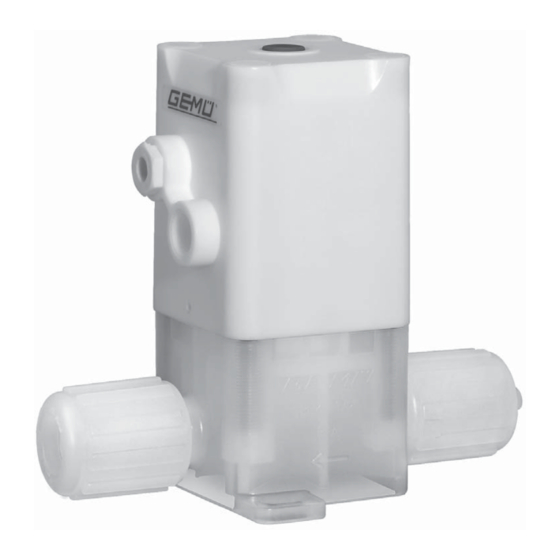
Seite 8: Geräteaufbau
Geräteaufbau 10.1 Montage des Membran-Sitzventils WARNUNG Unter Druck stehende Armaturen! ® Gefahr von schwersten Verletzungen oder Tod! Nur an druckloser Anlage arbeiten. WARNUNG Aggressive Chemikalien! ® Verätzungen! Montage nur mit geeigneter Schutzausrüstung. Geräteaufbau VORSICHT Heiße Anlagenteile! Ventilkörper ® Verbrennungen! Steuermediumanschluss 2 (NC) Nur an abgekühlter Anlage Antrieb arbeiten. - Seite 9 Installationsort: VORSICHT VORSICHT Befestigung mit geeigneten medienbeständigen Kunststoff - Membran-Sitzventil äußerlich nicht stark beanspruchen. Schrauben (nicht im Lieferumfang enthalten)! Installationsort so wählen, dass Membran-Sitzventil nicht als Steighilfe ® Korrosion und Kontamination bei Verwendung von Metall-Schrauben! genutzt werden kann. Rohrleitung so legen, dass Schub- und Biegungskräfte, sowie Vibrationen Montage bei Flare-Anschluss: und Spannungen vom Ventilkörper...
-
Seite 10: Bedienung
10.3 Steuerfunktionen Montage bei Schweißstutzen: GEFAHR Folgende Steuerfunktionen sind verfügbar: Austritt von extrem Steuerfunktion 1 gesundheitsschädlichen Dämpfen Federkraft geschlossen (NC): beim Verschweißen von PFA! Ruhezustand des Membran-Sitzventils: ® Schädigung der Atemwege, Verätzung / durch Federkraft geschlossen. Ansteuern Vergiftung! des Antriebs (Anschluss 2) öffnet das Absaugvorrichtung vor Schweißbeginn Membran-Sitzventil. -
Seite 11: Steuermedium Anschließen
10.4 Steuermedium anschließen 1. Antrieb in Off en-Position bringen. Wichtig: Hubbe- Steuermediumleitungen grenzung spannungs- und knickfrei montieren! Je nach Anwendung geeignete Kontermutter Anschlussstücke verwenden. Gewinde der Steuermediumanschlüsse: Antriebsgröße 0: Antriebsgröße 1 - 4: G1/8 Steuerfunktion Anschluss Federkraft geschlossen 2: Steuermedium (NC) (Öffnen) Federkraft geöffnet... -
Seite 12: Vorgehensweise Bei Antriebsgröße
Vorgehensweise bei Antriebsgröße Vorgehensweise bei Antriebsgröße 1 und 2: 3 und 4: 1. Antrieb in Off en-Position bringen. 1. Antrieb in Off en-Position bringen. 2. Rote optische Stellungsanzeige mit 2. Abdeckkappe entfernen: Flachzange herausziehen und entfernen. Schraubendreher 2,5 mm in vorgefertigte Schlitze (weiße Pfeile) der Abdeckkappe Optische Stellungs- stecken und Abdeckkappe vorsichtig... -
Seite 13: Montage / Demontage Von Ersatzteilen
11 Montage / Demontage von Ersatzteilen 11.1 Demontage des Antriebs vom Ventilkörper 1. Ist eine Hubbegrenzung montiert, diese demontieren (siehe Kapitel 10.5). 2. Antrieb A in Off en-Position bringen. 4. Abdeckkappe wieder aufstecken. Die 3. Abdeckkappen 39 mit Schraubendreher Verzahnungen von Abdeckkappe einstechen, vorsichtig nach oben hebeln und Antriebsinnerem müssen und entsorgen. -
Seite 14: Demontage Membrane
11.2 Demontage Membrane 5. Antrieb A vom Ventilkörper 1 abheben. 1. Antrieb A in Geschlossen-Position bringen. 2. Membrane 2 herausschrauben. 3. Alle Teile von Produktresten und Verschmutzungen reinigen. Teile dabei nicht zerkratzen oder beschädigen! 4. Alle Teile auf Beschädigungen prüfen. 5. -
Seite 15: Montage Membrane
11.3 Montage Membrane 11.3.1 Allgemeines Wichtig: Für Membran-Sitzventil passende Membrane einbauen (geeignet für Medium, Mediumkonzentration, Temperatur und Druck). Die Absperrmembrane ist ein Verschleißteil. Vor Inbetriebnahme und über gesamte Einsatzdauer des Membran-Sitzventils technischen Zustand und Funktion überprüfen. Zeitliche Abstände der Prüfung entsprechend den Einsatzbelastungen und / oder der für den Einsatzfall geltenden Regelwerken und Bestimmungen... - Seite 16 5. Innensechskantschrauben 18 über Kreuz festziehen (Drehmomente siehe unten). Antriebs- Schlüssel- Gewinde- Anzugs- größe weite durch- drehmo- messer ment [Nm] 0,22 0,70 1,10 2,00 4,15 6. Hubbegrenzung bei Bedarf wieder montieren (siehe Kapitel 10.5 "Einstellen der Hubbegrenzung"). 7. Neue Abdeckkappen 39 bündig in Antrieb A eindrücken.
- Seite 17 Antriebsgröße ® Das Membran-Sitzventil ist fertig 3 + 4 montiert. Antriebsgröße Antriebsgröße 1 + 2 8. Neue optische Stellungsanzeige bündig in Antrieb A eindrücken (nicht möglich bei Antriebsgröße 0). Wichtig: Der Antrieb muss in Geschlossen-Position sein. Antriebsgröße 3 + 4 Antriebsgröße 1 + 2 9.
-
Seite 18: Inbetriebnahme
12 Inbetriebnahme VORSICHT Wartungs- und WARNUNG Instandhaltungstätigkeiten nur durch Aggressive Chemikalien! geschultes Fachpersonal. ® Verätzungen! Für Schäden welche durch Vor Inbetriebnahme Dichtheit unsachgemäße Handhabung oder der Medienanschlüsse Fremdeinwirkung entstehen, übernimmt prüfen! GEMÜ keinerlei Haftung. Dichtheitsprüfung Nehmen Sie im Zweifelsfall vor nur mit geeigneter Inbetriebnahme Kontakt mit GEMÜ... -
Seite 19: Entsorgung
15 Entsorgung Hinweis zur Rücksendung: Aufgrund gesetzlicher Membran-Sitzventil vor Bestimmungen zum Schutz Entsorgung spülen. der Umwelt und des Personals Membran-Sitzventil ist es erforderlich, dass die entsprechend den Rücksendeerklärung vollständig Entsorgungsvorschriften / ausgefüllt und unterschrieben Umweltschutzbestimmungen den Versandpapieren beiliegt. entsorgen. Nur wenn diese Erklärung Auf Restanhaftungen vollständig ausgefüllt ist, wird die und Ausgasung von... - Seite 20 Fehler Möglicher Grund Fehlerbehebung Antrieb austauschen Antrieb defekt GEMÜ empfiehlt den Austausch der Membrane Antrieb demontieren, Membranmontage prüfen, Membrane falsch montiert ggf. Membrane austauschen Antrieb demontieren, Fremdkörper entfernen, Fremdkörper zwischen Membrane Membrane und Ventilkörper auf Beschädigungen und Ventilsitz untersuchen, ggf. Teile austauschen Hubbegrenzung ist falsch Hubbegrenzung neu einstellen (siehe Kapitel eingestellt...
-
Seite 21: Schnittbild
19 Schnittbild Abdeckkappen für Befestigungsschrauben Antrieb - Ventilkörper Optische Stellungsanzeige Antrieb Schließfeder Steuerfunktion 1 (Federkraft Anschluss 4 geschlossen (NC)) Steuermedium- Innensechskant- anschluss bei Steuer- schrauben funktion 2 (Federkraft geöffnet (NO)) / Ent- Verdrehsicherung lüftung für Steuer- Antriebskolben funktion 1 (Federkraft geschlossen (NC)) Vorspannfeder Dichtring des... -
Seite 22: Ersatzteile / Ersatzteilsets
20 Ersatzteile / Ersatzteilsets Benennung Inhalt Bestellbezeichnung 1 Membrane Membranset C50 M 5 ... HP 4 Abdeckkappen Benennung Inhalt Bestellbezeichnung 4 Schrauben Schraubenset C50 S30 ... 4 Abdeckkappen Benennung Inhalt Bestellbezeichnung Steuerfunktion 1: 9C50 4Z1 0A1 HPW, 1 Antrieb inkl. optischer Stellungsanzeige Antriebsset 9C50 4Z1 0B1 HPW* Antriebsgröße 0... -
Seite 23: Einbauerklärung
21 Einbauerklärung Einbauerklärung im Sinne der EG-Maschinenrichtlinie 2006/42/EG, Anh. II, 1.B für unvollständige Maschinen Hersteller: GEMÜ Gebr. Müller Apparatebau GmbH & Co. KG Postfach 30 Fritz-Müller-Straße 6-8 D-74653 Ingelfingen-Criesbach Beschreibung und Identifizierung der unvollständigen Maschine: Fabrikat: GEMÜ CleanStar-Sitzventil pneumatisch betätigt Seriennummer: ab 29.12.2009 Projektnummer:... -
Seite 24: Herstellererklärung
22 Herstellererklärung Herstellererklärung Gemäß Anhang VII der Richtlinie 2014/68/EU Wir, die Firma GEMÜ Gebr. Müller Apparatebau GmbH & Co. KG Fritz-Müller-Straße 6-8 D-74653 Ingelfingen erklären, dass unten aufgeführte Armaturen gemäß Artikel 4, Absatz 3 der Druckgeräterichtlinie 2014/68/EU in Übereinstimmung mit der guten Ingenieurpraxis ausgelegt und hergestellt sind. - Seite 48 GEMÜ Gebr. Müller Apparatebau GmbH & Co. KG · Fritz-Müller-Str. 6-8 · D-74653 Ingelfi ngen-Criesbach Telefon +49(0)7940/123-0 · Telefax +49(0)7940/123-192 · info@gemue.de · www.gemu-group.com...