Gemü 605 Original Einbau- Und Montageanleitung
Metall, dn 4 - 15
Vorschau ausblenden
Andere Handbücher für 605:
- Original einbau- und montageanleitung (36 Seiten) ,
- Original einbau- und montageanleitung (36 Seiten) ,
- Einbau- und montageanleitung (36 Seiten)

Verwandte Anleitungen für Gemü 605


Inhaltszusammenfassung für Gemü 605
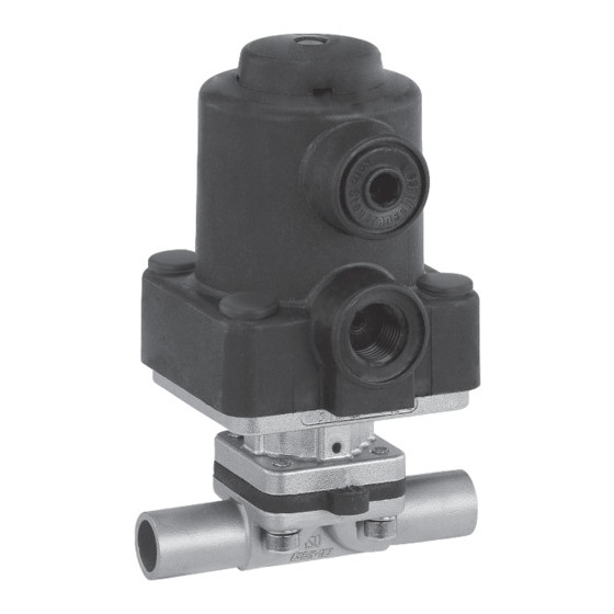
- Seite 1 Membranventil Metall, DN 4 - 15 Diaphragm Valve Metal, DN 4 - 15 ORIGINAL EINBAU- UND MONTAGEANLEITUNG INSTALLATION, OPERATING AND MAINTENANCE INSTRUCTIONS...
-
Seite 2: Inhaltsverzeichnis
Inhaltsverzeichnis Allgemeine Hinweise Voraussetzungen für die einwandfreie Allgemeine Hinweise Funktion des GEMÜ-Ventils: Allgemeine Sicherheitshinweise 2 Sachgerechter Transport und Lagerung Hinweise für Service- Installation und Inbetriebnahme durch und Bedienpersonal eingewiesenes Fachpersonal Warnhinweise Bedienung gemäß dieser Einbau- und Verwendete Symbole Montageanleitung Begriff sbestimmungen Ordnungsgemäße Instandhaltung Vorgesehener Einsatzbereich Technische Daten... -
Seite 3: Hinweise Für Service
Hinweise für Service- Warnhinweise und Bedienpersonal Warnhinweise sind, soweit möglich, nach folgendem Schema gegliedert: Die Einbau- und Montageanleitung enthält grundlegende Sicherheitshinweise, SIGNALWORT die bei Inbetriebnahme, Betrieb und Wartung zu beachten sind. Art und Quelle der Gefahr Nichtbeachtung kann zur Folge haben: ®... -
Seite 4: Verwendete Symbole
Vorgesehener Verwendete Symbole Einsatzbereich Gefahr durch heiße Oberfl ächen! Das GEMÜ-Membranventil 605 ist für den Einsatz in Rohrleitungen konzipiert. Gefahr durch ätzende Stoff e! Es steuert ein durchfl ießendes Medium indem es durch ein Steuermedium geschlossen oder geöff net werden kann. -
Seite 5: Steuerdruck
Temperaturen Medientemperatur FPM (Code 4A ) -10 bis 90 °C EPDM (Code 3A ) -10 bis 100 °C EPDM (Code 17) -10 bis 100 °C PTFE (TFM) (Code 5A ) -10 bis 100 °C Sterilisationstemperatur FPM (Code 4A ) nicht einsetzbar EPDM (Code 3A ) max. -
Seite 6: Bestelldaten
Bestelldaten Anschlussart Code Gehäuseform Code Gewindeanschluss Behälterkörper Gewindemuffe DIN ISO 228 Durchgang Gewindestutzen DIN 11851 Mehrwegeausführung Eine Seite Gewindestutzen, andere Seite T-Körper Kegelstutzen und Überwurfmutter, DIN 11851 * Abmessungen siehe Broschüre T-Ventile Sterilverschraubung auf Anfrage ** Abmessungen und Ausführungen auf Anfrage Ventilkörperwerkstoff Code Anschlussart... - Seite 7 Ventilkörper-Oberflächengüten, Innenkontur Hygiene- Designation Schmiedekörper Feinguss klasse ASME BPE Code Code 40, 42, F4 Code 32, 34 DIN 11866 (2014) Ra ≤ 6,3 μm (250 μinch) für medienberührte Oberflächen, 1500 innen/außen gestrahlt Ra ≤ 0,8 μm (30 μinch) für medienberührte Oberflächen, 1502 innen mechanisch poliert Ra ≤...
-
Seite 8: Herstellerangaben
Herstellerangaben Funktionsbeschreibung GEMÜ 605 ist ein Metall-Membranventil Transport mit Durchgangs-, T- Körper oder Behälterboden-Ablasskörper bzw. Membranventil nur auf geeignetem Ausführung in Mehrwegeausführung. Lademittel transportieren, nicht stürzen, Das Ventil besitzt einen wartungsarmen vorsichtig handhaben. Kolbenantrieb, der mit neutralen Gasen Verpackungsmaterial entsprechend... -
Seite 9: Geräteaufbau
Geräteaufbau VORSICHT Optische Heiße Anlagenteile! Stellungs- ® Verbrennungen! anzeige Nur an abgekühlter Anlage arbeiten. Steuer- medium- VORSICHT anschluss 4 Ventil nicht als Trittstufe oder Steuer- medium- Aufstiegshilfe benutzen! anschluss 2 ® Gefahr des Abrutschens / der Beschädigung des Ventils. VORSICHT Maximal zulässigen Druck nicht Geräteaufbau überschreiten! -
Seite 10: Bedienung
Klammer verbinden. Die Dichtung sowie die Klammer der Clampanschlüsse sind nicht im Lieferumfang enthalten. Wichtig: Schweißstutzen / Clampanschlüsse: Drehwinkel für das entleerungsoptimierte Einschweißen entnehmen Sie bitte der Broschüre "Drehwinkel für 2/2-Wege-Ventilkörper" (auf Anfrage oder unter www.gemu-group.com). 10 / 36... -
Seite 11: Steuerfunktionen
10.3 Steuerfunktionen Anschlüsse Steuerfunktion Folgende Steuerfunktionen sind verfügbar: 1 (NC) Steuerfunktion 1 2 (NO) Federkraft geschlossen (NC): 3 (DA) Ruhezustand des Ventils: durch + = vorhanden / - = nicht vorhanden Federkraft geschlossen. Ansteuern (Anschlüsse 2 / 4 siehe Bild links) des Antriebs (Anschluss 2) öffnet das 10.4 Steuermedium anschließen... -
Seite 12: Demontage Ventil (Antrieb Vom Körper Lösen)
11.1 Demontage Ventil Wichtig: (Antrieb vom Körper lösen) Für Ventil passende Membrane einbauen (geeignet für Medium, 1. Antrieb A in Off en-Position bringen. Mediumkonzentration, Temperatur 2. Antrieb A vom Ventilkörper 1 und Druck). Die Absperrmembrane demontieren. ist ein Verschleißteil. Vor 3. -
Seite 13: Montage Antrieb Auf Ventilkörper
Inbetriebnahme Werkstoff kennzeichung parallel zum Ventilkörpersteg ausrichten. WARNUNG 11.4 Montage Antrieb Aggressive Chemikalien! auf Ventilkörper ® Verätzungen! Vor Inbetriebnahme Dichtheit 1. Antrieb A in Off en-Position bringen. der Medienanschlüsse 2. Bei eingeknüpfter Membrane kontrollieren: prüfen! Dichtheitsprüfung Linke Druck- Rechte nur mit geeigneter stückhälfte Druckstück- hälfte... -
Seite 14: Demontage
Rücksendung VORSICHT Membranventil reinigen. Wartungs- und Rücksendeerklärung bei GEMÜ Instandhaltungstätigkeiten nur durch anfordern. geschultes Fachpersonal. Rücksendung nur mit vollständig Für Schäden welche durch ausgefüllter Rücksendeerklärung. unsachgemäße Handhabung oder Fremdeinwirkung entstehen, übernimmt Ansonsten erfolgt keine Gutschrift bzw. keine GEMÜ keinerlei Haftung. Erledigung der Reparatur Nehmen Sie im Zweifelsfall vor sondern eine kostenpflichtige Entsorgung. -
Seite 15: Fehlersuche / Störungsbehebung
Fehlersuche / Störungsbehebung Fehler Möglicher Grund Fehlerbehebung Steuermedium entweicht aus Entlüftungsbohrung* Antriebsabdichtung defekt Antrieb austauschen des Antriebs Steuermedium entweicht Antrieb austauschen und Steuermedium Spindelabdichtung undicht aus Leckagebohrung* auf Verschmutzungen untersuchen Betriebsmedium entweicht Absperrmembrane auf Beschädigungen Absperrmembrane defekt aus Leckagebohrung* prüfen, ggf. Membrane tauschen Steuermedium entweicht aus Anschluss 4* Kolbenabdichtung defekt... -
Seite 16: Schnittbild Und Ersatzteile
Schnittbild und Ersatzteile Anschluss 4 Anschluss 2 Entlüftungs- bohrung Leckagebohrung Pos. Benennung Bestellbezeichnung Ventilkörper K601... Membrane 600 8M... Schraube 605 8S30... Scheibe Antrieb 9605 8... 16 / 36... -
Seite 17: Einbauerklärung
29.12.2009 Projektnummer: MV-Pneum-2009-12 Handelsbezeichnung: Typ 605 Es wird erklärt, dass die folgenden grundlegenden Anforderungen der Maschinenrichtlinie 2006/42/EG erfüllt sind: 1.1.3.; 1.1.5.; 1.1.7.; 1.2.1.; 1.3.; 1.3.2.; 1.3.3.; 1.3.4.; 1.3.7.; 1.3.9.; 1.5.3.; 1.5.5.; 1.5.6.; 1.5.7.; 1.5.8.; 1.5.9.; 1.6.5.; 2.1.1.; 3.2.1.; 3.2.2.; 3.3.2.; 3.4.4.; 3.6.3.1.; 4.1.2.1.; 4.1.2.3.; 4.1.2.4.; 4.1.2.5.; 4.1.2.6. a); 4.1.2.6. b);... - Seite 34 34 / 36...
- Seite 35 35 / 36...
- Seite 36 GEMÜ Gebr. Müller Apparatebau GmbH & Co. KG · Fritz-Müller-Str. 6-8 · D-74653 Ingelfi ngen-Criesbach Telefon +49(0)7940/123-0 · Telefax +49(0)7940/123-192 · info@gemue.de · www.gemu-group.com...