Gemü 625 Original Einbau- Und Montageanleitung
Metall, dn 10 - 20
Vorschau ausblenden
Andere Handbücher für 625:
- Original einbau- und montageanleitung (40 Seiten) ,
- Original einbau- und montageanleitung (40 Seiten) ,
- Original einbau- und montageanleitung (40 Seiten)

Verwandte Anleitungen für Gemü 625


Inhaltszusammenfassung für Gemü 625
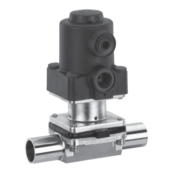
- Seite 1 Membranventil Metall, DN 10 - 20 Diaphragm Valve Metal, DN 10 - 20 ORIGINAL EINBAU- UND MONTAGEANLEITUNG INSTALLATION, OPERATING AND MAINTENANCE INSTRUCTIONS...
-
Seite 2: Inhaltsverzeichnis
Inhaltsverzeichnis Allgemeine Hinweise Voraussetzungen für die einwandfreie Allgemeine Hinweise Funktion des GEMÜ-Ventils: Allgemeine Sicherheitshinweise 2 Sachgerechter Transport und Lagerung Hinweise für Service- Installation und Inbetriebnahme durch und Bedienpersonal eingewiesenes Fachpersonal Warnhinweise Bedienung gemäß dieser Einbau- und Verwendete Symbole Montageanleitung Begriff sbestimmungen Ordnungsgemäße Instandhaltung Vorgesehener Einsatzbereich Technische Daten... -
Seite 3: Hinweise Für Service
Hinweise für Service- Warnhinweise und Bedienpersonal Warnhinweise sind, soweit möglich, nach Die Einbau- und Montageanleitung enthält folgendem Schema gegliedert: grundlegende Sicherheitshinweise, die bei SIGNALWORT Inbetriebnahme, Betrieb und Wartung zu beachten sind. Nichtbeachtung kann zur Art und Quelle der Gefahr Folge haben: ®... -
Seite 4: Verwendete Symbole
Verwendete Symbole Vorgesehener Einsatzbereich Das GEMÜ-Membranventil 625 ist für Gefahr durch heiße Oberfl ächen! den Einsatz in Rohrleitungen konzipiert. Es steuert ein durchfl ießendes Medium indem es durch ein Steuermedium Gefahr durch ätzende Stoff e! geschlossen oder geöff net werden kann. -
Seite 5: Technische Daten
Technische Daten Betriebsmedium Aggressive, neutrale, gasförmige und flüssige Medien, die die physikalischen und chemischen Eigenschaften des jeweiligen Gehäuse- und Membranwerkstof fes nicht negativ beeinflussen. Temperaturen Medientemperatur FPM (Code 4) -10 bis 90 °C EPDM (Code 13) -10 bis 100 °C EPDM (Code 17) -10 bis 100 °C PTFE (TFM) (Code 52) -
Seite 6: Bestelldaten
Bestelldaten Gehäuseform Code Ventilkörperwerkstoff Code Behälterkörper 1.4435 - BN2 (CF3M) - Feinguss Fe<0,5% Durchgang 1.4435 (ASTM A 351 CF3M ≙ 316L), Feinguss Mehrwegeausführung 1.4408, Feinguss T-Körper 1.4435 (316 L), Schmiedekörper 1.4435 (BN2), Schmiedekörper Fe<0,5% * Abmessungen siehe Broschüre T-Ventile 1.4539, Schmiedekörper ** Abmessungen und Ausführungen auf Anfrage Anschlussart Code... - Seite 7 Ventilkörper-Oberflächengüten, Innenkontur Hygiene- Designation Schmiedekörper Feinguss klasse ASME BPE Code Code 40, 42, F4 Code 32, 34 DIN 11866 (2014) Ra ≤ 6,3 μm (250 μinch) für medienberührte Oberflächen, 1500 innen/außen gestrahlt Ra ≤ 0,8 μm (30 μinch) für medienberührte Oberflächen, 1502 innen mechanisch poliert Ra ≤...
-
Seite 8: Herstellerangaben
Herstellerangaben Funktionsbeschreibung GEMÜ 625 ist ein Metall-Membranventil Transport mit Durchgangs-, T- oder Behälterboden- Membranventil nur auf geeignetem Ablasskörper bzw. Ausführung in Lademittel transportieren, nicht stürzen, Mehrwegeausführung. Das Ventil besitzt vorsichtig handhaben. einen wartungsarmen Kolbenantrieb, der Verpackungsmaterial entsprechend mit neutralen Gasen angesteuert werden den Entsorgungsvorschriften / kann. -
Seite 9: Montage Und Bedienung
10 Montage und Bedienung Installationsort: VORSICHT Vor Einbau: Ventilkörper- und Membranwerkstoff Ventil äußerlich nicht stark beanspruchen. entsprechend Betriebsmedium auslegen. Installationsort so wählen, dass Ventil Eignung vor Einbau prüfen! nicht als Steighilfe genutzt werden kann. Siehe Kapitel 5 "Technische Daten". Rohrleitung so legen, dass Schub- und Biegungskräfte, sowie Vibrationen und Spannungen vom Ventilkörper 10.1 Montage des... -
Seite 10: Bedienung
Steuerfunktion 2 bitte der Broschüre "Drehwinkel für Federkraft geöffnet (NO): 2/2-Wege-Ventilkörper" (auf Anfrage Ruhezustand des Ventils: durch Federkraft oder unter www.gemu-group.com). geöffnet. Ansteuern des Antriebs (Anschluss 4) schließt das Ventil. Entlüften Montage bei Gewindeanschluss: des Antriebs bewirkt das Öffnen des Ventils Gewindeanschluss entsprechend der durch Federkraft. -
Seite 11: Steuermedium Anschließen
11 Montage / Demontage Anschlüsse von Ersatzteilen Steuerfunktion 1 (NC) 2 (NO) 3 (DA) + = vorhanden / - = nicht vorhanden (Anschlüsse 2 / 4 siehe Bild oben) 10.4 Steuermedium anschließen Wichtig: Steuermediumleitungen spannungs- und knickfrei montieren! Je nach Anwendung geeignete Anschlussstücke verwenden. -
Seite 12: Demontage Membrane
11.2 Demontage Membrane Wichtig: Ist die Membrane nicht weit Wichtig: genug in das Verbindungsstück Vor Demontage der Membrane eingeschraubt, wirkt die bitte Antrieb demontieren, siehe Schließkraft direkt auf den "Demontage Ventil (Antrieb vom Membranpin und nicht über Körper lösen)". das Druckstück. Das führt zu Beschädigungen und frühzeitigem 1. -
Seite 13: Montage Der
11.3.2 Montage der Das Druckstück ist lose. Konkav-Membrane Druckstück und Antriebsflansch von unten gesehen: Druckstückaussparung Bild 1 Membranpin Membrandom Bild 2 1. Antrieb A in Geschlossen-Position bringen. 2. Druckstück lose auf Antriebsspindel aufsetzen, Aussparungen in 45° Führungen einpassen (siehe Kapitel 11.3.1 "Allgemeines"). -
Seite 14: Montage Antrieb Auf Ventilkörper
11.4 Montage Antrieb 12 Inbetriebnahme auf Ventilkörper WARNUNG 1. Antrieb A in Off en-Position bringen. Aggressive Chemikalien! 2. Antrieb A mit montierter Membrane 2 ® Verätzungen! auf Ventilkörper 1 aufsetzen. Vor Inbetriebnahme Dichtheit 3. Schrauben 18 mit Scheiben 19 bzw. der Medienanschlüsse Muttern (nur bei B-, M- und T-Körpern) prüfen! -
Seite 15: Demontage
16 Rücksendung VORSICHT Membranventil reinigen. Wartungs- und Rücksendeerklärung bei GEMÜ Instandhaltungstätigkeiten nur durch anfordern. geschultes Fachpersonal. Rücksendung nur mit vollständig Für Schäden welche durch ausgefüllter Rücksendeerklärung. unsachgemäße Handhabung oder Fremdeinwirkung entstehen, übernimmt Ansonsten erfolgt keine GEMÜ keinerlei Haftung. Gutschrift bzw. keine Nehmen Sie im Zweifelsfall vor Erledigung der Reparatur Inbetriebnahme Kontakt mit GEMÜ... -
Seite 16: Fehlersuche / Störungsbehebung
18 Fehlersuche / Störungsbehebung Fehler Möglicher Grund Fehlerbehebung Steuermedium entweicht aus Anschluss 4* bei Steuerfunktion Antriebskolben defekt Antrieb austauschen NC bzw. Anschluss 2* bei Steuerfunktion NO Steuermedium entweicht aus Antrieb austauschen und Steuermedium Spindelabdichtung undicht Leckagebohrung* auf Verschmutzungen untersuchen Betriebsmedium entweicht aus Absperrmembrane auf Beschädigungen Absperrmembrane defekt Leckagebohrung*... -
Seite 17: Schnittbild Und Ersatzteile
19 Schnittbild und Ersatzteile Anschluss 4 Anschluss 2 Leckagebohrung Pos. Benennung Bestellbezeichnung Ventilkörper K612... Membrane 600 10M... Schraube 625 10S30... Scheibe Antrieb 9625 10... 17 / 40... -
Seite 18: Einbauerklärung
29.12.2009 Projektnummer: MV-Pneum-2009-12 Handelsbezeichnung: Typ 625 Es wird erklärt, dass die folgenden grundlegenden Anforderungen der Maschinenrichtlinie 2006/42/EG erfüllt sind: 1.1.3.; 1.1.5.; 1.1.7.; 1.2.1.; 1.3.; 1.3.2.; 1.3.3.; 1.3.4.; 1.3.7.; 1.3.9.; 1.5.3.; 1.5.5.; 1.5.6.; 1.5.7.; 1.5.8.; 1.5.9.; 1.6.5.; 2.1.1.; 3.2.1.; 3.2.2.; 3.3.2.; 3.4.4.; 3.6.3.1.; 4.1.2.1.; 4.1.2.3.; 4.1.2.4.; 4.1.2.5.; 4.1.2.6. a); 4.1.2.6. b);... - Seite 19 19 / 40...
- Seite 37 37 / 40...
- Seite 38 38 / 40...
- Seite 39 39 / 40...
- Seite 40 GEMÜ Gebr. Müller Apparatebau GmbH & Co. KG · Fritz-Müller-Str. 6-8 · D-74653 Ingelfi ngen-Criesbach Telefon +49(0)7940/123-0 · Telefax +49(0)7940/123-192 · info@gemue.de · www.gemu-group.com...