Inhaltsverzeichnis
Werbung
Verfügbare Sprachen
Verfügbare Sprachen
Quicklinks
Werbung
Kapitel
Inhaltsverzeichnis
Fehlerbehebung

Verwandte Anleitungen für Gemü CleanStar C57 HPW iComLine


Inhaltszusammenfassung für Gemü CleanStar C57 HPW iComLine
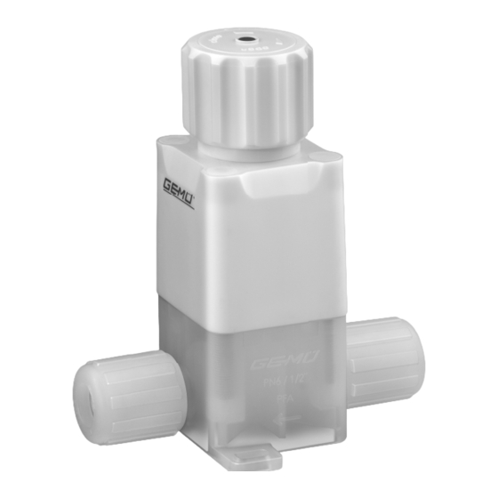
- Seite 1 CleanStar C57 HPW ® ® Membran-Sitzventil iComLine Kunststoff , 1/4" - 1 1/4" (DN 4 - 25) ® Diaphragm Globe Valve iComLine Plastic, 1/4" - 1 1/4" (DN 4 - 25) ORIGINAL EINBAU- UND MONTAGEANLEITUNG INSTALLATION, OPERATING AND MAINTENANCE INSTRUCTIONS C57 HPW...
-
Seite 2: Inhaltsverzeichnis
Inhaltsverzeichnis Allgemeine Hinweise Allgemeine Hinweise Voraussetzungen für die einwandfreie Allgemeine Sicherheitshinweise 2 Funktion des GEMÜ-Membran-Sitzventils: Hinweise für Service- Sachgerechter Transport und Lagerung und Bedienpersonal Installation und Inbetriebnahme durch Warnhinweise eingewiesenes Fachpersonal Verwendete Symbole Bedienung gemäß dieser Einbau- und Begriffsbestimmungen Montageanleitung Vorgesehener Einsatzbereich Ordnungsgemäße Instandhaltung Technische Daten... -
Seite 3: Hinweise Für Service
Hinweise für Service- Warnhinweise und Bedienpersonal Warnhinweise sind, soweit möglich, nach folgendem Schema gegliedert: Die Einbau- und Montageanleitung enthält grundlegende Sicherheitshinweise, die bei SIGNALWORT Inbetriebnahme, Betrieb und Wartung zu beachten sind. Nichtbeachtung kann zur Art und Quelle der Gefahr Folge haben: ®... -
Seite 4: Begriffsbestimmungen
Technische Daten Hand: Beschreibt allgemeine Hinweise und Empfehlungen. Betriebsmedium Aggressive, neutrale, gasförmige und flüssige Medien, Punkt: Beschreibt auszuführende - insbesondere Reinstmedien - die die physikalischen und chemischen Eigenschaften des jeweiligen Gehäuse- und Tätigkeiten. Membranwerkstoffes nicht negativ beeinflussen. ® Pfeil: Beschreibt Reaktion(en) auf Betriebsdruck Tätigkeiten. - Seite 5 Kv- / Cv-Werte Durchgangsventile Max. Anschluss Größe Betriebs- Gewicht Wert Wert druck Antriebs- Code Größe Anschlussart Code [bar/PSI] [l/min] intern. ausführung gal/min] Schlauch Flare 73, 75, 77 6,0 / 90 0,23 1/4" Schlauch Pillar Super 300 Type 6,0 / 90 0,28 Schlauch PrimeLock...
-
Seite 6: Bestelldaten
Zuordnung Antriebs- / Sitzgröße / Ausführung Sitzgröße Ø Antriebsgröße Ausführung Ø Sitzgröße [mm] 6,38 9,55 15,80 22,25 Bestelldaten Code Werkstoff Ventilkörper Code Manuell betätigt - Handrad (Multi Turn) PFA, Perfluoralkoxy (nur Flare- und PrimeLock-Anschluss) PTFE, Polytetrafluorethylen (nur Pillar-Anschluss) Nennweite Code 1/4"... -
Seite 7: Herstellerangaben
Herstellerangaben Öffnen der Verpackung Das GEMÜ Membran-Sitzventil ist zweifach in Plastikfolie verschweißt und in einen Transport Karton verpackt. Membran-Sitzventil nur auf geeignetem VORSICHT Lademittel transportieren, nicht stürzen, Kartonverpackung nicht im Reinraum vorsichtig handhaben. öffnen! Verpackungsmaterial entsprechend ® Kontaminationsgefahr! den Entsorgungsvorschriften / Umweltschutzbestimmungen entsorgen. -
Seite 8: Geräteaufbau
Geräteaufbau 10.1 Montage des Membran-Sitzventils WARNUNG Unter Druck stehende Armaturen! ® Gefahr von schwersten Verletzungen oder Tod! Nur an druckloser Anlage arbeiten. WARNUNG Aggressive Chemikalien! ® Verätzungen! Montage nur mit geeigneter Schutzausrüstung. Geräteaufbau VORSICHT Heiße Anlagenteile! Ventilkörper ® Verbrennungen! Handrad Nur an abgekühlter Anlage Antrieb arbeiten. - Seite 9 Installationsort: VORSICHT VORSICHT Befestigung mit geeigneten medienbeständigen Kunststoff - Membran-Sitzventil äußerlich nicht Schrauben (nicht im Lieferumfang stark beanspruchen. enthalten)! Installationsort so wählen, dass ® Korrosion und Kontamination bei Membran-Sitzventil nicht als Steighilfe Verwendung von Metall-Schrauben! genutzt werden kann. Rohrleitung so legen, dass Schub- und Biegungskräfte, sowie Vibrationen Montage bei Flare-Anschluss: und Spannungen vom Ventilkörper...
-
Seite 10: Bedienung
Montage bei Schweißstutzen: Beim Schließen des Ventils verhält es sich entsprechend in umgekehrter Reihenfolge. GEFAHR VORSICHT Austritt von extrem gesundheitsschädlichen Dämpfen Steigendes Handrad! beim Verschweißen von PFA! ® Gefahr von Quetschungen der Finger! ® Schädigung der Atemwege, Verätzung / Vergiftung! Absaugvorrichtung vor Schweißbeginn installieren. - Seite 11 3. Innensechskantschrauben 18 mit 4. Antrieb A vom Ventilkörper 1 abheben. passendem Schlüssel über Kreuz lösen und entfernen. Antriebsgröße Schlüsselweite Wichtig: Nach Demontage alle Teile von Verschmutzungen reinigen (Teile dabei nicht beschädigen). Teile auf Beschädigung prüfen, ggf. auswechseln (nur Originalteile von GEMÜ...
-
Seite 12: Demontage Membrane
11.2 Demontage Membrane 11.3 Montage Membrane 1. Antrieb A in Geschlossen-Position bringen. 11.3.1 Allgemeines 2. Membrane 2 herausschrauben. Wichtig: Für Membran-Sitzventil passende Membrane einbauen (geeignet für Medium, Mediumkonzentration, Temperatur und Druck). Die Absperrmembrane ist ein Verschleißteil. Vor Inbetriebnahme und über gesamte Einsatzdauer des Membran-Sitzventils technischen Zustand und Funktion überprüfen. -
Seite 13: Montage Der Membrane
11.3.2 Montage der Membrane 11.4 Montage Antrieb auf Ventilkörper 1. Neuen Antrieb A in Geschlossen- Position bringen. 1. Antrieb A in Off en-Position bringen. 2. Neue Membrane 2 auf das Gewinde e 2. Antrieb A mit montierter Membrane 2 auf des Antriebskolbens schrauben und Ventilkörper 1 aufsetzen. -
Seite 14: Austausch Der Optischen
4. Innensechskantschrauben 18 über Kreuz Wichtig: festziehen (Drehmomente siehe unten). Bei Montage eines Ersatzantriebs A die lose gelieferte optische Stellungsanzeige S gemäß Kapitel 11.5 "Austausch der optischen Stellungsanzeige" ab Punkt 3 montieren! 11.5 Austausch der optischen Stellungsanzeige Antriebsgröße 1 - 3: 1. - Seite 15 3. Neue optische Stellungsanzeige S Antriebsgröße 4: bündig mit dem oberen Ring in die neue 1. Antrieb A in Geschlossen-Position Abdeckkappe K einschrauben. bringen, Handrad H komplett zudrehen. 2. Abdeckkappe K mit Schraubendreher einstechen, vorsichtig mit optischer Stellungsanzeige S nach oben hebeln und entsorgen.
-
Seite 16: Funktionsprüfung
4. Neue optische Stellungsanzeige S 2. Komplett montiertes Membran-Sitzventil bündig mit dem oberen Ring der auf Dichtheit prüfen. Abdeckkappe K eindrücken. ® Das Membran-Sitzventil ist einsatzbereit. ® Die optische Stellungsanzeige S ist fertig Wichtig: Wartung und Service: montiert. Membranen setzen sich im Laufe der Zeit. -
Seite 17: Inspektion Und Wartung
Vor Reinigung bzw. vor Inbetriebnahme Der Betreiber muss regelmäßige der Anlage: Sichtkontrollen der Membran-Sitzventile Membran-Sitzventil auf Dichtheit und entsprechend den Einsatzbedingungen und Funktion prüfen (Membran-Sitzventil des Gefährdungspotenzials zur Vorbeugung schließen und wieder öff nen). von Undichtheit und Beschädigungen Bei neuen Anlagen und nach durchführen. -
Seite 18: Hinweise
17 Hinweise Hinweis zur Rücksendung: Aufgrund gesetzlicher Hinweis zur Bestimmungen zum Schutz Mitarbeiterschulung: der Umwelt und des Personals Zur Mitarbeiterschulung nehmen ist es erforderlich, dass die Sie bitte über die Adresse auf der Rücksendeerklärung vollständig letzten Seite Kontakt auf. ausgefüllt und unterschrieben den Versandpapieren beiliegt. -
Seite 19: Schnittbild
19 Schnittbild Optische Stellungsanzeige Handrad Abdeckkappen für Antriebskolben Befestigungsschrauben Antrieb - Ventilkörper Innensechskant- schrauben Schließfeder (nur bei Antriebsgröße 1 - 3) Vorspannfeder Dichtring Kolbenführung Überwurf- mutter Membranstößel Ventilkörperanschluss Ventilkörper Leckagebohrung Befestigungslaschen mit Toleranzausgleich C57 HPW 19 / 44... -
Seite 20: Ersatzteile / Ersatzteilsets
20 Ersatzteile / Ersatzteilsets Benennung Inhalt Bestellbezeichnung 1 Membrane Membranset C50 M 5 ... HP 4 Abdeckkappen Benennung Inhalt Bestellbezeichnung 4 Schrauben Schraubenset C50 S30 ... 4 Abdeckkappen Benennung Inhalt Bestellbezeichnung 1 Antrieb 1 optische Stellungsanzeige Antriebsset 9C57 ...Z 01A1 HPW, Antriebsgröße 1 9C57 ...Z 01B1 HPW* 1 Abdeckkappe... -
Seite 21: Herstellererklärung
21 Herstellererklärung Herstellererklärung Gemäß Anhang VII der Richtlinie 2014/68/EU Wir, die Firma GEMÜ Gebr. Müller Apparatebau GmbH & Co. KG Fritz-Müller-Straße 6-8 D-74653 Ingelfingen erklären, dass unten aufgeführte Armaturen gemäß Artikel 4, Absatz 3 der Druckgeräterichtlinie 2014/68/EU in Übereinstimmung mit der guten Ingenieurpraxis ausgelegt und hergestellt sind. - Seite 22 Contents General information General information Prerequisites to ensure that the GEMÜ General safety information diaphragm globe valve functions correctly: Information for service Correct shipping and storage and operating personnel Installation and commissioning by trained Warning notes personnel Symbols used Operation according to the installation, Definition of terms operating and maintenance instructions Intended area of use...
-
Seite 23: Information For Service And Operating Personnel
Information for service Warning notes and operating personnel Wherever possible, warning notes are The installation, operating and maintenance organised according to the following scheme: instructions contain fundamental safety information that must be observed during SIGNAL WORD commissioning, operation and servicing. Non-compliance with these instructions may Type and source of the danger cause:... -
Seite 24: Definition Of Terms
Technical data Hand: indicates general information and recommendations. Working medium Corrosive, inert, gaseous and liquid media - particularly high Bullet point: indicates the tasks to purity media - which have no negative impact on the physical and chemical properties of the body and diaphragm material. be performed. - Seite 25 Kv / Cv values - 2/2-way valves Max. Connection Size operating Weight value value pressure Bonnet Code Size Connection Code [bar/PSI] [l/min] intern. version gal/min] Tube Flare 73, 75, 77 6.0 / 90 0.23 1/4” Tube Pillar Super 300 Type 6.0 / 90 0.28 Tube...
-
Seite 26: Order Data
Correlation bonnet size / seat size / version Seat size Ø Bonnet size Version Ø seat size [mm] 6.38 9.55 15.80 22.25 Order data Type Code Valve body material Code Manually operated - Handwheel (Multi Turn) PFA, perfluoralkoxy (only flare and PrimeLock connections) PTFE, polytetrafluoroethylene (only Pillar connection) Nominal size Code... -
Seite 27: Manufacturer's Information
Manufacturer’s information Opening the packaging The GEMÜ diaphragm globe valve is sealed in two plastic bags and packed in a box. Transport CAUTION Only transport the diaphragm globe valve by suitable means. Do not drop. Handle Do not open box in the cleanroom! carefully. -
Seite 28: Construction
Construction 10.1 Installing the diaphragm globe valve WARNING The equipment is subject to pressure! ® Risk of severe injury or death! Only work on depressurized plant. WARNING Corrosive chemicals! ® Risk of caustic burns! Wear appropriate protective gear when installing. CAUTION Construction Hot plant components! - Seite 29 Installation location: CAUTION CAUTION Fastening with suitable media Do not apply external force to the resistant plastic bolts (not included in the scope of delivery)! diaphragm globe valve. ® Corrosion and contamination when Choose the installation location so that the diaphragm globe valve cannot be using metal bolts! used as a foothold (climbing aid).
-
Seite 30: Operation
Installation - Butt weld spigots: When the valve is open and the handwheel is turned to the closed position, the reverse DANGER order applies. Vapor fumes from PFA welding can CAUTION cause health related issues! ® Risk of damage to respiratory tracts, Rising handwheel! caustic burns / poisoning! ®... - Seite 31 3. Diagonally loosen and remove the Allen 4. Lift off bonnet A from valve body 1. bolts 18 with a suitable key. Bonnet size Wrench size Important: After disassembly, clean all parts of contamination (do not damage parts). Check parts for potential damage, replace if necessary (only use genuine parts from GEMÜ).
-
Seite 32: Removing The Diaphragm
11.2 Removing the diaphragm 11.3 Mounting the diaphragm 1. Move bonnet A to the closed position. 2. Unscrew diaphragm 2. 11.3.1 General information Important: Mount the correct diaphragm that suits the diaphragm globe valve (suitable for medium, medium concentration, temperature and pressure). -
Seite 33: Mounting The Diaphragm
11.3.2 Mounting the diaphragm 11.4 Bonnet mounting on valve body 1. Move new bonnet A to the closed position. 1. Move bonnet A to the open position. 2. Screw new diaphragm 2 on thread e of 2. Position bonnet A with the mounted the bonnet piston and tighten to hand- diaphragm 2 on the valve body 1. -
Seite 34: Replacing The Optical Position Indicator
4. Fully tighten the Allen bolts 18 diagonally Important: (see below for torques). When mounting a replacement bonnet A please assemble the loosely supplied optical position indicator S according to chapter 11.5 "Replacing the optical position indicator" from point 3! 11.5 Replacing the optical position indicator Bonnet size 1 - 3:... - Seite 35 3. Screw the new optical position Bonnet size 4: indicator S into the new cap K until it is 1. Move bonnet A to the closed position, fl ush with the upper ring of the cap. fully tighten handwheel H. 2.
-
Seite 36: Functional Test
4. Push in new optical position indicator S 2. Check tightness of completely until it is fl ush with the upper ring of assembled diaphragm globe valve. cap K. ® The diaphragm globe valve is ready for use. ® The optical position indicator S is Important: completely assembled. -
Seite 37: Inspection And Servicing
Prior to cleaning or commissioning the When ordering the diaphragm globe plant: valve, please state the complete Check the tightness and the function of order number. the diaphragm globe valve (close and reopen the diaphragm globe valve). If the plant is new and after repairs rinse 14 Disassembly the piping system with a fully opened diaphragm globe valve (to remove any... -
Seite 38: Information
17 Information Note for returns: Legal regulations for the protection Note on staff training: of the environment and personnel Please contact us at the address require that the completed and on the last page for staff training signed goods return declaration information. -
Seite 39: Sectional Drawing
19 Sectional drawing Optical position indicator Handwheel Protective caps Piston for sealing bolts on bonnet - valve body Allen screws Closing spring (only for bonnet size 1 - 3) Pre-tension spring Gasket Piston guidance Union Diaphragm tappet Valve body connection Valve body Leak detection hole Variable mounting lug... -
Seite 40: Spare Parts / Spare Parts Kits
20 Spare parts / Spare parts kits Name Content Order description 1 diaphragm Diaphragm kit C50 M 5 ... HP 4 caps Name Content Order description 4 screws Screw kit C50 S30 ... 4 caps Name Content Order description 1 bonnet 1 optical position indicator Bonnet kit 9C57 ...Z 01A1 HPW,... -
Seite 41: Manufacturer's Declaration
21 Manufacturer's declaration Manufacturer's declaration According to annex VII of the Directive 2014/68/EU Hereby we, GEMÜ Gebr. Müller Apparatebau GmbH & Co. KG Fritz-Müller-Straße 6-8 D-74653 Ingelfingen declare that the equipment listed below is designed and manufactured in compliance with the sound engineering practice according to section 4, paragraph 3 of the Pressure Equipment Directive 2014/68/EU. - Seite 42 C57 HPW 42 / 44...
- Seite 43 C57 HPW 43 / 44...
- Seite 44 GEMÜ Gebr. Müller Apparatebau GmbH & Co. KG · Fritz-Müller-Str. 6-8 · D-74653 Ingelfi ngen-Criesbach Telefon +49(0)7940/123-0 · Telefax +49(0)7940/123-192 · info@gemue.de · www.gemu-group.com...