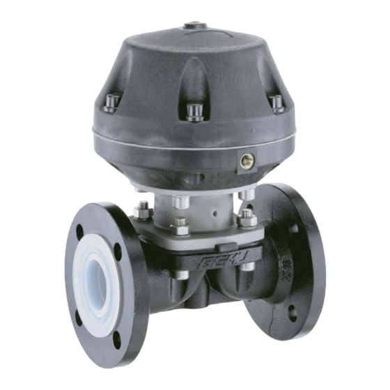
Gemü 687 Original Einbau- Und Montageanleitung
Metall, dn 10 - 100
Vorschau ausblenden
Andere Handbücher für 687:
- Betriebsanleitung (88 Seiten) ,
- Original einbau- und montageanleitung (48 Seiten) ,
- Montageanleitung (40 Seiten)

Verwandte Anleitungen für Gemü 687


Inhaltszusammenfassung für Gemü 687
- Seite 1 Membranventil Metall, DN 10 - 100 Diaphragm Valve Metal, DN 10 - 100 ORIGINAL EINBAU- UND MONTAGEANLEITUNG INSTALLATION, OPERATING AND MAINTENANCE INSTRUCTIONS...
-
Seite 2: Inhaltsverzeichnis
Inhaltsverzeichnis Allgemeine Hinweise Voraussetzungen für die einwandfreie Allgemeine Hinweise Funktion des GEMÜ-Ventils: Allgemeine Sicherheitshinweise 2 Sachgerechter Transport und Lagerung Hinweise für Service- Installation und Inbetriebnahme durch und Bedienpersonal eingewiesenes Fachpersonal Warnhinweise Bedienung gemäß dieser Einbau- und Verwendete Symbole Montageanleitung Begriff sbestimmungen Ordnungsgemäße Instandhaltung Vorgesehener Einsatzbereich Korrekte Montage, Bedienung und Wartung... -
Seite 3: Warnhinweise
Gefährdung von Personen durch Warnhinweise sind dabei immer mit elektrische, mechanische und chemische einem Signalwort und teilweise auch Einwirkungen. mit einem gefahrenspezifischen Symbol Gefährdung von Anlagen in der gekennzeichnet. Umgebung. Folgende Signalwörter bzw. Versagen wichtiger Funktionen. Gefährdungsstufen werden eingesetzt: Gefährdung der Umwelt durch Austreten GEFAHR gefährlicher Stoff... -
Seite 4: Begriff Sbestimmungen
Steuerfunktion 2 0,03 dm³ 0,02 dm³ Vorgesehener Einsatzbereich 0,15 dm³ 0,11 dm³ 0,26 dm³ 0,23 dm³ Das GEMÜ-Membranventil 687 ist für 0,73 dm³ 0,54 dm³ 2,30 dm³ 1,87 dm³ den Einsatz in Rohrleitungen konzipiert. 2,30 dm³ 2,00 dm³ Es steuert ein durchfl ießendes Medium Stf. - Seite 5 Steuer- / Betriebsdruckdiagramm Steuerfunktion 2 MG 100 MG 40 MG 80 MG 25 MG 50 Betriebsdruck [bar] Betriebsdruck [bar] Steuerfunktion 1 Steuerfunktion 2 Steuerfunktion 3 Betriebsdruck [bar] / Steuer- Betriebsdruck [bar] / Steuer- Betriebsdruck [bar] / Steuer- Membranwerkstoff druck Membranwerkstoff druck Membranwerkstoff druck...
-
Seite 6: Bestelldaten
Stutzen ANSI/ASME B36.19M, Schedule 40s PTFE / EPDM, PTFE kaschiert Gewindeanschluss Gewindemuffe DIN ISO 228 Zuordnung siehe Übersichtstabelle Datenblatt GEMÜ 687 Seite 12 Gewindestutzen DIN 11851 Material entspricht FDA Vorgaben, ausgenommen Code 4 und 14 Eine Seite Gewindestutzen, andere Seite Die Kombinationen von PFA-Auskleidungen mit 5E-Membranen Kegelstutzen und Überwurfmutter, DIN 11851... -
Seite 7: Herstellerangaben
Passendes, funktionsfähiges und sicheres Werkzeug benutzen. Lieferung und Leistung Ware unverzüglich bei Erhalt auf Funktionsbeschreibung Vollständigkeit und Unversehrtheit GEMÜ 687 ist ein Metall-Membranventil überprüfen. mit Durchgangs-, T- oder Behälterboden- Lieferumfang aus Versandpapieren, Ablasskörper bzw. Ausführung in Ausführung aus Bestellnummer Mehrwegeausführung. Das Ventil besitzt ersichtlich. -
Seite 8: Geräteaufbau
10 Geräteaufbau VORSICHT Heiße Anlagenteile! ® Verbrennungen! Nur an abgekühlter Anlage arbeiten. VORSICHT Ventil nicht als Trittstufe oder Steuer- Aufstiegshilfe benutzen! medium- anschluss ® Gefahr des Abrutschens / der Beschädigung des Ventils. VORSICHT Maximal zulässigen Druck nicht überschreiten! ® Eventuell auftretende Druckstöße Geräteaufbau (Wasserschläge) durch Schutzmaßnahmen vermeiden. -
Seite 9: Steuerfunktionen
Einschweißen entnehmen Sie bitte der Broschüre "Drehwinkel Ruhezustand des Ventils: durch Federkraft für 2/2-Wege-Ventilkörper" geschlossen. Ansteuern des Antriebs (auf Anfrage oder unter (Anschluss 2) öffnet das Ventil. Entlüften des www.gemu-group.com). Antriebs bewirkt das Schließen des Ventils durch Federkraft. 9 / 40... -
Seite 10: Steuermedium Anschließen
11.3 Steuermedium anschließen Steuerfunktion 2 Federkraft geöffnet (NO): Wichtig: Ruhezustand des Ventils: durch Federkraft Steuermediumleitungen geöffnet. Ansteuern des Antriebs spannungs- und knickfrei (Anschluss 4) schließt das Ventil. Entlüften montieren! des Antriebs bewirkt das Öffnen des Ventils Je nach Anwendung geeignete durch Federkraft. -
Seite 11: Demontage Ventil (Antrieb Vom Körper Lösen)
12.1 Demontage Ventil 12.3 Montage Membrane (Antrieb vom Körper lösen) 1. Antrieb A in Off en-Position bringen. 12.3.1 Allgemeines 2. Antrieb A vom Ventilkörper 1 demontieren. Wichtig: 3. Antrieb A in Geschlossen-Position Für Ventil passende Membrane bringen. einbauen (geeignet für Medium, Mediumkonzentration, Temperatur Wichtig: und Druck). -
Seite 12: Verdrehsicherung Der Spindel Am Druckstück
Das Druckstück ist bei Membrangrößen Membrangröße 25 - 80 (DN 15 - 80): 10 - 80 (DN 10 - 80) lose. Druckstück und Antriebsflansch von unten Bei Membrangröße 100 (DN 100) ist das gesehen: Druckstück fest montiert. Membrangröße 10 (DN 10 - 20): Druckstück und Antriebsflansch von unten gesehen: 45°... -
Seite 13: Montage Der Konkav-Membrane
12.3.2 Montage der 4. Neuen Membranschild von Hand Konkav-Membrane umklappen; bei großen Nennweiten saubere, gepolsterte Unterlage Druckstückaussparung verwenden. Membranpin Membrandom Membranschild Membranpin 1. Antrieb A in Geschlossen-Position III. bringen. 2. Bei Membrangröße 10 - 80 (DN 10 - 80) Druckstück lose auf Antriebsspindel 5. -
Seite 14: Montage Antrieb Auf Ventilkörper
12.4 Montage Antrieb VORSICHT auf Ventilkörper Gegen Leckage vorbeugen! 1. Antrieb A in Off en-Position bringen. Schutzmaßnahmen gegen 2. Antrieb A mit montierter Membrane 2 Überschreitung des maximal auf Ventilkörper 1 aufsetzen, auf zulässigen Drucks durch eventuelle Übereinstimmung von Membransteg und Druckstöße (Wasserschläge) vorsehen. -
Seite 15: Demontage
17 Rücksendung 1. Geeignete Schutzausrüstung gemäß den Regelungen des Anlagenbetreibers Membranventil reinigen. berücksichtigen. Rücksendeerklärung bei GEMÜ 2. Anlage bzw. Anlagenteil stilllegen. anfordern. 3. Gegen Wiedereinschalten sichern. Rücksendung nur mit vollständig 4. Anlage bzw. Anlagenteil drucklos ausgefüllter Rücksendeerklärung. schalten. Ansonsten erfolgt keine Der Betreiber muss regelmäßige Gutschrift bzw. -
Seite 16: Fehlersuche / Störungsbehebung
19 Fehlersuche / Störungsbehebung Fehler Möglicher Grund Fehlerbehebung Steuermedium entweicht aus Entlüftungsbohrung* im Oberteil des Antriebs bei Steuerfunktion NC bzw. Steuermembrane defekt Antrieb austauschen Anschluss 2 (siehe Kapitel 11.2 " Steuerfunktionen") bei Steuerfunktion NO Steuermedium entweicht aus Antrieb austauschen und Steuermedium Spindelabdichtung undicht Leckagebohrung* auf Verschmutzungen untersuchen... -
Seite 17: Schnittbild Und Ersatzteile
20 Schnittbild und Ersatzteile Entlüftungs- bohrung Steuer- membrane Leckagebohrung Pos. Benennung Bestellbezeichnung Ventilkörper K600... Membrane 600...M Schraube Scheibe 687...S30... Mutter Antrieb 9687... 17 / 40... -
Seite 18: Einbauerklärung
29.12.2009 Projektnummer: MV-Pneum-2009-12 Handelsbezeichnung: Typ 687 Es wird erklärt, dass die folgenden grundlegenden Anforderungen der Maschinenrichtlinie 2006/42/EG erfüllt sind: 1.1.3.; 1.1.5.; 1.1.7.; 1.2.1.; 1.3.; 1.3.2.; 1.3.3.; 1.3.4.; 1.3.7.; 1.3.9.; 1.5.3.; 1.5.5.; 1.5.6.; 1.5.7.; 1.5.8.; 1.5.9.; 1.6.5.; 2.1.1.; 3.2.1.; 3.2.2.; 3.3.2.; 3.4.4.; 3.6.3.1.; 4.1.2.1.; 4.1.2.3.; 4.1.2.4.; 4.1.2.5.; 4.1.2.6. a); 4.1.2.6. b);... -
Seite 19: Eg-Konformitätserklärung
GEMÜ Gebr. Müller GmbH & Co. KG Fritz-Müller-Straße 6-8 D-74653 Ingelfingen erklären, dass unten aufgeführte Armaturen die Sicherheitsanforderungen der Druckgeräte- richtlinie 97/23/EG erfüllen. Benennung der Armaturen - Typenbezeichnung Membranventil GEMÜ 687 Benannte Stelle: TÜV Rheinland Berlin Brandenburg Nummer: 0035 Zertifikat-Nr.: 01 202 926/Q-02 0036 Konformitätsbewertungsverfahren:... - Seite 38 38 / 40...
- Seite 39 39 / 40...
- Seite 40 VENTIL-, MESS- UND REGELSYSTEME VALVES, MEASUREMENT AND CONTROL SYSTEMS GEMÜ Gebr. Müller Apparatebau GmbH & Co. KG · Fritz-Müller-Str. 6-8 · D-74653 Ingelfi ngen-Criesbach Telefon +49(0)7940/123-0 · Telefax +49(0)7940/123-192 · info@gemue.de · www.gemu-group.com...