Wohler Econometer E 98 Bedienungsanleitung
Inhaltsverzeichnis
Verfügbare Sprachen
Verfügbare Sprachen
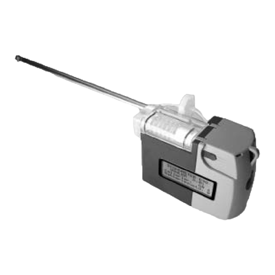
Econometer E 98
TÜV By RgG 195
TÜV By RgG 195
TÜV By RgG 195
TÜV By RgG 195
TÜV By RgG 195
Inhalt
1. Spezifikation ........................................... 2
2. Bedienelemente ..................................... 4
3. Kalibrieren und Messen ...................... 5
4. Handhabung ........................................... 9
5. Betrieb und Wartung .......................... 13
6. Zubehör .................................................. 15
7. Einstellungen ........................................ 16
8. Rechenformeln ..................................... 18
9. Ersatzteilliste + Garantie ................... 20
10. Konformitätserklärung ....................... 21
11. Kurzanleitung ....................................... 22
27. 01. 2003
Kapitel
Inhaltsverzeichnis

Verwandte Anleitungen für Wohler Econometer E 98


Inhaltszusammenfassung für Wohler Econometer E 98
-
Seite 1: Inhaltsverzeichnis
Econometer E 98 TÜV By RgG 195 TÜV By RgG 195 TÜV By RgG 195 TÜV By RgG 195 TÜV By RgG 195 Inhalt 6. Zubehör ..........15 1. Spezifikation ........... 2 7. Einstellungen ........16 2. Bedienelemente ........4 8. -
Seite 2: Spezifikation
1. Spezifikation Bedienungsanleitung Spezifikation Das Econometer E 98 ist ein handliches Abgasanalysegerät mit integrierter Gasauf- bereitung zur Durchführung von Messungen und Berechnungen, die zur Beurteilung von Heizungsanlagen notwendig sind. Die Messungen entsprechen der „Allgemeinen Ver- waltungsvorschrift zur Verordnung zur Durchführung des Bundes-Immissions- schutzgesetzes an Feuerstätten mit flüssigen und gasförmigen Brennstoffen“... -
Seite 3: Errechnete Werte
1. Spezifikation Bedienungsanleitung Messbereich:- 19,9 bis + 99,9 °C Genauigkeit: entsprechend den Anforderungen der BImSchV 1.2. Errechnete Werte: • Abgasverlust in % in Abhängigkeit vom Brennstoff nach BImSchV (QA) • ETA: Wirkungsgrad von 0 bis 120 % • : Kohlendioxid - Gehalt in % •... -
Seite 4: Bedienelemente
2. Bedienelemente Bedienungsanleitung Bedienelemente 1 Display 2 Ladebuchse 3 Ein-/ Aus- und Bedientaster 4 Anschluß Verbrennungslufttemperaturfühler (auf der Unterseite) 5 Druckanschluß für Einstellarbeiten am Brenner 6 Batteriefach (an der Seite des Gerätes) 7 Infrarot-Schnittstelle (an der Seite, schräg über dem Batteriefach des Gerätes) (Optional mit IRDA-Schnittstelle) 8 Wasserstopp-Filter 9 Wattefilter... -
Seite 5: Kalibrieren Und Messen
Das Econometer wird durch Betätigen des Tasters eingeschaltet. Nun sendet das E 98 die letzten 10 gespeicherten Messungen über die IRDA-Schnittstelle zum PC, Abbildung 1. Dieser Vorgang dauert ungefähr 5 sec (nur mit IRDA-Schnittstelle). ECONOMETER E 98 Abbildung 1 WÖHLER D. 04 IR Datenübertragung... - Seite 6 3. Kalibrieren und Messen Bedienungsanleitung Durch einmaliges Drücken des Bedientasters wird der Menüpunkt gewechselt, durch Doppelklick auf „JA“ wird der Brennstoff der letzten Messung bestätigt, bei Doppelklick auf „NEIN“ kann zwischen folgenden Brennstoffen gewählt werden: (Abb. 3) Heiz- öl; Erdgas; Flüssiggas; Stadtgas; Holz; Kohle Brstoff: ZURÜCK Heizöl...
- Seite 7 3. Kalibrieren und Messen Bedienungsanleitung Wenn die Werte Abgastemperatur (TA) und Sauerstoffgehalt (O ) stabil sind, werden durch Doppelklick des Bedientasters die Werte „eingefroren“. In der Mitte läuft senkrecht die Buchstabenfolge „P A U S E“. Die Werte können notiert werden. Mit einem weiteren Doppel- klick wird die Messung fortgesetzt.
- Seite 8 3. Kalibrieren und Messen Bedienungsanleitung vorgenommen werden sollen (siehe unter 4. Seperater Druckanschluss). Drucknullung: Gerät drucklos Abbildung 9 machen, dann <TASTE> Nach Tastendruck kann der Schornsteinzug oder Brennergasdüsendruck gemessen wer- den. Bei konstanten Druckwerten können Sie mit Tasendruck die Messung beenden, siehe Abb.9.
-
Seite 9: Einstellungen Pc (Nur Mit Irda-Schnittstelle)
Druckerausgabe Abbildung 12 läuft Während des Druckvorganges kann das Econometer E 98 nicht bedient werden. Nach der Druckerausgabe schaltet das Gerät in den ursprünglichen Zustand ( Anzeigenfeld 1, siehe Abb. 4, - P A U S E). Dat->PC (nur mit IRDA-Schnittstelle) Wird im 3. - Seite 10 3. Kalibrieren und Messen Bedienungsanleitung YYYY X steht für eine Kanalnummer und Y steht für einen Wert des jeweiligen Kanals. Folgende Kanalnummer steht für einen Mess- oder Rechenwert: PD in Pa PD in hPa Ausschalten Bevor das Gerät ausgeschaltet wird, muss es mit ausreichend Frischluft gespült werden. Erst dann kann der Taster ca.
-
Seite 11: Handhabung Des Messgerätes
4. Handhabung Bedienungsanleitung Handhabung des Messgerätes 4.1. Verbrennungslufttemperatursonde und -fühler Die Verbrennungslufttemperatursonde soll nicht am Kabel aus der Buchse oder von der Unterlage gezogen werden. Der Anschluss für den Verbrennungslufttemperaturfühler, die Steckerform und die Verbrennungslufttemperatursonde befindet sich an der Unterseite des Gerätes. -
Seite 12: Batterie- Oder Akkuentsorgung
4. Handhabung Bedienungsanleitung Batterie- oder Akkuentsorgung Schadhafte Batterien oder Akkus, die aus dem Gerät genommen werden, können sowohl im Werk, als auch an Rücknahmestellen der öffentlich-rechtlichen Entsorgungsträger oder an Verkaufsstellen für Neubatterien oder Akkus, abgegeben werden. Kondensat Das Messgerät sollte nicht mit feuchtem Abgas beaufschlagt werden, wenn es für länge- re Zeit (z. -
Seite 13: Betrieb Und Wartung
Seiten gelöst werden. Der Filter kann problemlos getauscht wer- den, die Schlauchverbindungen müssen wieder dicht aufgesteckt werden. Die O-Ringe 14 x 1,78 (Dichtungen) des Wärmetauschers (Kondensatspirale) müssen regelmäßig mit Spezialpflegeöl behandelt werden, damit sie gängig bleiben. O-Ring Econometer E 98 Wattefilter 14 x 1,78 Kondensat- spirale... - Seite 14 Die Sonde und das Messgerät werden optisch auf Verschmutzungen, Niederschläge etc. kontrolliert. Messzellen Die Messwerte des Econometer E 98 werden durch eine elektrochemische Messzelle ), einen Halbleiter CO-Indikator (CO) sowie eine Halbleitermembran (PD) ermittelt. Die -Messzelle unterliegt einem Verschleiß. Die Lebensdauer der Messzellen hängt von vielen äußeren Parametern, wie der Pflege des Gerätes (Entfernen von Kondensat), der Benutzungshäufigkeit (Beaufschlagung mit...
-
Seite 15: Zubehör
9611 • Verbrennungslufttemperatursonde, 100 mm Best.-Nr. 9651 • Messschlauch zur Druckeinstellung am Brenner, 1m lang Best.-Nr. 9867 • Econometer E 98 mit Abgassonde 345 mm Best.-Nr. 9807 6.2 Sondenbefestigungen: • Schwenksondenhalter Best.-Nr. 2491 zur sicheren Befestigung der Sonde • Klemmkonus Best.-Nr. -
Seite 16: Einstellungen
7. Einstellungen Bedienungsanleitung Einstellungen, Setup Um in das Konfigurations-Menü zu gelangen, müssen Sie: A) Menüpunkt „CO-MESS“ aufrufen und bestätigen, B) dann den Taster gedrückt halten wie beim Ausschalten, aber... C) während der 2. Sekunde der Ausschaltfunktion Taster loslassen und sofort noch einmal drücken. - Seite 17 7. Einstellungen Bedienungsanleitung Drittes Anzeigenfeld: COkal (Kalibrierungswert für den CO-Indikator) COkal: Abbildung 17 Abbruch Der COkal-Kalibrierungswert wird wie oben beschrieben (siehe 7.1) eingestellt. Dieses Einstellungs-Menü soll nur zum Nachjustieren des CO-Indikators verwendet wer- den. Höherer Offsetwert Erhöhung der CO-Anzeige Niedriger Offsetwert Niedrigere Anzeige Sobald das Setup-Menü...
-
Seite 18: Rechenformeln
8. Rechenformeln Bedienungsanleitung Rechenformeln Der Abgasverlust wird nach folgender Formel berechnet, wobei neben den brennstoff- spezifischen Faktoren (A und B) auch der gemessene O - Wert, die Abgastemperatur (TA) und die Verbrennungslufttemperatur (TL oder Tl) in die Berechnung (Gleichung 8.1) einfließen. - Seite 19 8. Rechenformeln Bedienungsanleitung Die Luftverhältniszahl (Lam) errechnet sich nach Gleichung 8.3: 21,0 (8.3) 21,0 - O Die unverdünnte Kohlenmonoxidkonzentration (CO ) wird mit dem gemessenen CO- norm und O -Wert berechnet. 21,0 = CO (8.4) norm 21,0 - O Der Taupunkt (TP) wird über eine Formel errechnet, die die stöchiometrische Zusammen- setzung des Brennstoffes, eine angenommene relative Luftfeuchtigkeit sowie einen mitt- leren Luftdruck berücksichtigt.
-
Seite 20: Einzelteile
Best.-Nr. 9806 Garantie Jedes Econometer E 98 wird in allen Funktionen geprüft und verlässt unser Werk erst nach einer ausführlichen Qualitätskontrolle. Die Endkontrolle wird in einem Prüfbericht detailliert festgehalten und bei uns im Hause hinterlegt. Bei sachgemäßem Gebrauch beträgt die Garantiezeit auf das Messgerät und die Sonde 12 Monate ab Verkaufsdatum. -
Seite 21: Konformitätserklärung
Bedienungsanleitung 10. Konformitätserklärung Für das folgend bezeichnete Produkt: Econometer E 98 wird hiermit bestätigt, dass es den wesentlichen Schutzanforderungen entspricht, die in den Richtlinien des Rates zur Angleichung der Rechtsvorschriften der Mitglieds- staaten über die elektromagnetische Verträglichkeit (89/336/EWG und 93/97/EWG) fest gelegt sind. -
Seite 22: Kurzanleitung
Gerät geht aus 1. Schritt: Einschalten und Kalibrieren Das Econometer E 98 wird durch Drücken des Tasters eingeschaltet. Nach Ablauf der Kalibrierzeit wird der letzte genutzte Brennstoff gezeigt. Er kann mit Doppelklick auf „JA“ bestätigt oder mit Doppelklick auf „NEIN“ verändert werden. - Seite 92 Bedienungsanleitung Best.-Nr. .50074...