Siko AP05 Originalmontageanleitung
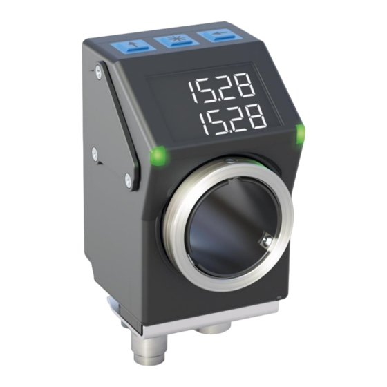
Absolute / elektronische positionsanzeige
Vorschau ausblenden
Andere Handbücher für AP05:
- Benutzerhandbuch (89 Seiten) ,
- Originalmontageanleitung (44 Seiten) ,
- Zusatz zur originalmontageanleitung (40 Seiten)

Verwandte Anleitungen für Siko AP05


Inhaltszusammenfassung für Siko AP05
- Seite 1 AP05 Absolute / elektronische Positionsanzeige Deutsch Originalmontageanleitung Seite 2 Absolute / Electronic Position Indicator English Translation of the Original Installation Instructions page 20 316/18...
-
Seite 2: Inhaltsverzeichnis
6.4 Störung nach Batteriewechsel 7 Transport, Lagerung, Wartung und Entsorgung 8 Zubehör Anschluss-Stecker 8.1 Gegenstecker M8 gerade inkl. Kabel 8.2 Gegenstecker M8 gerade 8.3 Gegenstecker M8 BUS-Abschluss 9 Technische Daten AP05 · Datum 25.09.2018 · Art. Nr. 88847 · Änd. Stand 316/18... -
Seite 3: Dokumentation
Sicherheitshinweise bestehen aus dem Signalzeichen und einem Signal- wort. Gefahrenklassen Unmittelbare Gefährdungen, die zu schweren irreversiblen Körperverlet- GEFAHR zungen mit Todesfolge, Sachschäden oder ungeplanten Gerätereaktionen führen können, sofern Sie die gegebenen Anweisungen missachten. AP05 · Datum 25.09.2018 · Art. Nr. 88847 · Änd. Stand 316/18... -
Seite 4: Zielgruppe
Automatisierungstechnik vertraut sind; • als Inbetriebnahme- und Monatagepersonal berechtigt sind, Strom- kreise und Geräte/Systeme gemäß den Standards der Sicherheitstech- nik in Betrieb zu nehmen, zu erden und zu kennzeichnen. AP05 · Datum 25.09.2018 · Art. Nr. 88847 · Änd. Stand 316/18... -
Seite 5: Grundlegende Sicherheitshinweise
Herstellerbezeichnung eines geeigneten Drehmoment- schlüssels auf Anfrage erhältlich. Anzugsmoment: 0.4 Nm ` Drehmoment/Kräfte nicht über Gehäuse des Gegensteckers oder über das Kabel in das Gerät übertragen. Nur Befestigungsmutter des Gegen- steckers anziehen. AP05 · Datum 25.09.2018 · Art. Nr. 88847 · Änd. Stand 316/18... -
Seite 6: Mechanische Montage
` Positionsanzeige nicht selbst öffnen (Ausnahme siehe Kapitel 6). ` Schläge auf das Gerät vermeiden. ` Keinerlei Veränderung am Gerät vornehmen. Verlust der Schutzart ACHTUNG Bei Betrieb mit offenem Anschluss geht die Schutzart verloren. AP05 · Datum 25.09.2018 · Art. Nr. 88847 · Änd. Stand 316/18... - Seite 7 ø10 (Form B) +0.8 Maß L1 22 Maß øD ø20 (Spielpassung) Tab. 1: Einbaumaße Abb. 1: Einbaumaße Dichtungsplatte Drehmomentstütze Kundenwelle Gewindestift Abb. 2: Montage Abb. 3: Anzugsmoment Gewindestift AP05 · Datum 25.09.2018 · Art. Nr. 88847 · Änd. Stand 316/18...
-
Seite 8: Elektrische Installation
Daher ist darauf zu achten, dass der Anschluss der Positi- Abb. 6). Dadurch onsanzeige über den Anschluss "Bus EIN" erfolgt (siehe sind die spannungsführenden Kontakte an "Bus AUS" durch die Buchse geschützt (zur IP-Schutzart siehe Kapitel 4.1). AP05 · Datum 25.09.2018 · Art. Nr. 88847 · Änd. Stand 316/18... - Seite 9 400 m 19.2 kbit/s 1200 m Anschlussschema CAN Für die Funktion des Feldbusses ist an beiden Busenden je ein Abschluss- widerstand notwendig (120 Ohm). Dieser muss zwischen CANH und CANL eingesetzt werden. AP05 · Datum 25.09.2018 · Art. Nr. 88847 · Änd. Stand 316/18...
- Seite 10 Zubehör Kabelverlängerungen, Gegenstecker und BUS-Abschlusswider- stand siehe Kapitel 8. Belegung Bus-Aus Bus-Ein DÜB/CANL DÜA/CANH Ansichtseite = Steckseite Bus EIN Bus AUS PE Anschluss Abb. 6: Anschlussbelegung Litzenquerschnitt Leitungen 0.14 ... 0.5 mm². AP05 · Datum 25.09.2018 · Art. Nr. 88847 · Änd. Stand 316/18...
-
Seite 11: Inbetriebnahme
2. Zeile der Sollwert dargestellt. Bei kritischem Batte- riezustand blinkt das Sonderzeichen , bei leerer Batterie leuchtet dauerhaft. Bei eingeschaltetem Kettenmaß wird das Kettenmaß- symbol eingeblendet. AP05 · Datum 25.09.2018 · Art. Nr. 88847 · Änd. Stand 316/18... - Seite 12 LED gibt die Richtung an, in welche die Welle ver- dreht werden muss, um den Sollwert zu erreichen. beide LED Aktueller Positionswert befindet sich innerhalb des programmierten Positionsfensters. AP05 · Datum 25.09.2018 · Art. Nr. 88847 · Änd. Stand 316/18...
- Seite 13 2. Kalibrierung (Reset) durchführen (siehe Kapitel 5: Anzeige und Bedientasten) => Positionswert = 0 + Kalibrierwert + Offsetwert Eine Kalibrierung ist aufgrund des absoluten Messsystems nur einmal bei der Inbetriebnahme erforderlich. AP05 · Datum 25.09.2018 · Art. Nr. 88847 · Änd. Stand 316/18...
-
Seite 14: Batteriewechsel
Ausfall Positionsanzeige VORSICHT Unsachgemäße Montage führt zum Verlust der Schutzart. ` Schrauben gleichmäßig anziehen bis Batterieeinheit vollstän- dig auf Anschlag mit Gehäuse ist. ` Korrekte Lage des O-Ringes überprüfen. AP05 · Datum 25.09.2018 · Art. Nr. 88847 · Änd. Stand 316/18... -
Seite 15: Störung Nach Batteriewechsel
` Unzureichende Kontaktierung, Kapitel wiederholen. ` Positionsanzeige von der Versorgungsspannung trennen. Bei erneu- tem Anlegen der Versorgungsspannung wird die Batterieanzeige initi- alisiert und aktualisiert. Kalibrierfahrt nach Benutzerhandbuch vor- nehmen. AP05 · Datum 25.09.2018 · Art. Nr. 88847 · Änd. Stand 316/18... -
Seite 16: Transport, Lagerung, Wartung Und Entsorgung
Batterien recycelt werden. 8 Zubehör Anschluss-Stecker (nicht im Lieferumfang enthalten) 8.1 Gegenstecker M8 gerade inkl. Kabel • Zubehör SIKO Art. Nr. "KV04S1" (Stift/Buchse 4 pol. Bus EIN/Bus AUS). AP05 · Datum 25.09.2018 · Art. Nr. 88847 · Änd. Stand 316/18... -
Seite 17: Gegenstecker M8 Gerade
Bei mehreren Positionsanzeigen an einem Bus: Abschlussstecker am letz- ten Busteilnehmer an Bus AUS anschließen (siehe Kapitel 4.2). Bei einer Positionsanzeige: Abschlussstecker an Bus AUS anschließen (siehe Kapitel 4.2). AP05 · Datum 25.09.2018 · Art. Nr. 88847 · Änd. Stand 316/18... -
Seite 18: Technische Daten
Systemdaten Ergänzung Abtastung magnetisch Auflösung 720 Inkremente/Umdrehung Anzeigewert/Umdrehung frei parametrierbar Messbereich ≤932067 Umdrehung(en) Umgebungsbedingungen Ergänzung Umgebungstemperatur 0 … 60 °C Lagertemperatur -20 … 80 °C relative Luftfeuchtigkeit Betauung nicht zulässig AP05 · Datum 25.09.2018 · Art. Nr. 88847 · Änd. Stand 316/18... - Seite 19 Zustand, bei montiertem Gegen- stecker Schockfestigkeit ≤500 m/s , 11 ms EN 60068-2-27, Halbsinus, 3 Achsen (+/-), je 3 Schocks Vibrationsfestigkeit ≤100 m/s , 10 … 2000 Hz EN 60068-2-6, 3 Achsen, je 10 Zyklen AP05 · Datum 25.09.2018 · Art. Nr. 88847 · Änd. Stand 316/18...
- Seite 38 AP05...
- Seite 39 AP05...
- Seite 40 SIKO GmbH Weihermattenweg 2 79256 Buchenbach Telefon/Phone + 49 7661 394-0 Telefax/Fax + 49 7661 394-388 E-Mail info@siko.de Internet www.siko-global.com Service support@siko.de...