Seite 1
S700 Safety Guide Edition: September 2015 Valid for HWR 02.20 Deutsch English Français Italiano Русский Original Language is German. All other content is translated from the genuine German content. Keep all manuals as a product component during the life span of the product. Pass all manuals to future users and owners of the product. Bewahren Sie alle Anleitungen während der gesamten Nutzungs- Conservare il manuale per l’intera durata del prodotto.
Seite 2
Translation of the original manual, printed in the Federal Republic of Germany All rights reserved. No part of this work may be reproduced in any form (by photocopying, microfilm or any other method) or stored, processed, copied or distributed by electronic means without the written permission of Kollmorgen Europe GmbH.
1.1 Allgemeines Dieses Handbuch beschreibt die digitalen Servoverstärker S700 (Standard Version, 1,5 A bis 72 A Nennstrom). Vollständige Informationen finden Sie in der Betriebsanleitung und weiteren Kollmorgen Doku- menten: Betriebsanleitung (PDF Format): Das Handbuch enthält Hinweise zur Installation und Konfiguration des Servoverstärkers.
Dieses Symbol weist auf wichtige Informationen hin. Warnung vor einer Gefahr (allgemein). Die Art der Gefahr wird durch den nebenstehenden Warntext spezifiziert. Warnung vor gefährlicher elektrischer Spannung und deren Wirkung. Warnung vor heißer Oberfläche. Warnung vor hängender Last. Kollmorgen | September 2015...
Prüfen Sie die Hardware-Revisionsnummer des Produkts (siehe Typenschild). Diese Revi- sionsnummer muss mit der Hardware-Revisionsnummer auf dem Deckblatt der Betriebs- anleitung übereinstimmen. Wenn die Nummern nicht übereinstimmen, besuchen Sie das Tech-WIKI (http://www.wiki-kollmorgen.eu). Im Bereich "Download" finden Sie alle Hand- buchversionen mit Bezug zur Hardware Revisions-Nummer. Technische Daten beachten Halten Sie die technischen Daten und die Angaben zu den Anschlussbedingungen (Typen- schild und Dokumentation) ein.
Seite 8
Isolierung (gem. EN 61800-5-1) gegenüber Systemkomponenten mit Leistungsspannung versehen sein, entsprechend der geforderten Prüfspannung der Appli- kation. Alle Kollmorgen Komponenten entsprechen diesen Anforderungen. Geräte nicht verändern Veränderung an den Servoverstärker ohne Erlaubnis des Herstellers sind nicht zulässig. Öff- nen der Geräte bedeutet Verlust der Gewährleistung und alle Zertifikate der Geräte verlieren...
SIL3/PLe wird bei zweikanaligem Ansteuern von STO1-ENABLE und STO2-ENABLE nur erreicht, wenn das sichere Schalten der Impulssperre periodisch getestet wird. Bei Verwendung der Safety Karte S1-2 (S3) bzw S2-2 (S4) beachten Sie die Bedie- nungsanleitungen der Sicherheitskarten. Kollmorgen | September 2015...
Servoverstärker berühren. Vermeiden Sie es, hoch isolierende Stoffe zu berühren (Kunst- fasern, Plastikfolie usw.). Legen Sie den Servoverstärker auf eine leitfähige Oberfläche. 1.2.5 Verpackung Die S700 Verpackung besteht aus einem recyclebaren Karton mit Einlagen. Maße S701...S712: (HxBxT) 125x415x350 mm Maße S724: (HxBxT) 155x415x350 mm Maße S748/S772: (HxBxT) 390x600x400 mm Kennzeichnung: Geräte-Typenschild außen am Karton...
Sie ihn in der Originalverpackung an den Hersteller. Gemäß den WEEE-2002/96/EG-Richtlinien u.ä. nimmt der Hersteller Altgeräte und Zubehör zur fachgerechten Entsorgung zurück. Die Transportkosten muss der Versender tragen. Setzen Sie sich mit Kollmorgen in Verbindung und klären Sie die logistische Abwicklung. Kollmorgen | September 2015...
S700 Safety Guide | 1 Deutsch 1.3 Technische Beschreibung und Daten 1.3.1 Die digitalen Servoverstärker der Familie S700 Typenschlüssel Benutzen Sie den Typenschlüssel zur Produktidentifizierung, jedoch nicht für den Bestell- prozess, da nicht immer alle Merkmal-Kombinationen technisch möglich sind. Kollmorgen | September 2015...
Die SubD-Gegenstecker gehören nicht zum Lieferumfang! Zubehör (muss bei Bedarf separat bestellt werden, siehe Zubehörhandbuch): S748...772: Netzdrossel 3L erforderlich bei Netzunsymmetrie >3%. S701...724: Motordrossel 3YL erforderlich bei Leitungslänge über 25 m Motorleitung und Feedbackleitung Externer Bremswiderstand Kommunikationsleitung zum PC oder Y-Adapter für das Parametrieren von bis zu 6 Ser- voverstärkern an einem PC...
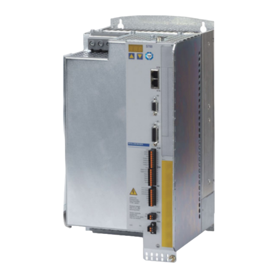
S701...S724: 1x110V-10% …1x230V+10%, 50/60 Hz 3x110V-10% …3x480V+10%, 50/60 Hz S748...S772: 3x208V-10% ...3x 480V+10%, 50/60 Hz Hilfsspannungsversorgung 24 V DC (-0% +15%), S701...724: 3A, S748...772: 5A (mit Bremse) Spannungsverlust beachten ! Umgebungstemperatur im 0 bis +40°C bei Nenndaten Betrieb +40 bis +55°C mit Leistungsrücknahme 2,5% / K Feuchtigkeit im Betrieb Rel.
Inbetriebnahmesoftware gestartet werden. Die Bedienung über ASCII Kommandos ist im Produkt-WIKI auf Seite "Speicherkarte" beschrieben. Die Speicherkarte darf nur bei ausgeschaltetem Servoverstärker gesteckt oder entfernt wer- den. Bei Einsatz eines Absolutwertgebers muss nach Einlesen der Parameter in ein neues Gerät eine Referenzfahrt durchgeführt werden. Kollmorgen | September 2015...
Wird die Funktion STO in einer Anwendung nicht benötigt, so müssen die Eingänge STO1- ENABLE und STO2-Enable direkt mit +24VDC verbunden werden. Der Servoverstärker ist nun nicht mehr als Sicherheitsbauteil im Sinne der Maschinenrichtlinie zu betrachten. Kollmorgen | September 2015...
Seite 21
Eine Beschreibung der Testsequenz finden Sie in der Betriebsanleitung. Technische Daten STO1-Enable und STO2-Enable Daten Eingangsspannung 20V..30V Eingangsstrom 33mA – 40mA (Ieff) Spitzenstrom 100mA (Is) Reaktionszeit (fallende Flanke am STOx-Eingang bis zur STO1: 1ms Unterbechung der Energiezufuhr zum Motor) STO2: 2ms Kollmorgen | September 2015...
Seite 22
S700 Safety Guide | 1 Deutsch Anschlussbelegung S701...S724 Zum Erreichen von SIL CL3 / PLe wird der Schaltzustand der Impulssperre (Status) mit dem ASCII-Befehl OxMODE 70 auf einen der digitalen Ausgänge DIGITAL-OUT1 oder 2 (X3A/6 oder X3A/7) des S700 gelegt. Kollmorgen | September 2015...
Seite 23
S700 Safety Guide | 1 Deutsch Anschlussbelegung S748...S772 Zum Erreichen von SIL CL 3 / PLe wird der Schaltzustand der Impulssperre in der Sicher- heitssteuerung periodisch getestet. Kollmorgen | September 2015...
Seite 24
S700 Safety Guide | 1 Deutsch Signaldiagramm Das Diagramm zeigt, wie die Funktion STO genutzt werden sollte, damit ein sicherer Halt des Antriebs und fehlerfreier Betrieb des Servoverstärkers gewährleistet ist. Kollmorgen | September 2015...
Beachten Sie die erforderlichen Freiräume ober- und unterhalb der Ser- voverstärker(➜ # 196). Montage Montieren Sie Servoverstärker und Netzteil nahe beieinander auf der leitenden, geerdeten Montageplatte im Schaltschrank. Erdung, EMV-gerechte Abschirmung und Erdung siehe Betriebsanleitung. Abschirmung Erden Sie Montageplatte, Motorgehäuse und CNC-GND der Steue- rung. Kollmorgen | September 2015...
Verdrahten Sie den BTB/RTO-Kontakt in Reihe zur Not-Halt-Schaltung der Anlage. Die Not-Halt Schaltung muss das Netzschütz betätigen. Die Setup-Software kann verwendet werden, um die Einstellungen des Servoverstärkers zu ändern. Jede weitere Veränderung führt zum Erlöschen der Garantie. Kollmorgen | September 2015...
Servoverstärker etwa 30min einphasig mit der kleinsten zulässigen Versorgungsspan- nung an den Klemmen L1 / L2. Dadurch werden die Kondensatoren neu formiert. Das Anpassen von Parametern und die Auswirkungen auf das Regelverhalten wird in der Online Hilfe der Inbetriebnahmesoftware beschrieben. Kollmorgen | September 2015...
: ein Menüpunkt nach unten, Zahl um eins verkleinern zweimal schnell hintereinander drücken : Zahl um zehn verkleinern rechte Taste gedrückt halten und linke Taste zusätzlich drücken : zur Zahleneingabe, Return-Funktion Name 1.6.2.1 Statusanzeige 1.6.2.2 Standard Menü Kollmorgen | September 2015...
CD-Laufwerksbuchstabe) ein. Klicken Sie OK und gehen dann wie oben beschrie- ben vor. Anschluss an serielle Schnittstelle des PC Schließen Sie die Übertragungsleitung an eine serielle Schnittstelle Ihres PC und an die seri- elle Schnittstelle (X6) des S700 an (➜ # 204). Kollmorgen | September 2015...
Seite 31
S700 Safety Guide | 1 Deutsch 1.6.3.3 Minimale Verdrahtung für den Schnelltest S701...S724 ohne Last Diese Verdrahtung erfüllt keinerlei Anforderungen an die Sicherheit oder Funktionstüchtigkeit Ihrer Anwendung. Sie zeigt lediglich die für den Schnelltest erforderliche Mindestverdrahtung. Kollmorgen | September 2015...
Seite 32
S700 Safety Guide | 1 Deutsch 1.6.3.4 Minimale Verdrahtung für den Schnelltest S748...S772 ohne Last Diese Verdrahtung erfüllt keinerlei Anforderungen an die Sicherheit oder Funktionstüchtigkeit Ihrer Anwendung. Sie zeigt lediglich die für den Schnelltest erforderliche Mindestverdrahtung. Kollmorgen | September 2015...
Seite 33
Nach Bestätigen der Fehlermeldung schaltet die Software in den Offline-Modus um. Dies erfordert die manuelle Auswahl des Servoverstärkers. Brechen Sie die Auswahl ab indem Sie das Auswahlfenster schließen. Suchen und beseitigen Sie den Fehler, der die Kom- munikation verhindert. Starten Sie die Software erneut im Online-Modus. Kollmorgen | September 2015...
Sie Parameter geändert haben Reset (Kaltstart), wird benötigt, wenn Sie wichtige Basis-Parameter geändert haben Betriebsart, verwenden Sie "0:Drehzahl Digital" für den Schnelltest. Statusleiste Das grüne Online Symbol zeigt an, dass die Kommunkation arbeitet. Kollmorgen | September 2015...
"F19" wählen. F19" führt zum Abschalten der Endstufe, "n05" wird als Meldung behandelt. Name: Sie können dem Servoverstärker einen Namen (max. 8 Zeichen) zuweisen. Dies ver- einfacht die Identifikation des Antriebs im System. Beim Booten Software-Enable setzen:Diese Option für den Schnelltest nicht anwählen! Klicken Sie auf Weiter. Kollmorgen | September 2015...
Wenn ein Getriebe am Motor angeflanscht ist, können Sie bei den in Frage kommenden Anwendungen zusätzlich die Getriebedaten eingeben, entweder die Anzahl der Zähne oder das Verhältnis der Umdrehungen. Klicken Sie anschließend auf die Schaltfläche "Umrechnungsfaktoren berechnen und schlie- ßen". Klicken Sie auf WEITER. Kollmorgen | September 2015...
Seite 37
Bremse: Soll der Verstärker eine Bremse ansteuern, Feld Haltebremse auf MIT ändern. Regler-Parameter: Wenn Sie das Massenverhältnis Last/Motor kennen (0 bedeutet keine Last), geben Sie diese Zahl ein und wählen Sie die gewünschte Steifigkeit der Regelung. Wenn das Verhältnis nicht bekannt ist, wählen Sie "Einst. nicht ändern". Kollmorgen | September 2015...
Schalten Sie die Leistungsversorgung des Antriebs ein. STOx-Enable: S701...S724: +24 V an STO1-Enable [X4B/6] und an STO2-Enable [X4A/3] S748...S772: +24 V an STO1-Enable [X4/5] und an STO2-Enable [X4/7] Hardware-Enable: +24 V an Eingang Enable [X3A/1]. Wenn STO-Enable fehlt beim Hard-...
ARLPF / ARHPF vergrößern ARLP2 zu klein ARLP2 vergrößern Achse driftet bei Offset bei analoger Sollwertvorgabe SW-Offset (Analog I/O) abgleichen Sollwert=0V nicht korrekt abgeglichen AGND nicht mit CNC-GND der Steue- AGND und CNC-GND verbinden rung verbunden Kollmorgen | September 2015...
Seite 40
S700 Safety Guide | 1 Deutsch --- / --- Kollmorgen | September 2015...
Seite 41
2.2.9 Repair and Disposal 2.3 Technical description and data 2.3.1 The S700 Family of digital servo amplifiers 2.3.2 Package Supplied 2.3.3 Motion system with S701...S724 2.3.4 Motion system with S748...S772 2.3.5 Ambient Conditions, Ventilation, and Mounting Position 2.3.6 Recommended Tightening Torques 2.3.7 Technical Data 110 / 230 V...
This manual describes the digital servo amplifiers of the S700 (standard version, 1.5 to 72 A nominal current). For full information refer to the Instructions Manual and additional Kollmorgen documents: Instructions Manual (PDF format): This manual provides instructions for installation and servo amplifier setup.
This symbol indicates important notes. Warning of a danger (general). The type of danger is spe- cified by the text next to the symbol. Warning of danger from electricity and its effects. Warning of hot surfaces. Warning of suspended loads. Kollmorgen | September 2015...
Safe limited position Safe limited speed Safe operating stop SRAM Static RAM Safe stop Safe operational stop Synchronous serial interface Safe speed range Safe Torque Off V AC AC voltage V DC DC voltage Verein deutscher Elektrotechniker Kollmorgen | September 2015...
Hardware Revision Number on the cover page of the manual. If the num- bers do not match up, visit the Tech-WIKI ( (http://www.wiki-kollmorgen.eu). The 'Download' section contains the various manual versions based on the hardware version number.
Seite 46
Thermal sensors, motor holding brakes and feedback systems built into the connected motor must have reinforced insulation (according to IEC61800-5-1) against system components with power voltage, according to the required application test voltage. All Kollmorgen com- ponents meet these requirements.
To achieve PL e or SIL CL3, the safe switching of the pulse inhibitor must be tested peri- odically by analyzing the feedback signal from the safety control. Observe the user documentation for safety cards S1-2(S3) / S2-2(S4) when you use a safety expansion card. Kollmorgen | September 2015...
Labeling : nameplate outside at the box 2.2.6 Storage Storage only in the manufacturer’s original recyclable packaging Max. stacking height S701...S724: 8 cartons Max. stacking height S748...S772: 3 cartons Storage temperature: -25 to +55°C, max. rate of change 20K/h, class 1K4 acc. to EN61800-2 Storage humidity: 5 ...
In accordance with the WEEE-2002/96/EC-Guidelines and similar, the manufacturer accepts returns of old devices and accessories for professional disposal. Transport costs are the responsibility of the sender. Contact Kollmorgen and clarify the logistics. Kollmorgen | September 2015...
2.3 Technical description and data 2.3.1 The S700 Family of digital servo amplifiers Part Number Scheme Use the part number scheme for product identification only, not for the order process, because not all combinations of features are possible, always. Kollmorgen | September 2015...
Accessories: (must be ordered separately; description see accessories manual) S748...772: Mains choke 3L required, if mains voltage is more than 3% asymmetrical. S701...724 : Motor choke 3YL required, if cable length > 25m Motor cable and feedback cable External brake resistor...
1x110V-10% …1x230V+10%, 50/60 Hz 3x110V-10% …3x480V+10%, 50/60 Hz S748...S772: 3x208V-10% ...3x 480V+10%, 50/60 Hz Aux. power supply 24 V DC (-0% +15%), S701...724: 3A, S748...772: 5A (with brake) Check voltage drop! Surrounding temperature in 0 to +40°C (32 to 104°F) at rated data operation +40 to +55°C (113 to 131°F) with power derating 2.5% / K...
" "Memory Card"". Always switch off the servo amplifier before inserting or removing the memory card. If an absolute encoder is used, homing must be carried out before the parameters are loaded into a new device. Kollmorgen | September 2015...
If the STO function is not needed in the application, then the inputs STO1-ENABLE and STO2-Enable must be connected directly with +24VDC. The servo amplifier cannot be used as a safety component referring to the EC Machine Directive now. Kollmorgen | September 2015...
Seite 59
Technical data STO1-Enable and STO2-Enable Data Input voltage 20V..30V Input current 33mA – 40mA (Ieff) Peak current 100mA (Is) Response time (falling edge at STO input STO1: 1ms until energy supply to motor is interrupted) STO2: 2ms Kollmorgen | September 2015...
Seite 60
To achieve PLe / SIL CL3, the safe switching of the pulse inhibitor must be tested peri- odically by analyzing the status signal from a safety control. Therefore the status must be linked to one of the digital outputs DIGITAL-OUT1 or 2 (X3A/6 or X3A/7) with the ASCII com- mand OxMODE70. Kollmorgen | September 2015...
Seite 61
S700 Safety Guide | 2 English Pinout S748...S772 To achieve PLe / SIL CL3, the safe switching of the pulse inhibitor must be tested peri- odically by analyzing the status signal from a safety control. Kollmorgen | September 2015...
Seite 62
S700 Safety Guide | 2 English Signal diagram The diagram shows how to use STO function to ensure a safe stop of the drive and error free operation of the servo amplifier. Kollmorgen | September 2015...
Assemble the servo amplifier and power supply, filter and choke close together on the conductive, grounded mounting plate in the cabinet. Grounding EMC-compliant (EMI) shielding and grounding see Instructions Manual. Shielding Earth (ground) the mounting plate, motor housing and CNC-GND of the controls. Kollmorgen | September 2015...
Wire the BTB/RTO contact in series into the emergency stop circuit of the install- ation. The emergency stop circuit must operate the supply contactor. It is permissible to use the setup software to alter the settings of the servo amplifier. Any other alterations will invalidate the warranty. Kollmorgen | September 2015...
Connect the encoder emulation, if required Connect the expansion card Connect the motor cables, connect shielding at both ends. S701-724: use motor chokes (3YL) for lead lengths >25m. Connect motor-holding brake, connect shielding at both ends. Connect the external brake resistor (with fusing) if required Connect aux.
Supply the servo amplifier for about 30 minutes from single-phase 230VAC to the terminals L1 / L2. This will re-form the capacitors. The adaptation of parameters and the effects on the control loop behavior are described in the Online Help of the setup software. Kollmorgen | September 2015...
: go down one menu item, decrease number by one press twice in rapid succession : decrease number by ten press and hold right key, then press left key as well : enter a number, return function name 2.6.2.1 Status display 2.6.2.2 Standard Menu Kollmorgen | September 2015...
(x = correct CD drive letter). Click OK and proceed as described above. Connection to the serial interface of the PC Connect the interface cable to a serial interface on your PC and the PC interface (X6) of the S700 (➜ # 204). Kollmorgen | September 2015...
Seite 69
S700 Safety Guide | 2 English 2.6.3.3 Minimum Wiring for Drive Test S701...S724 without load This wiring does not fulfill any requirements to safety or functionality of your application, it just shows the required wiring for drive testing without load.
Seite 70
S700 Safety Guide | 2 English 2.6.3.4 Minimum Wiring for Drive Test S748...S772 without load This wiring does not fulfill any requirements to safety or functionality of your application, it just shows the required wiring for drive testing without load. Kollmorgen | September 2015...
Seite 71
Quit the error message. The software starts in the offline mode now, that requires the manual selection of the amplifier's type. Quit this selection by closing the window. Fix the com- munication problem. Restart the software in Online mode. Kollmorgen | September 2015...
Seite 72
Save to EEPROM, required if you changed parameters. Reset, required if you changed configuration parameters. Operation Mode, use "0: Digital Velocity" mode for drive test- ing. Status Bar The status bar shows a green Online symbol, indicating that the communication works. Kollmorgen | September 2015...
Name: You can enter a name for the servo amplifier (up to 8 characters). This simplifies the drive identification in the system. Set Software Enable on Bootup:Don't select this option for the quick test. Click NEXT. Kollmorgen | September 2015...
Seite 74
If a gearhead is flange-mounted on the motor, you must also enter the gearhead data (either the number of teeth or the ratio of the revolutions). Then click the “Calculate conversion factors and return” button. Click NEXT. Kollmorgen | September 2015...
Seite 75
Calculated quick tuning: If you know the Load-to-motor inertia ratio (0 is for no load), enter the number here and select the desired servo performance. If you don't know the inertia ratio, select "Do not tune". Click FINISH. Kollmorgen | September 2015...
Seite 76
Switch on the power supply for the drive. STOx-Enable: S701...S724: apply +24 V to STO1-Enable [X4B/6] and to STO2-Enable [X4A/3] S748...S772: apply +24 V to STO1-Enable [X4/5] and to STO2-Enable [X4/7] Hardware-Enable:apply +24 V to input Enable [X3A/1]. If STO-Enable is missed or the...
ARLP2 too low increase ARLP2 Axis drifts at offset not correctly adjusted for ana- adjust setpoint-offset (analog I/O) setpoint = 0V log setpoint provision AGND not joined to the CNC-GND of join AGND and CNC-GND the controls Kollmorgen | September 2015...
Seite 78
S700 Safety Guide | 2 English --- / --- Kollmorgen | September 2015...
Seite 79
3.3 Déscription technique et donnée techniques 3.3.1 Les variateurs numériques de la famille S700 3.3.2 Etendue de la livraison 3.3.3 Système d'entraînement avec S701...S724 3.3.4 Système d'entraînement avec S748...S772 3.3.5 Conditions ambiantes, aération, position de montage 3.3.6 Couples de serrage recommendée 3.3.7 Donnée techniques 110 / 230 V...
Reader ) en plusieurs versions linguistiques. Vous pouvez imprimer la documentation sur n’importe quelle imprimante du commerce. Plus d’information peut être trouvée dans le “Product WIKI” (www.wiki-kollmorgen.eu). 3.1.1 Remarques sur la version imprimée (version papier) Chaque produit est fourni avec une version imprimée du Guide.
Ce symbole indique des remarques importantes. Avertissement de danger (en général). Le type de dan- ger est indiquée par le texte d'avertissement ci-contre. Avertissement de tension électrique dangereuse et l'ef- fet. Avertissement des surfaces chaudes. Avertissement d'une charge suspendue. Kollmorgen | September 2015...
Mise hors tension sûre Arrêt de fonctionnement sûr Interface sérielle synchrone Plage de vitesse sûre Fonction de suppression sûre du couple (Safe Torque Off) V AC Tension alternative V DC Tension continue Association des Electrotechniciens allemands Kollmorgen | September 2015...
Vérifiez le numéro de version matérielle du produit (voir plaque signalétique). Ce numéro doit correspondre aux indications figurant sur la page de titre du présent manuel. Si les numéros ne correspondent pas, consultez notre “Tech-WIKI” (http://www.wiki-kollmorgen.eu). Dans la rubrique "Download", vous trouverez toutes les versions du manuel en rapport avec le numéro de révision du matériel.
Seite 84
être pourvus d’une isolation renforcée (selon la norme EN 61800- 5-1) par rapport aux composants systèmes dotés d’une tension d’alimentation, confor- mément à la tension d’essai requise de l’application. Tous les composants de Kollmorgen satisfont à ces exigences.
SIL3/PLe n’est atteint lors du pilotage bicanal des entrées STO1-ENABLE et STO2- ENABLE que lorsqu’une commutation sûre du blocage d’impulsion est testée pério- diquement. En cas d’utilisation de la carte “Safety” S1-2 (S3) ou S2-2 (S4), respectez le mode d’em- ploi des cartes de sécurité. Kollmorgen | September 2015...
Conformément à la directive WEEE-2002/96/CE ou réglementation similaire, le fabricant accepte le retour d'appareils ou d'accessoires usagés pour une mise au rebut pro- fessionnelle. Les frais de transport incombent à l'expéditeur. Contactez Kollmorgen et de clarifier la logistique. Kollmorgen | September 2015...
Clé de type Utilisez le code de type uniquement à des fins d'identification des produits. Ne pas utiliser le code type pour les bons de commande, comme toutes les combinaisons de caractéristiques ne sont pas techniquement possible. Kollmorgen | September 2015...
Accessoires: (à commander en sus si nécessaire; voir le manuel des accessoires): S748...S772: Inductance réseau 3L nécessaire en cas d'asymétries réseau > 3% S701...S724: Bobine de choc moteur 3YL pour longueurs de câble de plus de 25 m. Câble moteur et câble de rétroaction Résistance ballast externe...
1x110V-10% …1x230V+10%, 50/60 Hz 3x110V-10% …3x480V+10%, 50/60 Hz S748...S772: 3x208V-10% ...3x 480V+10%, 50/60 Hz Alimentation en auxiliaire 24 V DC (-0% +15%), S701...724: 3A, S748...772: 5A, (avec frein) Tenir compte de perte de tension! Température ambiante en 0 à +40°C à données nominales service +40 à...
La carte mémoire ne peut être enfichée ou retirée du variateur S700 que s’il est déconnecté. En cas d’utilisation d’un codeur absolu, un trajet de référence doit être effectué après la lec- ture des paramètres dans un nouvel appareil. Kollmorgen | September 2015...
Si la fonction n’est plus nécessaire dans une application, les entrées STO1-ENABLE et STO2-Enable doit être directement raccordée à l’alimentation +24 V DC. Le variateur ne peut alors plus être considéré comme composant de sécurité au sens de la directive Machine. Kollmorgen | September 2015...
Tension d’entrée 20V..30V Courant d’entrée 33mA – 40mA (Ieff) Courant de crête 100mA (Is) Temps de réaction (front descendant sur l’en- trée STOx jusqu’à pour interruption de l’ali- STO1: 1ms mentation en énergie du moteur) STO2: 2ms Kollmorgen | September 2015...
Seite 98
Pour atteindre SIL CL3 / PLe, l’état de commutation du blocage d’impulsions (état) est défini sur l’une des sorties numériques DIGITAL-OUT1 ou 2 (X3A/6 ou X3A/7) du variateur S700à l’aide de la commande ASCII OxMODE 70. Kollmorgen | September 2015...
Seite 99
S700 Safety Guide | 3 Français Brochage S748...S772 Pour atteindre SIL CL 3 / Ple, l'état de commutation du blocage d'impulsions dans la com- mande de sécurité est testé périodiquement. Kollmorgen | September 2015...
Seite 100
S700 Safety Guide | 3 Français Schéma de la fonction Le schéma montre comment la fonction STO doit être utilisée afin de garantir un arrêt en toute sécurité de l’entraînement et un fonctionnement sans problème du variateur. Kollmorgen | September 2015...
Mise à la terre, Blindage et mise à la terre conformes à la CEM voir Manuel d'Ins- blindage tructions. Mettre à la terre la plaque de montage, le carter du moteur et la CNC-GND de l'API. Kollmorgen | September 2015...
Le circuit d'arrêt d'urgence doit utiliser le contacteur d'alimentation. Des modifications du réglage des variateurs au moyen du logiciel setup sont autorisées. Toute autre intervention non autorisée entraîne automatiquement la perte des droits de garan- tie. Kollmorgen | September 2015...
Raccorder la carte d'expansion. Raccorder les câbles moteur, posez les blindages des deux côtés. S701-724: En cas d'une longueur de câble > 25 mm, utiliser des bobines de choc moteur (3YL). Raccorder le frein d'arrêt du moteur, posez le blindage des deux côtés.
230 V CA sur les bornes L1 / L2. Ceci aura pour effet de reformer les condensateurs. L'adaptation de paramètres et les effets sur la régulation sont décrits dans Online Help de la logiciel de mise en service. Kollmorgen | September 2015...
10 du chiffre maintenir la touche de droite enfoncée puis appuyer en plus sur la touche de gauche : pour l'entrée numérique, fonction Return (Entrée) 3.6.2.1 Affichage d'état 3.6.2.2 Menu Standard Kollmorgen | September 2015...
CD). Cliquez sur OK puis continuez comme décrit plus haut. Raccordement à l'interface sériel du PC Raccordez la ligne de transfert à l'interface sériel de votre PC puis à l'interface PC (X6) du S700 (➜ # 204). Kollmorgen | September 2015...
Seite 107
S700 Safety Guide | 3 Français 3.6.3.3 Câblage minimal pour le test rapide S701...S724 sans charge Ce câblage ne remplit pas d’exigences en matière de sécurité ou efficacité du fonc- tionnement de votre application. Elle ne montre que le câblage minimal nécessaire pour le test rapides.
Seite 108
3.6.3.4 Câblage minimal pour le test rapide S748...S772 sans charge Ce câblage ne remplit pas d’exigences en matière de sécurité ou efficacité du fonc- tionnement de votre application. Elle ne montre que le câblage minimal nécessaire pour le test rapides. Kollmorgen | September 2015...
Seite 109
Après confirmation du message d’erreur, le logiciel passe en mode hors ligne. Ceci exige la sélection manuelle du variateur. Interrompez la sélection en fermant la fenêtre de sélection. Identifiez et corrigez l’erreur empêchant la communication. Redémarrez le logiciel en mode en ligne. Kollmorgen | September 2015...
Seite 110
Reset (démarrage à froid), est nécessaire lorsque des para- mètres de base importants ont été modifiés Type de fonctionnement, utilisez « 0 : vitesse numérique » pour le test rapide. Barre d’état L’icône verte Online (en ligne) indique que la communication est active. Kollmorgen | September 2015...
Name: vous pouvez attribuer un nom au variateur (max. 8 caractères). Il simplifiera l’iden- tification de l’entraînement dans le système. Set Software Enable on Bootup:ne sélectionnez pas cette option pour le test rapide ! Cliquez sur NEXT (Suivant). Kollmorgen | September 2015...
Seite 112
Si un réducteur est bridé sur un moteur, vous pouvez, pour les applications concernées, éga- lement saisir les données de ce réducteur, soit le nombre de dents ou le rapport de tours. Cliquez ensuite sur le bouton “Calculate conversion factor and return”. Cliquez sur NEXT. Kollmorgen | September 2015...
Seite 113
Calculated quick tuning: Si vous connaissez le rapport de poids charge/moteur (0 = aucune charge), indiquez ce nombre et sélectionnez la pente désirée pour la régulation. Si vous ne connaissez pas le rapport, sélectionnez “Do not tune” (ne pas modifier). Kollmorgen | September 2015...
Seite 114
Respectez les exigences relatives à la “vitesse réduite sûre” pour votre application ! Enclenchez l’alimentation de puissance de l’entraînement. STOx-Enable: S701...S724: +24 V sur STO1-Enable [X4B/6] et sur STO2-Enable [X4A/3] S748...S772: +24 V sur STO1-Enable [X4/5] et sur STO2-Enable [X4/7] Hardware-Enable: +24 V sur l’entrée Enable [X3A/1]. En cas d’absence de STO-Enable pour Hardware Enable, l’affichage de la platine avant indique...
équilibrer l'offset VC (Analog I/O) valeur de consi- définie analogique n'est pas cor- gne=0V rectement équilibré l'AGND n'est pas reliée à la CNC-GND relier l'AGND et la CNC-GND de l'API Kollmorgen | September 2015...
Seite 116
S700 Safety Guide | 3 Français --- / --- Kollmorgen | September 2015...
Seite 117
4.2.9 Riparazione e smaltimento 4.3 Descrizione e dati tecnici 4.3.1 Servoamplificatori digitali della famiglia S700 4.3.2 Dotazione 4.3.3 Sistema di azionamento con S701...S724 4.3.4 Sistema di azionamento con S748...S772 4.3.5 Condizioni ambientali, aerazione, posizione di montaggio 4.3.6 Coppie di serraggio consigliate 4.3.7 Dati tecnici 110 / 230 V...
DIN A5. In caso di difficoltà a leggere il testo nel formato stampato ridotto, è possibile stampare e utilizzare la versione PDF in formato DIN A4 1:1. La versione PDF è memorizzata sul CD-ROM del prodotto. Kollmorgen | September 2015...
Avviso di pericolo (generale). Il tipo di pericolo è specificato nel testo a fianco. Avviso di pericolo dovuto all'elettricità e ai suoi effetti. Avviso di pericolo per la presenza di superfici calde. Avvertimento di un carico sospeso Kollmorgen | September 2015...
Unità di controllo a logica programmabile SRAM RAM statica Arresto sicuro Arresto activa sicuro Interfaccia seriale sincrona Range di velocità sicuro Interfaccia sincrono-seriale Safe Torque Off V AC Tensione alternata V DC Tensione continua Associazione elettrotecnica tedesca Kollmorgen | September 2015...
Questo numero deve corrispondere alle indicazioni riportate sulla copertina del presente manuale. Se i numeri non corrispondono, accedere a Tech-WIKI (http://www.wiki-kollmorgen.eu). Nella sezione “Download” sono presenti tutte le versioni del manuale con riferimento ai numeri di revisione dell’hardware. Rispettare i dati tecnici Osservare i dati tecnici e le indicazioni sulle condizioni di collegamento (targhetta di omologazione e documentazione).
Seite 122
(secondo EN 61800-5-1) nei confronti dei componenti del sistema con tensione di alimentazione, in base alla tensione di prova richiesta dall’applicazione. Tutti i componenti Kollmorgen rispondono a questi requisiti. Non modificare gli apparecchi Non è...
Consideri le documentazioni di utente per le carte di sicurezza S1-2 (S3) e S2-2 (S4) quando usate le funzioni di sicurezza offerte da queste carte di espansione. Kollmorgen | September 2015...
4.2.6 Conservazione solo nell'imballaggio riciclabile originale del produttore: S701...S724: conservare a un'altezza di impilaggio pari o inferiore 8 cartoni S748...S772: conservare a un'altezza di impilaggio pari o inferiore 3 cartoni intervalli di temperatura specifici: da -25 a +55°C, tasso di variazione max. 20 K/ora, categoria 1K4 secondo EN61800-2 intervalli di umidità...
In conformità alle linee guida della direttiva 2002/96/CE (RAEE) e simili, il costruttore accetta la restituzione di vecchi dispositivi ed accessori per uno smaltimento professionale. I costi di trasporto sono a carico del mittente. Contattare Kollmorgen e chiarire la logistica. Kollmorgen | September 2015...
4.3.1 Servoamplificatori digitali della famiglia S700 Schema di numero Utilizzare il codice di tipo esclusivamente a scopo di identificazione del prodotto. Non utilizzare il codice tipo per ordini di acquisto, in quanto non tutte le combinazioni sono dotate sono tecnicamente possibili. Kollmorgen | September 2015...
Accessori: (da ordinare in via supplementare se necessari; per la descrizione vedere il manuale degli accessori) S701...724: Induttanza per motore 3YL per cavi di lunghezza > 25 m S748...772: Bobina delle rete 3L per asimmetria di tensione delle rete > 3%...
Inserire e togliere la scheda di memoria solo quando l’ S700 è spento. Se si impiega un trasduttore assoluto, dopo aver caricato i parametri in un apparecchio nuovo occorre eseguire una corsa al punto di riferimento. Kollmorgen | September 2015...
+24 V DC. In tal modo si esclude il sistema di protezione contro il riavvio accidentale che quindi non può essere utilizzato. Il servoamplificatore non può essere utilizzato come componente di sicurezza riferirsi alla Direttiva Macchine CE. Kollmorgen | September 2015...
STO1-Enable e STO2-Enable Dati Tensione di ingresso 20V..30V Corrente in ingresso 33mA – 40mA (Ieff) Corrente di picco 100mA (Is) Tempo di reazione (fronte in discesa sull'ingresso STO fino STO1: 1ms all'interruzione dell'alimentazione diretta al motore) STO2: 2ms Kollmorgen | September 2015...
Seite 136
S700 Safety Guide | 4 Italiano Schemo collegamenti S701...S724 SIL CL3/PLe richiede il controllo periodico della serratura della fase dell’uscita. Di conseguenza la condizione deve essere collegata ad una delle uscite digitali DIGITAL-OUT1 o a 2 (X3A/6 o X3A/7) con l’ordine OxMODE70 di ASCII.
Seite 137
S700 Safety Guide | 4 Italiano Schemo collegamenti S748...S772 SIL CL3/PLe richiede il controllo periodico lo stato di commutazione di impulsi inibisce nel controllore di sicurezza. Kollmorgen | September 2015...
Seite 138
S700 Safety Guide | 4 Italiano Schema dei segnali (sequenza) Lo schema seguente illustra l'impiego del blocco riavvio STO per un arresto in sicurezza e un funzionamento corretto del servoamplificatore. Kollmorgen | September 2015...
Messa a terra, Schermatura conforme alla direttiva in materia di compatibilità Schermatura elettromagnetica e messa a terra vedere Manuale d'Istruzioni. Collegare a terra piastra di montaggio, carcassa del motore e CNC- GND dell'unità di controllo. Kollmorgen | September 2015...
Il PLC deve monitorare lo stato del servoamplificatore. Inserire il contatto BTB nel circuito di arresto d’emergenzia. Il circuito di arresto d’emergenzia deve azionare il contattore di rete. È possibile modificare le impostazioni del servoamplificatore mediante il software di messa in funzione. Ulteriori interventi annullano il diritto alla garanzia. Kollmorgen | September 2015...
Se necessario, collegare l'emulazione encoder Collegare la scheda di espansione Collegare i cavi motore, collegare le schermature sui due lati S701-724: In caso di lunghezza dei cavi >25m, utilizzare un induttanza (3YL) Collegare il freno di arresto e la schermatura su entrambi i lati Collegare la resistenza di frenatura esterna (con protezione) Collegare la tensione ausiliaria (valori massimi ammessi (➜...
Alimentare il servoamplificatore per ca. 30 min con una corrente monofase di 230V AC sui morsetti L1/L2. In questo modo i condensatori vengono ricondizionati. L’adeguamento dei parametri e gli effetti sul tipo di controllo sono descritti nel Online Help software di messa in funzione. Kollmorgen | September 2015...
: per diminuire il valore di una decina tenere premuto il tasto destro e contemporaneamente premere il tasto sinistro : per immettere numeri, funzione return 4.6.2.1 Visualizzazione delle condizioni di stato 4.6.2.2 Menu standard Kollmorgen | September 2015...
: x:\index.htm (x= lettera dell’unità CD). Fare clic su OK e procedere come indicato sopra. Collegamento all'interfaccia seriale del PC Collegare il cavo di trasmissione ad un'interfaccia seriale del PC e all'interfaccia PC (X6) di S700 (➜ # 204). Kollmorgen | September 2015...
Seite 145
S700 Safety Guide | 4 Italiano 4.6.3.3 Cablaggio minimo richiesto per il test rapido S701...S724 senza carico Questi collegamenti non soddisfano alcune condizioni a sicurezza o a funzionalità della vostra applicazione ma mostrano solamente i collegamenti richiesti per provare l’azionamento senza carico.
Seite 146
4.6.3.4 Cablaggio minimo richiesto per il test rapido S748...S772 senza carico Questi collegamenti non soddisfano alcune condizioni a sicurezza o a funzionalità della vostra applicazione ma mostrano solamente i collegamenti richiesti per provare l’azionamento senza carico. Kollmorgen | September 2015...
Seite 147
Dopo la conferma del messaggio di errore, il software passa alla modalità off-line. Ciò richiede una selezione manuale del servoamplificatore. Interrompere la selezione chiudendo la finestra. Cercare ed eliminare l’errore o il guasto che impedisce la comunicazione. Riavviare il software in modalità on-line. Kollmorgen | September 2015...
Seite 148
Reset (avvio a freddo), necessario se si sono cambiati dei parametri di base importanti Modo di funzionamento, utilizzare “0:Velocità digitale” per il test rapido. Barra di stato Il simbolo on-line verde indica che la comunicazione è attiva. Kollmorgen | September 2015...
”F19". “F19" determina la disattivazione dello stadio finale, ”n05" viene trattato come messaggio. Nome: Si può assegnare un nome al servoamplificatore (max. 8 caratteri). Ciò facilita l’identificazione dell’azionamento nel sistema. Attivare “Imposta l’abilitazione software all’avvio”: Non selezionare questa opzione per il test rapido! Cliccare su AVANTI. Kollmorgen | September 2015...
Seite 150
Alla fine cliccare sul pulsante “Calcolate conversion factors and return” (Calcola fattori di conversione e chiudi). Cliccare su AVANTI. Kollmorgen | September 2015...
Seite 151
Impostazione rapida controllo: Se si conosce il rapporto di inerzia carico/motore (0 significa carico assente), inserire il numero e selezionare il grado di rigidità desiderata per la regolazione. Se non si conosce il rapporto, selezionare “Nessuna impostazione”. Kollmorgen | September 2015...
Seite 152
Inserire l’alimentazione dell’azionamento. STOx-Enable: S701...S724: +24 V su STO1-Enable [X4B/6] e su STO2-Enable [X4A/3] S748...S772: +24 V su STO1-Enable [X4/5] e su STO2-Enable [X4/7] Hardware-Enable: +24 V su ingresso Enable [X3A/1]. Se STO-Enable è assente nell’hardware Enable, compare sul display della piastra frontale...
ARLP2 insufficiente Aumentare ARLP2 Deriva asse con Offset con valore nominale analogico Compensare l’offset del software valore nom. =0V predefinito non compensato (analogico I/O) correttamente AGND non collegato con CNC-GND Collegare AGND e CNC-GND dell’unità di controllo Kollmorgen | September 2015...
Seite 154
S700 Safety Guide | 4 Italiano --- / --- Kollmorgen | September 2015...
Seite 155
5.2.9 Ремонт и утилизация 5.3 Техническое описание и данные 5.3.1 Цифровые сервоусилители серии S700 5.3.2 Комплект поставки 5.3.3 Приводная система с S701...S724 5.3.4 Приводная система с S748...S772 5.3.5 Условия окружающей среды, вентиляция, монтажное положение 5.3.6 Рекомендованные значения момента затяжки 5.3.7 Технические данные 110 / 230 V 5.3.8 Технические...
водства. По экологическим соображениям этот документ отпечатан в формате DIN A5. Если мелкий шрифт этого экземпляра вызывает проблемы при чтении, можно распечатать PDF-версию в формате DIN A4 (масштаб 1:1) и использовать ее. PDF-версия имеется на компакт-диске, прилагаемом к изделию. Kollmorgen | September 2015...
Не является условным обозначением, относящимся к обеспечению безопасности. Данное условное обозна- чение указывает на важную информацию. Внимание! Опасность (прочие опасности). Характер опас- ности указывается в сопровождающем тексте преду- преждения. Опасность поражения электрическим током. Осторожно. Горячая поверхность. Предупреждение о подвешенного груза. Kollmorgen | September 2015...
Надежный останов Программируемый логический контроллер SRAM Статическое ОЗУ Надежный перевод в нерабочее состояние Надежная приостановка эксплуатации Синхронный последовательный интерфейс Надежныйдиапазон скоростей Safe Torque Off, Система надежного останова V AC В пер. тока V DC В пост. тока Kollmorgen | September 2015...
номер должен совпадать с данными на титульной странице данного руководства. Если номера не совпадают, используйте пожалуйста наш информационный ресурс WIKI (http://www.wiki-kollmorgen.eu). В разделе "Download" Вы найдете все версии инструкций по эксплуатации со ссылкой на номер версии аппаратного обеспечения. Соблюдение технических данных...
Seite 160
Установленные в двигателе термодатчики, тормоза и датчики обратной связи в отличие от системных компонентов с силовым питанием должны иметь усиленную изо- ляцию (согласно EN 61800-5-1), которая соответствует необходимому испы- тательному напряжению системы. Все компоненты Kollmorgen отвечают этим требованиям. Запрещается вносить изменения в приборы...
одически производилась проверка надежности переключения устройства бло- кировки импульсов путем анализа сигнала обратной связи системой управления с устройством безопасности. При использовании платы расширения Safety S1-2 (S3) или S2-2 (S4) учитывайте инструкции по эксплуатации плат расширения функций безопасности. Kollmorgen | September 2015...
В непосредственной близости к незаземленным или несимметрично заземленным сетям с U >230 B На кораблях или установках в открытом море S700 не должен самостоятельно управлять стояночными тормозами в приводных системах, где такой тормоз обеспечивает функциональную безопасность. Kollmorgen | September 2015...
5.2.6 Хранение на складе Хранение осуществляется согласно EN 61800-2 следующим образом: Хранение на складе только в оригинальной упаковке изготовителя: Макс. высота штабеля S701...S724: 8 коробок Макс. высота штабеля S748...S772: 3 коробок Температура хранения -25...+55°C, макс. колебание 20 градусов в час, класс 1K4 в...
прибора гарантия теряет силу. Демонтируйте сервоусилитель как описано в разделе 5.2.8 Демонтаж и отправьте его в оригинальной упаковке изготовителю. Согласно директивам WEEE-2002/96/EG и аналогичным изготовитель принимает ста- рое оборудование для надлежащей утилизации. Транспортные расходы несет отпра- витель. Контакты Kollmorgen и уточнить логистики. Kollmorgen | September 2015...
S700 Safety Guide | 5 Русский 5.3 Техническое описание и данные 5.3.1 Цифровые сервоусилители серии S700 Типовые обозначения Используйте условное обозначение для идентификации продукта, а не для процесса заказа, поскольку не все комбинации признаков технически возможны. Kollmorgen | September 2015...
3 x 208 B-10% … 3 x 480 B +10% (S7010...S7720) Категория по перенапряжениям III в соответствии с EN 61800-5-1. Питания постоянного тока через линии DC-Bus возможно (контакт Kollmorgen). Два аналоговых входа уставок. Встроенный интерфейс CANopen, для установки в системы шины CAN и для...
1x110B-10% …1x230B+10%, 50/60 Hz 3x110B-10% …3x480B+10%, 50/60 Hz S748...S772: 3x208B-10% ...3x 480B+10%, 50/60 Hz Вспомогательное пита- ющее напряжениебез 24 В DC (-0% +15%), S701...724: 3A, S748...772: 5A, с тормозом учитывайте падение напряжения! Температура окру- 0...+40°C при номинальных данных жающей среды в ходе экс- +40...+55°C со...
SubD (Штекер) Механические характеристики Масса кг Высота без/со штекера мм 345 / 379 348 / 382 Ширина мм Глубина без/со штекера мм 243 / 285 243 / 285 Другие технические данные см. в инструкции по эксплуатации. Kollmorgen | September 2015...
Высота без/со штекера мм 345 / 379 348 / 382 386 / 505 Ширина мм Глубина без/со штекера мм 243 / 285 243 / 285 244 / 285 Другие технические данные см. в инструкции по эксплуатации. Kollmorgen | September 2015...
сание ASCII-команд Вы найдете в Product-WIKI на странице "Memory Card". Карту памяти можно вставлять или вынимать только при выключенном S700. При при- менении датчика абсолютного отсчёта после считывания параметров в новый прибор необходимо выполнить перемещение в 0-позицию. Kollmorgen | September 2015...
4. Активация системы блокировки пуска STO (STO1-Enable и STO2-Enable = 0V) Если система блокировки запуска STO не требуется, STO-ENABLE необходимо соеди- нить непосредственно с клеммой +24 В. В соответствии с директивой по машинам сер- воусилитель более не рассматривается в качестве безопасного компонета машины. Kollmorgen | September 2015...
Seite 175
Описание порядка проверки см. в инструкции по эксплуатаци Pасположение выводов STO1-Enable / STO2-Enable Дата Входное напряжение 20B..30B Входной ток 33мА – 40мА (Ieff) Пиковый ток 100мА (Is) Время реакции (спадающий фронт сигнала на входе STO1: 1ms STOx до прерывания энергоснабжения двигателя) STO2: 2ms Kollmorgen | September 2015...
Seite 176
S700 Safety Guide | 5 Русский Сигнальная диаграмма S701...724 Для достижения категории безопасности SIL CL3 / PLe сигнал о состоянии ком- мутирующего элемента блокировки импульсов командой ASCII OxMODE70 подается на один из цифровых выходов, DIGITAL-OUT1/2 (X3A/6 или X3A/7) усилителя S700.
Seite 177
S700 Safety Guide | 5 Русский Сигнальная диаграмма S748...772 Для достижения SIL CL 3 / PLe состояние импульсной схемы в системе безопасности должно периодически контролироваться. Kollmorgen | September 2015...
Seite 178
S700 Safety Guide | 5 Русский Диаграмма сигналов Диаграмма показывает, как необходимо использовать систему блокировки запуска STO, чтобы обеспечить надежный останов привода и безотказную работу сер- воусилителя. Kollmorgen | September 2015...
Установите сервоусилитель и блок питания друг около друга на проводящей заземленной монтажной плате в рас- пределительном шкафу. Заземление Экранирование и заземление согласно требованиям элек- Экранирование тромагнитной совместимости см. Инструкцию по экс- плуатации. Заземлите монтажную плату, корпус двигателя и вывод CNC- GND системы управления Kollmorgen | September 2015...
ключите контакт BTB к контуру аварийного отключения установки. Контур аварийного выключения должен переключать сетевой контактор. Разрешается изменение настроек сервоусилителя с помощью программного обес- печения для ввода в эксплуатацию. Другие варианты изменений ведут к прекращению действия гарантии. Kollmorgen | September 2015...
Подключите плату расширения. Подключите кабели двигателя, Подсоедините экраны с обеих сторон: к штекеру ЭМС и к клемме для подключения экрана; S701...724: при длине кабеля более 25 м используйте дрос- сель двигателя (3YL). Подключите стояночный тормоз двигателя, подсоедините экраны с обеих сторон.
соединения. В течение 30 минут подавайте на сервоусилитель однофазное напря- жение Наименьший допустимое напряжение питания на клеммы L1 / L2. Это позволяет заново зарядить конденсаторы. Настройка параметров и влияние параметров на характеристики регулирования опи- сываются в интерактивной справке по вводу в эксплуатацию. Kollmorgen | September 2015...
нажать один раз: уменьшение числа на единицу числа на единицу нажать два раза подряд: уменьшение числа на десять держа нажатой правую клавишу, дополнительно нажать левую: для ввода чисел, функция Return (возврат) 5.6.2.1 Индикация состояния 5.6.2.2 Структура стандартного меню Kollmorgen | September 2015...
ствуйте далее как описано выше. Соединение с последовательным интерфейсом ПК: Соединение с последовательным интерфейсом ПК: Подсоедините кабель для пере- дачи данных к последовательному интерфейсу вашего ПК (от COM1 до COM 10) и к последовательному интерфейсу (X6) S700 (➜ # 204). Kollmorgen | September 2015...
Seite 185
S700 Safety Guide | 5 Русский 5.6.3.3 Минимально необходимая схема соединений S701...724 для быстрого тестирования Данная схема проводных соединений не соответствует требованиям по безопасности и работоспособности при выполнении вашей задачи. Здесь представлена только мини- мально необходимая схема проводных соединений для быстрого тестирования.
Seite 186
5.6.3.4 Минимально необходимая схема соединений S748...772 для быстрого тестирования Данная схема проводных соединений не соответствует требованиям по безопасности и работоспособности при выполнении вашей задачи. Здесь представлена только мини- мально необходимая схема проводных соединений для быстрого тестирования. Kollmorgen | September 2015...
Seite 187
подключен неправильно После квитирования сообщения об ошибке программа выполнит переключение в авто- номный режим. Это требует выбора сервоусилителя вручную. Прервите выбор, закрыв окно выбора. Найдите и устраните ошибку, препятствующую обмену данными. Снова запустите программу в интерактивном режиме. Kollmorgen | September 2015...
Seite 188
Reset (перезапуск), требуется, если вы изменили важные основные параметры Режим работы, используйте «0: Digital Velocity» (0: циф- ровое регулирование частоты вращения) для выпол- нения быстрого тестирования. Строка состояния Зеленый значок Online показывает, что обмен данными выполняется. Kollmorgen | September 2015...
Name (Название): Вы можете присвоить сервоусилителю название (макс. 8 сим- волов). Это упрощает идентификацию привода в системе. Set Software Enable on Bootup (Установить при начальной загрузке про- граммное разрешение):При быстром тестировании выбирать данную опцию запре- щается. Щелкните NEXT (Далее). Kollmorgen | September 2015...
Теперь введите механические параметры для вашей задачи. Если к двигателю присо- единен редуктор, при рассматриваемых вариантах применения можно дополнительно ввести либо количество зубьев, либо передаточное число. Затем щелкните кнопку «Вычислить коэффициент пересчета и закрыть». Щелкните NEXT (Далее). Kollmorgen | September 2015...
Seite 191
Calculated quick tuning (Регулировочные параметры): Если вам известно соот- ношение моментов инерции нагрузки и двигателя (0 означает отсутствие нагрузки), вве- дите это число и выберите нужную жесткость регулирования. Если это соотношение неизвестно, выберите «Do not tune» (Не менять установленное значение). Kollmorgen | September 2015...
Seite 192
частоты вращения» для вашего варианта применения! Включите питание привода. STOx-Enable: S701...S724: +24 B на входе STO1-Enable [X4B/6] + STO2-Enable [X4A/3] S748...S772: +24 B на входе STO1-Enable [X4/5] + STO2-Enable [X4/7] Hardware-Enable: +24 V +24 В на разрешающем входе (Enable) [XA3/1]. В случае...
Увеличить ARLPF / ARHPF ARLP2 слишком низкий Увеличить ARLP2 Дрейф оси при Смещение аналоговой уставки подо- Подогнать смещение уставки уставке = 0 В гнано неправильно (аналоговый вход/выход) Клемма AGND не соединена с CNC- Соединить AGND и CNC-GND Kollmorgen | September 2015...
Seite 194
S700 Safety Guide | 5 Русский --- / --- Kollmorgen | September 2015...
Seite 195
6.3 Fault and Warning Messages 6.3.1 Error messages 6.3.2 Warning messages 6.4 Approvals 6.4.1 Conformance with UL/cUL 6.4.2 Conformance with CE 6.4.3 Conformance with EAC 6.4.4 Conformanced with REACH 6.4.5 Conformance with RoHS 6.5 Referred Standards Kollmorgen | September 2015...
S700 Safety Guide | 6 Appendix 6.1 Dimensions and Mounting Detailed dimensions see Instructions Manual. 6.1.1 S701...S724 6.1.1.1 Dimensions S701...S724 Kollmorgen | September 2015...
Seite 197
S700 Safety Guide | 6 Appendix 6.1.1.2 Mounting S701...S724 Material: three M5 hexagon socket screws to ISO 4762, tool required : 4 mm Allen key. Remove the fan before mounting the servo amplifier and replace it again afterwards. Kollmorgen | September 2015...
Seite 198
The fan does not require wiring. Built-in connectors in the fan casing plug into sockets on the bottom side of the S700. Remove the fan before mounting the servo amplifier and replace it again afterwards. Mounting and removing the fan (models S701...712) Removal: Gently squeeze the fan cas- ing together lengthwise and pull the fan casing down.
S700 Safety Guide | 6 Appendix 6.1.2 S748...S772 6.1.2.1 Dimensions S748...S772 with heat sink Kollmorgen | September 2015...
Seite 200
S700 Safety Guide | 6 Appendix 6.1.2.2 Mounting S748...S772 with heat sink Material: four M5 hexagon socket screws to ISO 4762, tool required : 4 mm Allen key. Kollmorgen | September 2015...
Seite 201
S700 Safety Guide | 6 Appendix 6.1.2.3 Dimensions S748 with cold plate These devices are not UL listed and are not EAC and Safety certified. Kollmorgen | September 2015...
Seite 202
S700 Safety Guide | 6 Appendix 6.1.2.4 Mounting S748 with cold plate Material: six M5 hexagon socket screws to ISO 4762, tool required : 4 mm Allen key. Kollmorgen | September 2015...
Seite 203
S700 Safety Guide | 6 Appendix 6.1.2.5 Mounting the shielding plate to S748...S772 Material: unscrew existing screws and re-use them. Tool required : standard screw driver (cross) Kollmorgen | September 2015...
A/D converter Error in the analog-digital conversion Brake Circuit Brake circuit faulty or incorrect setting S701-724: DC Bus S701-724: DC bus link breakdown S748/772:Phase error S748/772:Mains phase missed Slot fault Slot error, depends on the type of expansion card (see...
Firmware is an unreleased beta version More information to the messages can be found in the ASCII Object Reference (online help ), see parameter STATCODE. Hints for removal can be found in section "Trouble-Shooting" of the online help. Kollmorgen | September 2015...
Utilisez seulement un fil de classe 1. Tightening torque for field wiring terminals. Couples de serrage recommandée S701...724: X0, X8, X9: 6.20 to 7.08 lbf in. S701...724: X0, X8, X9: 6.20 to 7.08 lbf in. S748...772: X0, X8: 8-2 AWG, 40 lbf in.
Customs Union (Russia, Belarus, Kazakhstan) similar to the European CE mark. Kollmorgen declares, that the S700 has passed all required conformity procedures in a mem- ber state of the Eurasian Customs Union, and that the S700 meets all technical requirements...
UL Standard for Safety for Insulation Coordination Including Clearances and Creepage Distances for Electrical Equipment UL 508C UL Standard for Safety Power Conversion Equipment IEC - International Electrotechnical Commission ISO - International Organization for Standardization UL - Underwriters Laboratories Kollmorgen | September 2015...
Seite 214
S700 Safety Guide | 6 Appendix --- / --- Kollmorgen | September 2015...
Seite 215
S700 Safety Guide | -- / -- Kollmorgen | September 2015...
Seite 216
Fax: +49 (0)2102 - 9394 - 3155 KOLLMORGEN European UK Website Product WIKI North America KOLLMORGEN Customer Support North America Internet: www.kollmorgen.com E-Mail: support@kollmorgen.com Tel.: +1 - 540 - 633 - 3545 Fax: +1 - 540 - 639 - 4162...