Herunterladen Inhalt Inhalt Diese Seite drucken
TESTBOY TV 470 Bedienungsanleitung
Vorschau ausblenden Andere Handbücher für TV 470:
Inhaltsverzeichnis

Werbung

Verfügbare Sprachen

Verfügbare Sprachen

TV 470
Version 1.1

Werbung

Inhaltsverzeichnis
loading

Inhaltszusammenfassung für TESTBOY TV 470

  • Seite 1 TV 470 Version 1.1...
  • Seite 2 ® Testboy TV 470 Bedienungsanleitung ® Testboy TV 470 Operating Instructions ® Testboy TV 470 Gebruiksaanwijzing ® Testboy TV 470 Instruções de funcionamento...
  • Seite 3: Inhaltsverzeichnis

    Starten einer Messung Schutzleiterwiderstandsmessung (R-PE) Isolationswiderstandsmessung (R-ISO) Ableitstrommessung (I-ABL) Ersatzableitstrommessung (I-EA) Gleichspannungsmessung bis 200 V DC / Wechselspannungs- messung bis 200 V AC Leistungsmessung PWR Laststrommessung I-L Informationen zur DIN VDE 0701-0702:2008-06 Schutzleiter-Widerstand Isolationswiderstand Ersatzableitstrom Berührungsstrom ® Testboy TV 470...
  • Seite 4 Inhaltsverzeichnis Informationen zur DIN EN 62353 (VDE 0751-1:2008-8) Schutzleiterwiderstand Isolationswiderstand Ersatz-Geräteableitstrom Ersatz-Patientenableitstrom Geräte-Ableitstrom Patientenableitstrom Patientenableitstrom Netzspannung am Anwendungsteil Anhang Grenzwerte der DIN VDE 0701-0702:2008-06 DIN EN 62353 (VDE 0751-1:2008-8) Technische Daten ® Testboy TV 470...
  • Seite 5: Sicherheitsmaßnahmen

    Sicherheitsmaßnahmen Sicherheitsmaßnahmen WARNUNG Das TV 470 hat das Werk in sicherheitstechnisch einwandfrei- em Zustand verlassen. Um diesen Zustand zu erhalten, muss der Anwender die Sicherheitshinweise in dieser Anleitung be- achten. WARNUNG Die Bedienungsanleitung enthält Informationen und Hinweise, die zu einer sicheren Bedienung und Nutzung des Gerätes notwendig sind.
  • Seite 6 Sicherheitsmaßnahmen Einleitung Das TV 470 ist ein Tester nach DIN VDE 0701-0702 sowie DIN EN 62353 (VDE 0751-1). Das Messgerät wurde nach den neuesten Sicherheitsvor- schriften gebaut und gewährleistet ein sicheres und zuverlässiges Arbeiten. Reinigung Sollte das Gerät durch den täglichen Gebrauch schmutzig geworden sein, kann das Gerät mit einem feuchten Tuch gereinigt werden.
  • Seite 7 Sicherheitsmaßnahmen Qualitätszertifikat Alle innerhalb der Testboy GmbH durchgeführten, qualitätsrelevanten Tätig- keiten und Prozesse werden permanent durch ein Qualitätsmanagementsys- tem überwacht. Die Testboy GmbH bestätigt weiterhin, dass die während der Kalibrierung verwendeten Prüfeinrichtungen und Instrumente einer per- manenten Prüfmittelüberwachung unterliegen. Konformitätserklärung Das Produkt erfüllt die Richtlinie 93/68/EEC, 2004/108/EC und 2006/95/EC.
  • Seite 8: Beschreibung

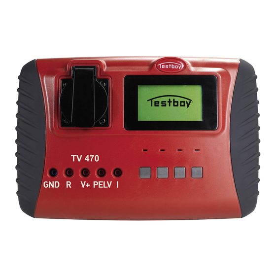
    Beschreibung Beschreibung Bedienelemente auf der Front A Prüfsteckdose B LCD-Anzeige C LED 1 Grün D LED 2 Gelb E LED 3 Rot F LED 4 Rot G Bedientasten H Anschlussbuchsen ® Testboy TV 470...
  • Seite 9 Die Bewertung der Messdaten durch die LED1 und LED3 entspre- chen nur den Grenzwerten von "normalen" Schutzklasse I Geräten. Die Bewertung ist nur als Hilfsmittel gedacht. Die jeweils gültigen Grenzwerte entnehmen Sie bitte dem Anhang dieser Anleitung bzw. der jeweils gültigen Norm. ® Testboy TV 470...
  • Seite 10: Anzeige

    Beschreibung Anzeige Die Anzeige des TV 470 ist in drei Bereiche eingeteilt. Im oberen Bereich werden Informationen zu den Einstellungen bzw. zur aktuellen Messung an- gezeigt. In der Mitte wird der Messwert angezeigt und in der unteren Zeile die derzeitige Funktion der darunterliegenden Taste.
  • Seite 11: Inbetriebnahme

    Inbetriebnahme Inbetriebnahme Der TV 470 schaltet sich automatisch ein, wenn der Netzstecker in die Steckdose gesteckt wird. Soll der Tester ausgeschaltet werden, müssen Sie den Netzstecker aus der Steckdose ziehen. Beim Einschalten läuft automatisch ein Selbsttest. Wird dieser ohne Fehler durchgeführt, erscheint der Startbildschirm im Display.
  • Seite 12: Einstellen Der Prüfnorm

    Auswahlmenü EN 62353 (VDE751-1) Schutzklasse Hier kann Schutzklasse I oder II eingestellt werden. Messungsart Hier wird eingestellt, ob Ableitströme per "Direktmessung" oder per "Ersatz- messung" gemessen werden. Anwendungstyp Hier wird der benötigte Anwendungsteil B, BF oder CF eingestellt. ® Testboy TV 470...
  • Seite 13: Einstellungen Im Punkt "Menü

    Messung durchgeführt wer- den soll. Die Datenspeicherung erfolgt nur im automatischen Modus. Datensätze Durch Auswahl von "Datensätze" können Sie durch vorhandene Datensätze blättern und sich gespeicherte Messwerte noch einmal anschauen. ® Testboy TV 470...
  • Seite 14 Um den Abgleich durchzuführen, schließen Sie eine Messleitung an die Buchse R an und messen zum Schutzleiterkontakt der Prüflingssteckdose. Drücken Sie nun die Taste "Speichern", um den Wert im Gerät zu hinterle- gen. Bei Wechsel der Messleitungen sollte die Messleitungskompensation erneut durchgeführt werden. ® Testboy TV 470...
  • Seite 15: Anschließen Und Verwenden Des Barcode-Scanners

    Inbetriebnahme Anschließen und Verwenden des Barcode-Scanners Schließen Sie den Barcode-Scanner an der Rückseite des TV 470 an. Der Scanner signalisiert die Funktionsbereitschaft durch ein akustisches Signal. Um einen Barcode zu erfassen, richten Sie den Scanner auf den Barcode und drücken Sie die Scannertaste. Das erfolgreiche Einlesen der Codes wird durch einen Signalton quittiert.
  • Seite 16: Schutzleiterwiderstandsmessung (R-Pe)

    Befindet sich der Messwert außerhalb der Messbereichsgrenzen des TV 470, so wird dieser Überlauf durch eine "1" im Display angezeigt. Zur Bewertung der Messdaten können die LED1 und LED3 zu Hilfe genom- men werden. Die voreingestellten Grenzwerte entsprechen denen von "nor- malen"...
  • Seite 17 Inbetriebnahme Bild 1 Bild 2 ® Testboy TV 470...
  • Seite 18: Isolationswiderstandsmessung (R-Iso)

    Aufleuchten der roten LED 4 angezeigt. Es stehen verschiedene Messmöglichkeiten zur Verfügung: Messung über die Prüfsteckdose (nur Geräte der Schutzklasse I) (Bild 3) Messung über die Messleitungen (Bild 4) Messung über die Prüfsteckdose und die Messleitungen (Bild 5 und 6) ® Testboy TV 470...
  • Seite 19 Neutralleiter) und dem Schutzleiter gemessen sowie allen berührbaren, leitfähigen Teilen, die nicht mit dem Schutzleiter verbunden sind. Bei Geräten der Schutzklasse II wird zwischen allen aktiven Teilen (Phase und Neutralleiter) sowie allen berührbaren, leitfähigen Teilen gemessen. Bild 4 ® Testboy TV 470...
  • Seite 20 Inbetriebnahme Bild 5 Bild 6 ® Testboy TV 470...
  • Seite 21: Ableitstrommessung (I-Abl)

    Führen Sie diese Messung niemals durch, bevor nicht die Schutzleiterwiderstands- und Isolationswiderstandsmessung erfolgreich durchgeführt worden sind! Der Prüfling wird während der Messung mit Netzspannung ver- sorgt und ist in Betrieb. Seien Sie deshalb vorsichtig mit Gerä- ten die Wärme abgeben oder bewegliche Teile besitzen! ® Testboy TV 470...
  • Seite 22: Ersatzableitstrommessung (I-Ea)

    Leitern (Phase und Neutralleiter) der Prüfsteckdose gelegt. Die Messleitung wird nur in folgenden Fällen benötigt: Bei Schutzklasse I-Geräten: Zur Überprüfung von berührbaren, leitfähi- gen Teilen die nicht mit dem Schutzleiter verbunden sind. Bei Schutzklasse II-Geräten: Zur Überprüfung von allen berührbaren, leitfähigen Teilen. ® Testboy TV 470...
  • Seite 23: Gleichspannungsmessung Bis 200 V Dc / Wechselspannungs- Messung Bis 200 V Ac

    "Mess" und wählen die gewünschte Messung (Gleichspannung bzw. Wech- selspannung) aus. Bestätigen Sie die Auswahl mit der Taste "Wählen". Der gemessene Wert wird nun angezeigt. Überschreitet der Messwert 25 V, wird dieses durch Aufleuchten der LED 3 (rot) angezeigt (Überschreitung der Ge- rätekleinspannung). ® Testboy TV 470...
  • Seite 24: Leistungsmessung Pwr

    Führen Sie diese Messung niemals durch, bevor nicht die Schutzleiterwiderstands- und Isolationswiderstandsmessung erfolgreich durchgeführt worden sind! Der Prüfling wird während der Messung mit Netzspannung ver- sorgt, seien Sie deshalb vorsichtig mit Geräten die Wärme ab- geben oder bewegliche Teile besitzen! ® Testboy TV 470...
  • Seite 25: Laststrommessung I-L

    Führen Sie diese Messung niemals durch, bevor nicht die Schutzleiterwiderstands- und Isolationswiderstandsmessung erfolgreich durchgeführt worden sind! Der Prüfling wird während der Messung mit Netzspannung ver- sorgt, seien Sie deshalb vorsichtig mit Geräten die Wärme ab- geben oder bewegliche Teile besitzen! ® Testboy TV 470...
  • Seite 26: Informationen Zur Din Vde 0701-0702:2008

    Grenzwerte < 0,3 Ω bis 5m Leitungslänge + 0,1 Ω je weitere 7,5 m Leitungslänge – max. 1 Ω Wichtige Hinweise Während der Messung die Anschlussleitungen bewegen. Messleitungswiderstand geht in Messung ein, Messleitungen gut leitend anschließen. ® Testboy TV 470...
  • Seite 27: Isolationswiderstand

    ISO/EA eine Schutzleiter- oder Berührungs- strommessung mit der direkten Methode oder indirekt als I erfolgen; bei der direkten Methode muss der Prüfling isoliert aufgestellt werden. Prüflinge SK2 ohne berührbare, leitfähige Teile können nur einer Sicht- prüfung unterzogen werden. ® Testboy TV 470...
  • Seite 28: Ersatzableitstrom

    Isolationsmessung nachgeholt werden. Abweichende Grenzwerte in DIN VDE0701Teil 1... 240 beachten! Halbierung des Messwertes bei allpolig abschaltbarer symmetrischer ka- pazitiver Beschaltung. Für mehrphasige Geräte ist die Messung des Ersatzableitstromes nicht geeignet. Geräte mit höheren Ableitströmen müssen gekennzeichnet sein. ® Testboy TV 470...
  • Seite 29: Berührungsstrom

    Teilen bei Geräten der Schutzklasse I, die nicht mit dem Schutz- leiter verbunden sind. Grenzwert DIN VDE 0701-0702:2008-6 < 0,5 mA Schutzkleinspannung Werte über den folgenden Angaben werden unter normalen Bedingungen als gefährlich aktiv angesehen. Grenzwert EN 61010-1:2011-07 33 V AC / 70V DC ® Testboy TV 470...
  • Seite 30: Informationen Zur Din En 62353 (Vde 0751-1:2008-8)

    Messspannung 4...24 V, Messstrom >200 mA Grenzwerte < 0,3 Ω inklusive Netzleitung Bei abnehmbaren Leitungen ggf. 0,2 oder 0,1 Ω Wichtige Hinweise Anschlussleitungen während der Messung bewegen Messleitungswiderstand geht in Messung ein, Messleitung gut leitend anschließen. ® Testboy TV 470...
  • Seite 31: Isolationswiderstand

    Schalter, Temperaturregler usw. geschlossen sind. Messspannung 500 VDC. Grenzwerte Schutzklasse DIN EN 62353 (VDE 0751-1) > 2 MΩ SK 1 > 7 MΩ > 70MΩ Anwendungsteil Typ CF Wichtige Hinweise Bei Schutzklasse 2-Prüflingen berührbare, leitfähige Teile mit Messlei- tung abtasten. ® Testboy TV 470...
  • Seite 32: Ersatz-Geräteableitstrom

    Werkzeuges bewegt werden kann. Beispiele: die Hauptteile einer Röntgeneinrichtung, wie der Röntgenstrahlenerzeu- ger, der Untersuchungs- oder Behandlungstisch. Geräte mit mineralisolierten Heizelementen. Geräte, die wegen Einhaltung von Funkschutzbestimmungen einen hö- heren Erdableitstrom als die bei "Erdableitstrom allgemein" zulässigen Werte aufweisen. ® Testboy TV 470...
  • Seite 33: Ersatz-Patientenableitstrom

    Typ des Anwendungsteils bestimmt den Grenzwert. Wenn bei der Ersatz-Geräteableitstrommessung nicht alle sicherheitsrele- vanten Teile erreicht werden, muss stattdessen eine Ableitstrommessung mit der direkten Methode oder indirekt als I erfolgen; bei der direkten Me- thode muss der Prüfling isoliert aufgestellt werden. ® Testboy TV 470...
  • Seite 34: Geräte-Ableitstrom

    Geräteableitstrom für Geräte der Schutzklasse 2 und nicht mit dem Schutzleiter verbundene leitfä- hige Teile von Geräten der Schutzklasse 1 Patientenableitstrom Zulässige Werte von langzeitig fließenden Er- Werte in mA satzableitströmen Anwendungsteil Patientenableitstrom Gleichstrom 0,01 – – Wechselstrom 0,10 – – ® Testboy TV 470...
  • Seite 35: Patientenableitstrom Netzspannung Am Anwendungsteil

    Informationen zur DIN EN 62353 (VDE 0751-1:2008-8) Patientenableitstrom Netzspannung am Anwendungsteil Zulässige Werte von langzeitig fließenden Er- Werte in mA satzableitströmen Anwendungsteil Patientenableitstrom Netzspannung am An- – 0,05 wendungsteil ® Testboy TV 470...
  • Seite 36: Anhang

    <3,5 mA Bei Geräten mit 2poliger Ab- 0,25 mA schaltung und Symmetri- scher kapazitiver Schaltung darf der Messwert beim Er- satzableitstrom halbiert wer- den. Schutzleiter- / Differenzstrom <3,5 mA >3,5 kW 1 mA/kW Berührungsstrom <0,5 mA ® Testboy TV 470...
  • Seite 37: Din En 62353 (Vde 0751-1:2008-8)

    10,0 mA 10,0 mA 10,0 mA nach Anmerkung 1 nach Anmerkung 2 Fahrbare Röntgengeräte mit zusätzli- 5,0 mA 5,0 mA 5,0 mA chem Schutzleiter Fahrbare Röntgengeräte ohne zusätzli- 2,0 mA 2,0 mA 2,0 mA chem Schutzleiter ® Testboy TV 470...
  • Seite 38 Untersuchungs- oder Behandlungstisch; Geräte mit mineralisolierten Heizelementen; Geräte, die wegen Einhaltung von Funkschutzbestimmun- gen einen höheren Erdableitstrom als die bei "Erdableitstrom allgemein" zu- lässigen Werte aufweisen. Anmerkung 3:Fahrbare Röntgengeräte und fahrbare Geräte mit minerali- scher Isolierung. ® Testboy TV 470...
  • Seite 39 Stand der Drucklegung und wurden nach bestem Wissen ermittelt. Für fehlerhafte Angaben, Irrtümer und Druckfehler wird keine juristische Verantwortung oder Haftung übernommen. Maßgebend für die Durchführung von Prüfungen sowie die Bestim- mung von Grenzwerten ist die jeweils gültige Norm im Original! ® Testboy TV 470...
  • Seite 40: Technische Daten

    Schutzleiterwiderstand Isolationswiderstand 0,15 – 200 M; ±5% Berührungsstrom 0,1 – 20 mA; ±5% Ersatzableitstrom 0,1 – 20 mA ; ±5% Laststrom 0,0 – 16 A; ±5% Leistung 0 – 3700 VA; ±5% PELV-Test ab 25 Veff ® Testboy TV 470...
  • Seite 41: Inhaltsverzeichnis

    DC voltage measurement up to 200V DC / AC current measurement up to 200 V AC Power measurement PWR Load current measurement I-L Information to DIN VDE 0701-0702:2008-06 PE conductor-resistance Insulation resistance Equivalent leakage current Contact current ® Testboy TV 470...
  • Seite 42 Equivalent device leakage current Equivalent patient leakage current Device leakage current Patient leakage current Patient leakage current at the mains voltage application part Appendix Limit according to DIN VDE 0701-0702:2008-06 DIN EN 62353 (VDE 0751-1:2008-8) Technical data ® Testboy TV 470...
  • Seite 43: Safety Precautions

    Safety precautions Safety precautions WARNING The TV 470 left the factory in proper and safe working order. In order to maintain this condition, the user must observe the safety notes contained in this manual. WARNING This operation manual contains information and notes required to operate and use this instrument safely.
  • Seite 44 5 year warranty Testboy instruments are subject to strict quality control standards. The in- strument is covered by a warranty for a period of five years against malfunc- tions during the course of your daily work (valid only with invoice). The in- strument does not require special maintenance when used as specified in this operation manual.
  • Seite 45 Safety precautions Certificate of quality All aspects of the activities carried out by Testboy GmbH relating to quality during the manufacturing process are monitored permanently within the framework of a Quality Management System. Furthermore, Testboy GmbH confirms that the testing equipment and instruments used during the calibra- tion process are subject to a permanent inspection process.
  • Seite 46: Description

    Description Description Front side controls A Test socket B LCD Indicators C LED 1 Green D LED 2 Yellow E LED 3 Red F LED 4 Red G Buttons H Connection socket ® Testboy TV 470...
  • Seite 47 "normal" protection class-I de- vices. The assessment is only considered to be as an aid. Refer to the appendix of this manual or the relevant standard for the appli- cable limits. ® Testboy TV 470...
  • Seite 48: Display

    Description Display The TV 470 display is divided into three areas. In the upper part, information concerning the current settings or measurements is shown. The measure- ment value is shown in the middle and in the lower line the function of the underlying key.
  • Seite 49: Preparing For First-Time Use

    Preparing for first-time use Preparing for first-time use The TV 470 switches on automatically when the mains plug is connected in- to the socket outlet. If the Tester is turned off the mains plug should be removed from the socket outlet.
  • Seite 50: Setting Up The Test Standard

    Protection class-I or II can be set. Type of measurement Selection of how leakage currents are measured, either by "direct measure- ment" or by "equivalent measurement". Application type Here the necessary application type B, BF or CF can be set. ® Testboy TV 470...
  • Seite 51: Settings In "Menu" Option

    Under the "Auto-measurement" option, either the test procedure should oc- cur automatically or the measurement should occur individually. The data storage only occurs in automatic mode. Records By selecting "records", you can browse through existing records and view previously stored readings. ® Testboy TV 470...
  • Seite 52 DUT (device under test) socket. Press the "Save" key to store the value in the device. When the test leads are changed, the test lead compensation should be re- peated. ® Testboy TV 470...
  • Seite 53: Connecting And Using The Bar Code Scanner

    Preparing for first-time use Connecting and using the bar code scanner. Connect the bar code scanner to the rear of the TV 470. An acoustic signal indicates that the scanner is ready. In order to read a bar code, aim the scanner at the bar code and press the scan key.
  • Seite 54: Pe Conductor Resistance Measurement (R-Pe)

    Preparing for first-time use "End". If the measured value is outside the range of the TV 470, the number "1" will be displayed on the screen. To evaluate the measurement result LED1 and LED2 can be used to help. The pre-set limits correspond to the "normal" protection class-I devices.
  • Seite 55 Preparing for first-time use Illustration 1 Illustration 2 ® Testboy TV 470...
  • Seite 56: Insulation Resistance Measurement (R-Iso)

    Several measurement options are available: Measurement using the test sockets (only for protection class-I devices) (Illustration 3) Measurement using the test leads (Illustration 4) Measurement using the test sockets and the test leads (Illustrations 5 and 6) ® Testboy TV 470...
  • Seite 57 PE conductor. With devices in protection class II, measurements will be made between all active parts (phase and neutral) as well as all exposed conductive compo- nents. Illustration 4 ® Testboy TV 470...
  • Seite 58 Preparing for first-time use Illustration 5 Illustration 6 ® Testboy TV 470...
  • Seite 59: Leakage Current Measurement (I-Abl)

    The DUT should be connected to the mains voltage and in op- eration during testing. Therefore, be careful with devices that emit heat or contain moving parts! ® Testboy TV 470...
  • Seite 60: Equivalent Leakage Current Measurement (I-Ea)

    The test leads are only needed in the following cases: With protection class-I devices: To test exposed conductive compo- nents that are not connected to the PE conductor. With protection class-II devices: To test all exposed conductive com- ponents. ® Testboy TV 470...
  • Seite 61: Dc Voltage Measurement Up To 200V Dc / Ac Current Measurement Up To 200 V Ac

    Then press "Measure" in the main menu and choose the desired measure- ment (DC or AC). Confirm by pressing the "Select" key. The measured value is displayed. If the measured value exceeds 25 V, LED3 illuminates (red) (exceeding the device low voltage range). ® Testboy TV 470...
  • Seite 62: Power Measurement Pwr

    Never carry out these measurements until the PE conductor resistance and the insulation resistance measurements have been successfully carried out! The DUT is connected to the mains voltage during measure- ments. Therefore, be careful with devices that emit heat or have moving parts! ® Testboy TV 470...
  • Seite 63: Load Current Measurement I-L

    Never carry out these measurements until the PE conductor resistance and the insulation resistance measurements have been successfully carried out! The DUT is connected to the mains voltage during measure- ments. Therefore, be careful with devices that emit heat or have moving parts! ® Testboy TV 470...
  • Seite 64: Information To Din Vde 0701-0702:2008

    < 0.3 Ω to 5m cable length + 0.1 Ω for each additional 7.5 m of cable length – max. 1 Ω Important notes Move the connection cables during measurement. As the test leads resistance is part of the measurement, the test leads should have a good electrical connection. ® Testboy TV 470...
  • Seite 65: Insulation Resistance

    PE conductor current measurement or a touch current measurement should be made instead of the ISO/EV test. Either the direct method or the indirect method I can be used. With the indirect method, the DUT has to be in an isolated position. ® Testboy TV 470...
  • Seite 66: Equivalent Leakage Current

    Note the different limit values in DIN VDE0701 Part 1 - 240! With an all-pole disconnecting capacitive circuitry switch, halve the measured value. Measuring the equivalent leakage current is not suitable for multi-phase devices. Devices with high leakage current should be marked as such. ® Testboy TV 470...
  • Seite 67: Contact Current

    PE conductor. Limit DIN VDE 0701-0702:2008-6 < 0.5 mA Low protection voltage Values above the following specifications should be viewed as actively dan- gerous under normal circumstances. Limit EN 61010-1:2011-07 33 V AC / 70V DC ® Testboy TV 470...
  • Seite 68: Information About Din En 62353 (Vde 0751-1:2008-8)

    With removable leads where applicable 0.2 or 0.1 Ω Important notes Move the connection cables during measurements As the test lead resistance is part of the measurement, the test lead should have a good electrical connection. ® Testboy TV 470...
  • Seite 69: Insulation Resistance

    Protection class DIN EN 62353 (VDE 0751-1) > 2 MΩ class-I > 7 MΩ class-II > 70MΩ Application part Type CF Important notes With protection class-II DUTs, exposed conductive components should be tested with the test leads. ® Testboy TV 470...
  • Seite 70: Equivalent Device Leakage Current

    The main part of an X-ray apparatus like the X-ray generator, the exami- nation table or the treatment table. Devices with mineral insulated heating elements. Devices that have a higher earth leakage current than is normally al- lowed, due to having to conform to the radio emission regulations. ® Testboy TV 470...
  • Seite 71: Equivalent Patient Leakage Current

    If all safety-relevant parts are not reached with the equivalent device leakage current, then a leakage current measurement should be made instead. Use either the direct method or the indirect method. With the indirect method, the DUT has to be in an isolated position. ® Testboy TV 470...
  • Seite 72: Device Leakage Current

    PE conductor conductive com- ponents. Patient leakage current Allowable values from long-term flow equiva- Value in mA lent leakage current Application part Patient leakage current Direct current 0.01 – – Alternating current 0.10 – – ® Testboy TV 470...
  • Seite 73: Patient Leakage Current At The Mains Voltage Application Part

    Information about DIN EN 62353 (VDE 0751-1:2008-8) Patient leakage current at the mains voltage application part Allowable values from long-term flow equiva- Value in mA lent leakage current Application part Patient leakage current Mains voltage on the – 0.05 application. ® Testboy TV 470...
  • Seite 74: Appendix

    PC II 0.25 mA current can be halved with devices that have a 2-pole switch and sym- metrical capacitive switching. PE conductor current / <3.5 mA >3.5 kW 1 mA/kW Differential current Contact current <0.5 mA ® Testboy TV 470...
  • Seite 75: Din En 62353 (Vde 0751-1:2008-8)

    10.0 mA cording to note 1 According to note 2 Mobile X-ray machines with additional 5.0 mA 5.0 mA 5.0 mA PE conductor Mobile X-ray machines without addi- 2.0 mA 2.0 mA 2.0 mA tional PE conductor ® Testboy TV 470...
  • Seite 76 Note 3: Mobile X-ray machines and mobile devices with mineral insulation. ® Testboy TV 470...
  • Seite 77 No legal responsibility or liability will be taken for any incorrect information, errors or printing mistakes. The relevant original valid directive is decisive for the implementa- tion of tests or determining limit values! ® Testboy TV 470...
  • Seite 78: Technical Data

    0.15 – 200 M; ±5% Contact current 0.1 – 20 mA; ±5% Equivalent leakage cur- 0.1 – 20 mA ; ±5% rent Load current 0.0 – 16 A; ±5% Power output 0 – 3700 VA; ±5% PELV-Test From 25 Veff ® Testboy TV 470...
  • Seite 79 Capaciteitsmeting PWR Fehler! Textmarke nicht definiert. Laststroommeting I-L Informatie over DIN VDE 0701-0702:2008-06Fehler! Textmarke nicht de Fehler! Textmarke nicht definiert. Aardgeleiderweerstand Fehler! Textmarke nicht definiert. Isolatieweerstand Fehler! Textmarke nicht definiert. Vervangende lekstroom Fehler! Textmarke nicht definiert. Aanraakstroom ® Testboy TV 470...
  • Seite 80 Patiëntlekstroom Patiëntlekstroom Netspanning op het toepassingsdeelFehler! Textmarke nicht def Fehler! Textmarke nicht definiert. Bijlage Grenswaarden DIN VDE 0701-0702:2008-06Fehler! Textmarke nicht definiert. Fehler! Textmarke nicht definiert. DIN EN 62353 (VDE 0751-1:2008-8) Fehler! Textmarke nicht definiert. Technische gegevens ® Testboy TV 470...
  • Seite 81: Voorzorgsmaatregelen

    Voorzorgsmaatregelen Voorzorgsmaatregelen WAARSCHUWING De TV 470 heeft de fabriek in veiligheidstechnisch onberispelijke staat verlaten. Om deze staat te behouden moet de gebruiker de veiligheidsinstructies in deze gebruiksaanwijzing opvolgen. WAARSCHUWING De gebruiksaanwijzing bevat informatie en aanwijzingen die voor een veilige bediening en veilig gebruik van het apparaat noodzakelijk zijn.
  • Seite 82 Voorzorgsmaatregelen Inleiding De TV 470 is een tester volgens DIN VDE 0701-0702 evenals DIN EN 62353 (VDE 0751-1). Het meetapparaat is volgens de nieuwste veiligheidsvoorschriften gebouwd en waarborgt veilig en betrouwbaar werken. Reiniging Als het apparaat door dagelijks gebruik vuil geworden is, kan het met een vochtige doek worden gereinigd.
  • Seite 83 Voorzorgsmaatregelen Kwaliteitscertificaat Alle binnen de firma Testboy GmbH uitgevoerde werkzaamheden en processen die relevant zijn voor de kwaliteit worden continu door een kwaliteitsmanagementsysteem bewaakt. De firma Testboy GmbH bevestigt daarnaast dat de gedurende de kalibratie gebruikte test-inrichtingen en instrumenten onderworpen zijn aan een voortdurende test.
  • Seite 84 Beschrijving Beschrijving Bedieningselementen op het front A Testcontactdoos B Lcd-display C Led 1 Groen D Led 2 Geel E Led 3 Rood F Led 4 Rood G Bedieningsknoppen H Connectoren ® Testboy TV 470...
  • Seite 85 De beoordeling van de meetgegevens door led 1 en led 3 komt slechts overeen met de grenswaarden van ‘normale’ Veiligheidsklasse I-apparaten. De beoordeling is slechts als hulpmiddel bedoeld. De geldende grenswaarden vindt u in de bijlage van deze gebruiksaanwijzing c.q. in de geldende norm. ® Testboy TV 470...
  • Seite 86 Beschrijving Aflezing De aflezing van de TV 470 is in drie zones ingedeeld. In het bovenste deel wordt informatie over de instellingen of over de huidige meting weergegeven. In het midden wordt de meetwaarde weergegeven en op de onderste regel de momentele functie van de eronder gelegen knop.
  • Seite 87 Ingebruikneming Ingebruikneming De TV 470 schakelt automatisch in als de netstekker in het stopcontact wordt gestoken. Als de tester moet worden uitgeschakeld, moet u de stekker uit het stopcontact trekken. Bij inschakeling wordt automatisch een zelftest uitgevoerd. Als hij zonder fouten wordt uitgevoerd, verschijnt het startmenu op het display.
  • Seite 88 Hier kan Veiligheidsklasse I of II worden ingesteld. Metingtype Hier wordt ingesteld of lekstromen door middel van ‘Directe meting’ of door middel van ‘Vervangende meting’ worden gemeten. Toepassingstype Hier wordt het benodigde toepassingsdeel B, BF of CF ingesteld. ® Testboy TV 470...
  • Seite 89 De gegevensopslag vindt alleen plaats in de automatische modus. Gegevensrecords Door selectie van ‘Gegevensrecords’ kunt u door voorhanden gegevensrecords bladeren en eerder opgeslagen meetwaarden nogmaals bekijken. ® Testboy TV 470...
  • Seite 90 Als in de toekomst wijzigingen in de norm of verdere ontwikkelingen van de embedded software ontstaan, is dit menu-item voor een firmware-update vereist. Gegevens en updates worden via onze website www.testboy.de ter beschikking gesteld. Visuele controle Als de visuele controlefunctie geactiveerd is, verschijnt vóór de apparaatcontrole een vraag die met een druk op de knop moet worden bevestigd.
  • Seite 91 Ingebruikneming Aansluiten en gebruiken van de barcodescanner Verbind de barcodescanner aan de achterzijde van de TV 470 aan. De scanner signaleert de gereedheid door middel van een akoestisch signaal. Om een barcode te scannen richt u de scanner op de barcode en drukt u op de scannerknop.
  • Seite 92 Bij apparaten uit veiligheidsklasse I en II kan de meting na de lekstroommeting door drukken op de knop ‘End’ worden beëindigd. Als de meetwaarde buiten de meetbereikgrenzen van de TV 470 ligt, wordt deze overloop door een ‘1’ weergegeven op het display.
  • Seite 93 Ingebruikneming Afb. 1 Afb. 2 ® Testboy TV 470...
  • Seite 94 4 weergegeven. Er staan verschillende meetmogelijkheden ter beschikking: Meting via de testcontactdoos (alleen Veiligheidsklasse I-apparaten) (afb. 3) Meting via de meetsnoeren (afb. 4) Meting via de testcontactdoos en van de meetsnoeren (afb. 5 en 6) ® Testboy TV 470...
  • Seite 95 Bij apparaten uit Veiligheidsklasse II wordt tussen alle actieve delen (fase en neutrale geleider) evenals alle aan te raken, geleidende delen gemeten. Afb. 4 ® Testboy TV 470...
  • Seite 96 Ingebruikneming Afb. 5 Afb. 6 ® Testboy TV 470...
  • Seite 97 Voer deze meting nooit uit zonder dat vooraf de aardgeleiderweerstands- en isolatieweerstandsmeting met succes uitgevoerd zijn! Het testobject wordt gedurende de meting met netspanning gevoed en is in werking. Wees daarom voorzichtig met apparaten die warmte afgeven of bewegende delen hebben! ® Testboy TV 470...
  • Seite 98 Het meetsnoer wordt alleen in de volgende gevallen gebruikt: Bij Veiligheidsklasse I-apparaten: Voor het testen van aan te raken, geleidende delen die niet met de aardgeleider verbonden zijn. Bij Veiligheidsklasse II-apparaten: Voor het testen van alle aan te raken, geleidende delen. ® Testboy TV 470...
  • Seite 99 Bevestig uw keuze met de knop ‘Selecteren’. De gemeten waarde wordt nu weergegeven. Als de meetwaarde groter is dan 25 V, wordt dit door oplichten van de led 3 (rood) weergegeven (overschrijding van de apparaatlaagspanning). ® Testboy TV 470...
  • Seite 100 Voer deze meting nooit uit zonder dat vooraf de aardgeleiderweerstands- en isolatieweerstandsmeting met succes uitgevoerd zijn! Het testobject wordt gedurende de meting met netspanning gevoed, wees daarom voorzichtig met apparaten die warmte afgeven of bewegende delen hebben! ® Testboy TV 470...
  • Seite 101 Voer deze meting nooit uit zonder dat vooraf de aardgeleiderweerstands- en isolatieweerstandsmeting met succes uitgevoerd zijn! Het testobject wordt gedurende de meting met netspanning gevoed, wees daarom voorzichtig met apparaten die warmte afgeven of bewegende delen hebben! ® Testboy TV 470...
  • Seite 102 < 0,3 Ω tot 5 m leidinglengte + 0,1 Ω elke volgende 7,5 m leidinglengte – max. 1 Ω Belangrijke informatie Gedurende de meting de aansluitleidingen bewegen. Meetsnoerweerstand wordt in de meting verdisconteerd, meetsnoeren goed geleidend aansluiten. ® Testboy TV 470...
  • Seite 103 ISO/EA een aardgeleider- of aanraakstroommeting met de directe methode of indirect als I plaatsvinden; bij de directe methode moet het testobject geïsoleerd worden geplaatst. Testobjecten SK2 zonder aan te raken, geleidende delen kunnen alleen aan een visuele controle worden onderworpen. ® Testboy TV 470...
  • Seite 104 Op afwijkende grenswaarden in DIN VDE 0701 Deel 1... 240 letten! Halvering van de meetwaarde bij op alle polen uitschakelbare symmetrische capacitieve schakeling. Voor meerfaseapparaten is de meting van de vervangende lekstroom niet geschikt. Apparaten met hogere lekstromen moeten gemarkeerd zijn. ® Testboy TV 470...
  • Seite 105 Veiligheidsklasse I, die niet met de aardgeleider verbonden zijn. Grenswaarde DIN VDE 0701-0702:2008-6 < 0,5 mA Veiligheidslaagspanning Waarden boven de volgende vermeldingen worden onder normale omstandigheden als ‘gevaarlijk actief’ beschouwd. Grenswaarde EN 61010-1:2011-07 33 V AC/70 V DC ® Testboy TV 470...
  • Seite 106 Meetstroom >200 mA Grenswaarden < 0,3 Ω inclusief netsnoer Bij afneembare leidingen indien nodig 0,2 of 0,1 Ω Belangrijke informatie Gedurende de meting de aansluitleidingen bewegen Meetsnoerweerstand wordt in de meting verdisconteerd, meetsnoer goed geleidend aansluiten. ® Testboy TV 470...
  • Seite 107 Meetspanning 500 V DC. Grenswaarden Veiligheidsklasse DIN EN 62353 (VDE 0751-1) > 2 MΩ > 7 MΩ > 70 MΩ Toepassingsdeel type CF Belangrijke informatie Bij Veiligheidsklasse 2-testobjecten aan te raken, geleidende delen met meetsnoer aftasten. ® Testboy TV 470...
  • Seite 108 De voornaamste onderdelen van een röntgeninrichting, zoals de röntgenstraalbron, de onderzoeks- of behandelingstafel. Apparaten met in mineraal materiaal geïsoleerde verwarmingselementen. Apparaten de wegens de naleving van ontstoringsbepalingen een hogere aardlekstroom dan de bij ‘Aardlekstroom algemeen’ toelaatbare waarden hebben. ® Testboy TV 470...
  • Seite 109 Als bij de vervangende apparaatlekstroommeting niet alle veiligheidsrelevante delen worden bereikt, moet in plaats daarvan een lekstroommeting met de directe methode of indirect als I plaatsvinden; bij de directe methode moet het testobject geïsoleerd worden geplaatst. ® Testboy TV 470...
  • Seite 110 Veiligheidsklasse 2 en niet met de aardgeleider verbonden, geleidende delen van apparaten uit Veiligheidsklasse 1 Patiëntlekstroom Toelaatbare waarden voor langdurig vloeiende Waarden in mA vervangende lekstromen Toepassingsdeel Patiëntlekstroom Gelijkstroom 0,01 – – Wisselstroom 0,10 – – ® Testboy TV 470...
  • Seite 111 Informatie over DIN EN 62353 (VDE 0751-1:2008-8) Patiëntlekstroom Netspanning op het toepassingsdeel Toelaatbare waarden voor langdurig vloeiende Waarden in mA vervangende lekstromen Toepassingsdeel Patiëntlekstroom Netspanning op het – 0,05 toepassingsdeel ® Testboy TV 470...
  • Seite 112 >0,25 MΩ Vervangende <3,5 mA Bij apparaten met 2-polige lekstroom 0,25 mA uitschakeling en symmetrische capacitieve schakeling mag de meetwaarde bij de vervangende lekstroom worden gehalveerd. Aardgeleider-/verschilstroom <3,5 mA >3,5 kW 1 mA/kW Aanraakstroom <0,5 mA ® Testboy TV 470...
  • Seite 113 10,0 mA 10,0 mA 10,0 mA volgens opmerking 1 volgens opmerking 2 Mobiele röntgenapparaten met 5,0 mA 5,0 mA 5,0 mA aanvullende aardgeleider Mobiele röntgenapparaten zonder 2,0 mA 2,0 mA 2,0 mA aanvullende aardgeleider ® Testboy TV 470...
  • Seite 114 ‘Aardlekstroom algemeen’ toelaatbare waarden hebben. Opmerking 3: Mobiele röntgenapparaten en mobiele apparaten met minerale Isolatie. ® Testboy TV 470...
  • Seite 115 Voor foutieve gegevens, vergissingen en drukfouten wordt geen juridische verantwoordelijkheid of aansprakelijkheid aanvaard. Doorslaggevend voor de uitvoering van tests evenals de bepaling van grenswaarden is de geldende norm in de oorspronkelijke versie! ® Testboy TV 470...
  • Seite 116: Technische Gegevens

    0,15 – 200 M; ±5 % Aanraakstroom 0,1 – 20 mA; ±5 % Vervangende lekstroom 0,1 – 20 mA; ±5 % Laststroom 0,0 – 16 A; ±5 % Vermogen 0 – 3700 VA; ±5 % PELV-test vanaf 25 V eff. ® Testboy TV 470...
  • Seite 117: Índice

    200 V CA   Medição do desempenho PWR   Medição da corrente de carga-L Informação sobre DIN VDE 0701-0702:2008-06     Resistência do condutor PE   Resistência do isolamento   Corrente de fuga equivalente   Corrente de contacto ® Testboy TV 470...
  • Seite 118 Corrente de fuga do paciente Tensão de rede da corrente de fuga do paciente no componente   de aplicação Apêndice     Limite de acordo com DIN VDE 0701-0702:2008-06   DIN EN 62353 (VDE 0751-1:2008-8) Dados técnicos   ® Testboy TV 470...
  • Seite 119: Precauções De Segurança

    Precauções de segurança Precauções de segurança AVISO O TV 470 saiu da fábrica em condições para funcionar com segurança. A fim de manter esta condição, o utilizador deve respeitar as notas de segurança contidas neste manual. AVISO Este manual contém informação e notas necessárias ao bom funcionamento e utilização deste aparelho com segurança.
  • Seite 120 Precauções de segurança Introdução O TV 470 é um instrumento de teste que está em conformidade com as diretrizes DIN VDE 0701-0702 e DIN EN 62353 (VDE 0751-1). Este instrumento de medição foi fabricado de acordo com as últimas especificações de segurança e garante uma utilização segura e de confiança.
  • Seite 121 Precauções de segurança Certificado de qualidade Todos os aspetos das atividades realizadas pela Testboy GmbH que dizem respeito à qualidade do processo de fabrico são monitorizados permanentemente dentro dos padrões de um Serviço de Gestão de Qualidade. Além disso, a Testboy GmbH confirma que o equipamento de teste e os instrumentos usados durante o processo de calibração estão...
  • Seite 122: Descrição

    Descrição Descrição Controlos do painel dianteiro A Tomada de teste B Indicadores do LCD C LED 1 Verde D LED 2 Amarelo E LED 3 Vermelho F LED 4 Vermelho G Botões H Tomada de ligação ® Testboy TV 470...
  • Seite 123 A avaliação dos dados de medição através do LED1 e LED3 corresponde apenas aos limites dos aparelhos de proteção "normal" de classe I. A avaliação é apenas considerada como uma ajuda. Consulte o apêndice deste manual ou a norma relevante para os limites aplicáveis. ® Testboy TV 470...
  • Seite 124: Ecrã

    Descrição Ecrã O ecrã do TV 470 está dividido em três áreas. Na parte superior surge a informação relativa às configurações ou medições atuais. O valor da medição é apresentado a meio e na linha inferior surge a função da tecla subjacente.
  • Seite 125: Preparação Para A Primeira Utilização

    Preparação para a primeira utilização Preparação para a primeira utilização O TV 470 liga-se automaticamente quando a ficha de corrente é ligada à tomada de saída. Se desligar o instrumento de teste, deve remover a ficha de corrente da tomada de saída.
  • Seite 126: Configuração Do Padrão De Teste

    Tipo de medição Pode-se selecionar o modo de medição das correntes de fuga: ou por "medição direta" ou por "medição equivalente". Tipo de aplicação Aqui pode-se configurar o tipo de aplicação necessária: tipo B, BF ou CF. ® Testboy TV 470...
  • Seite 127: Configurações Na Opção "Menu

    Na opção medição automática, ou o procedimento de teste ocorre automaticamente, ou a medição se realiza individualmente. O armazenamento de dados só se realiza no modo automático. Registos Ao selecionar registos (records), pode navegar através de registos já existentes e visualizar leituras previamente armazenadas. ® Testboy TV 470...
  • Seite 128 à terra da tomada do aparelho a testar (DUT). Pressione a tecla "Gravar" (Save) para armazenar o valor no aparelho. Quando os cabos de teste forem mudados, deve-se repetir a compensação dos cabos de teste. ® Testboy TV 470...
  • Seite 129: Ligação E Utilização Do Leitor De Código De Barras

    Preparação para a primeira utilização Ligação e utilização do leitor de código de barras. Conexão do leitor de código de barras (scanner) à parte de trás do TV 470. Um sinal acústico indica que o leitor está pronto. Para ler um código de barras, aponte o leitor ao código de barras e pressione a tecla de digitalização.
  • Seite 130: Medição Da Resistência Do Condutor Pe (R-Pe)

    "End" (fim). Se o valor da medição estiver fora do alcance do TV 470, o número "1" surgirá no ecrã. Para ajudar na avaliação do resultado da medição, pode-se usar LED1 e LED2.
  • Seite 131 Preparação para a primeira utilização Figura 1 Figura 2 ® Testboy TV 470...
  • Seite 132: Medição Da Resistência Do Isolamento (R-Iso)

    Medição usando as tomadas de teste (só para dispositivos de proteção de classe I) (Figura 3) Medição usando os cabos de teste (Figura 4) Medição usando as tomadas de teste e os cabos de teste (Figuras 5 e 6) ® Testboy TV 470...
  • Seite 133 PE. Nos dispositivos de proteção de classe II, as medições serão feitas entre todas as linhas ativas (fase e neutro), assim como todos os componentes condutores expostos. Figura 4 ® Testboy TV 470...
  • Seite 134 Preparação para a primeira utilização Figura 5 Figura 6 ® Testboy TV 470...
  • Seite 135: Medição Da Corrente De Fuga (I-Abl)

    PE e da resistência do iso-lamento terem sido realizadas com êxito! Durante o teste, o aparelho a testar deve estar liga-do à fonte de alimentação e em funcionamento. Por isso, tenha cuidado com dispositivos que emitem calor ou que contêm peças móveis! ® Testboy TV 470...
  • Seite 136: Medição Da Corrente De Fuga Equivalente (I-Ea)

    Os cabos de teste são necessários apenas nos seguintes casos: Em dispositivos de proteção de classe-I: Para testar os componentes condutores expostos que não estão ligados ao condutor PE. Em dispositivos de proteção de classe-II: Para testar todos os componentes condutores expostos. ® Testboy TV 470...
  • Seite 137: Medição Da Tensão Cc Até 200V Cc / Medição Da Corrente Ca Até 200 V Ca

    AVISO Este aparelho não é adequado para testar ou medir tensões de rede. Apenas foi concebido para medir tensões CC ou CA até um máximo de 200 V. ® Testboy TV 470...
  • Seite 138: Medição Do Desempenho Pwr

    PE e da resistência do iso-lamento terem sido realizadas com êxito! Durante o teste, o aparelho a testar está ligado à fonte de alimentação. Por isso, tenha cuidado com dispositivos que emitem calor ou que contêm peças móveis! ® Testboy TV 470...
  • Seite 139: Medição Da Corrente De Carga-L

    PE e da resistência do iso-lamento terem sido realizadas com êxito! Durante o teste, o aparelho a testar está ligado à fonte de alimentação. Por isso, tenha cuidado com dispositivos que emitem calor ou que contêm peças móveis! ® Testboy TV 470...
  • Seite 140: Informação Sobre Din Vde 0701-0702:2008

    – max. 1 Ω Notas importantes Mude os cabos de ligação durante as medições. Os cabos de teste devem ter uma boa ligação elétrica, uma vez que a resistência dos cabos de teste faz parte da medição. ® Testboy TV 470...
  • Seite 141: Resistência Do Isolamento

    Se não forem alcançados todos os componentes de segurança relevantes durante as medições do isolamento, deve-se proceder à medição da corrente do condutor PE ou à medição da corrente de contacto, em vez de se fazer um teste de isolamento. Pode-se usar o ® Testboy TV 470...
  • Seite 142: Corrente De Fuga Equivalente

    Tenha em consideração os diferentes valores limite da DIN VDE0701 Parte 1 - 240! Reduza para metade o valor medido, com um interrutor de circuito capacitivo desconector de todos os polos. ® Testboy TV 470...
  • Seite 143: Corrente De Contacto

    PE. Limite DIN VDE 0701-0702:2008-6 < 0.5 mA Tensão de baixa proteção Os valores acima das especificações seguintes devem ser considerados como ativamente perigosos em circunstâncias normais. Limite EN 61010-1:2011-07 33 V AC / 70V DC ® Testboy TV 470...
  • Seite 144: Informação Sobre Din En 62353 (Vde 0751-1:2008-8)

    Com cabos amovíveis no caso de 0.2 ou 0.1 Ω Notas importantes Mude os cabos de ligação durante as medições. Uma vez que a resistência do cabo de teste faz parte da medição, o cabo de teste deve ter uma boa ligação elétrica. ® Testboy TV 470...
  • Seite 145: Resistência Do Isolamento

    > 2 MΩ classe-I > 7 MΩ classe-II > 70MΩ Componente de aplicação Tipo CF Notas importantes Nos aparelhos a testar com proteção de classe II, os componentes condutores expostos devem ser testados com os cabos de teste. ® Testboy TV 470...
  • Seite 146: Dispositivo De Corrente De Fuga Equivalente

    Dispositivos com elementos de aquecimento com isolamento mineral. Dispositivos que possuem uma corrente de fuga à terra mais elevada do que o normalmente permitido, devido a terem de estar em conformidade com as normas de emissão de radiações. ® Testboy TV 470...
  • Seite 147: Corrente De Fuga Do Paciente - Equivalente

    Use o métodoI direto ou indireto. No caso do método indireto, o aparelho a testar tem de estar numa posição isolada. ® Testboy TV 470...
  • Seite 148: Dispositivos - Corrente De Fuga

    Corrente de fuga do paciente Valor em mA Valores permitidos da corrente de fuga equivalente, de fluxo de longo-prazo Componente de aplicação Corrente de fuga do Corrente contínua 0.01 – – paciente Corrente alternada 0.10 – – ® Testboy TV 470...
  • Seite 149: Tensão De Rede Da Corrente De Fuga Do Paciente No Componente De Aplicação

    Tensão de rede da corrente de fuga do paciente no componente de aplicação Valores permitidos da corrente de fuga Valor em mA equivalente, de fluxo de longo-prazo Componente de aplicação Corrente de fuga do Tensão de rede na – 0.05 paciente aplicação ® Testboy TV 470...
  • Seite 150: Apêndice

    Corrente do condutor PE / <3.5 mA >3.5 kW 1 mA/kW Corrente diferencial Corrente de contacto <0.5 mA ® Testboy TV 470...
  • Seite 151: Din En 62353 (Vde 0751-1:2008-8)

    5.0 mA condutor PE adicional Máquinas de raios-X móveis sem um 2.0 mA 2.0 mA 2.0 mA condutor PE adicional Corrente de fuga do paciente 0.01 mA, 0.01 mA, 0.01 mA, 0.1 mA 0.1 mA 0.1 mA ® Testboy TV 470...
  • Seite 152 Dispositivos que possuem uma corrente de fuga à terra mais elevada do que o normalmente permitido, devido a terem de estar em conformidade com as normas de emissão de radiações. Nota 3: Máquinas móveis de raios-X com isolamento mineral. ® Testboy TV 470...
  • Seite 153 Não se assume qualquer tipo de responsabilidade legal por qualquer informação incorreta, erros ou falhas de impressão. A diretiva válida e relevante no original é decisiva para a implementação de testes assim como para a determinação de valores limite! ® Testboy TV 470...
  • Seite 154: Dados Técnicos

    0.1 – 20 mA; ±5% Corrente de fuga 0.1 – 20 mA ; ±5% equivalente Corrente de carga 0.0 – 16 A; ±5% Potência de saída 0 – 3700 VA; ±5% Teste PELV A partir de 25 Vrms ® Testboy TV 470...
  • Seite 160 Testboy GmbH Tel: 0049 (0)4441 / 89112-10 Elektrotechnische Spezialfabrik Fax: 0049 (0)4441 / 84536 Beim Alten Flugplatz 3 D-49377 Vechta www.testboy.de Germany info@testboy.de...

Inhaltsverzeichnis