Inhaltsverzeichnis
Werbung
Verfügbare Sprachen
Verfügbare Sprachen
Quicklinks
Camille Bauer AG
Aargauerstrasse 7
CH-5610 Wohlen/Switzerland
Telefon +41 56 618 21 11
Telefax +41 56 618 35 35
info@camillebauer.com
www.camillebauer.com
Betriebsanleitung
Messumformer für Stellung
KINAX SR 719
Operating Instructions
Transmitter for Position Feedback
KINAX SR 719
SR 719 Bde
151 217-03
06.10
1
Werbung
Kapitel
Inhaltsverzeichnis

Verwandte Anleitungen für Camille Bauer KINAX SR 719


Inhaltszusammenfassung für Camille Bauer KINAX SR 719
- Seite 1 Betriebsanleitung Messumformer für Stellung KINAX SR 719 Operating Instructions Transmitter for Position Feedback KINAX SR 719 SR 719 Bde 151 217-03 06.10 Camille Bauer AG Aargauerstrasse 7 CH-5610 Wohlen/Switzerland Telefon +41 56 618 21 11 Telefax +41 56 618 35 35 info@camillebauer.com...
-
Seite 3: Programmierbarer Messumformer Für Stellung
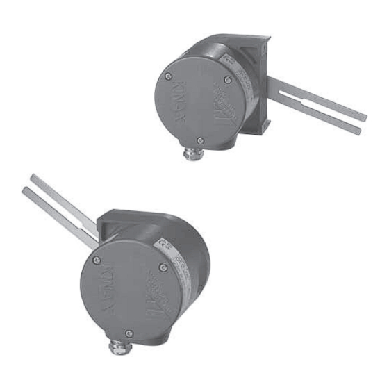
Programmierbarer Messumformer für Stellung Stellungsmelder für Ventilanbau nach NAMUR Verwendung Der Stellungs-Rückmelder KINAX SR 719 (Bilder 1 und 2) dient zum Erfassen von Hüben an Ventilen, Drosselklappen, Schiebern und anderen Stellgliedern und formt diese Messgrösse in einen eingeprägten, dem Messwert proportionalen Gleichstrom um. -
Seite 4: Programmierung
Listenblatt: PK 610 Ld.) Die Zusammenschaltung α μP «PC ↔ PK 610 ↔ KINAX SR 719» geht aus Bild 7 hervor. Der Programmiervorgang ist sowohl mit als auch ohne Hilfsenergie- anschluss durchführbar. Die Software 2W2 wird auf einer CD geliefert, sie läuft unter RS 232 Windows 95 oder höher. -
Seite 5: Programmier-Anschluss
KINAX SR 719 Programmierbarer Messumformer für Stellung Restwelligkeit des Mögliche Messbereich- Ausgangsstromes: < 0,3% p.p. Einstellung am eingebauten KINAX 2W2 > 50…350° Einstellzeit: < 5 ms Kennlinie linear Programmier-Anschluss Der Messbereich wird auf ca. 0…90º eingestellt. Schnittstelle: Serielle Schnittstelle Einfl usseffekte (Maximalwerte) - Seite 6 Temperatur – 40 bis + 75 °C Deckel Rel. Feuchte im Jahresmittel ≤ 95% Stopfbuchse Transport- und Bild 8. KINAX SR 719 mit Schraubklemmen und Stopfbuchse. Lagerungs-Temperatur: – 40 bis 80 °C Tabelle 2: Aufschlüsselung der Varianten Bestell-Code 719 – Auswahl-Kriterium, Varianten *SCODE unmöglich...
-
Seite 7: Elektrische Anschlüsse
Normales Zubehör für Camille Bauer-Produkte 1 Betriebsanleitung, dreisprachig: Deutsch, Französisch, Englisch Mass-Skizzen 15,5 PG 11 Bild 9. KINAX SR 719, Lage des Anschlusshebels bei Ruhestellung nach unten gerichtet, entspricht Ausgangsstrom 4 mA. Camille Bauer Datenblatt SR 719 Ld – 02.08... - Seite 8 KINAX SR 719 Programmierbarer Messumformer für Stellung 15,5 PG 11 Bild 10. KINAX SR 719, Lage des Anschlusshebels bei Ruhestellung nach oben gerichtet, entspricht Ausgangsstrom 4 mA. 2 Befestigungsbügel oder Schraube M8 Anbaulasche Bild 11. KINAX SR 719, Anbau nach NAMUR-Empfehlung.
- Seite 9 KINAX SR 719 Programmierbarer Messumformer für Stellung Bild 12. NAMUR-Anbausatz. Auf uns ist Verlass. Camille Bauer AG Aargauerstrasse 7 CH-5610 Wohlen / Schweiz Telefon: +41 56 618 21 11 Telefax: +41 56 618 35 35 e-Mail: info@camillebauer.com www.camillebauer.com Änderungen vorbehalten • Ausgabe 02.08 • Datenblatt SR 719 Ld...
-
Seite 10: Inhaltsverzeichnis
Sicherheitshinweise, die unbedingt beachtet werden müssen, sind in dieser Betriebsanleitung mit folgendenden Symbolen markiert: Messumformer für Drehwinkel KINAX 2W2 Camille Bauer AG Aargauerstrasse 7 CH-5610 Wohlen/Switzerland Telefon +41 56 618 21 11 Geräte dürfen nur fachgerecht entsorgt werden! Telefax +41 56 618 35 35 info@camillebauer.com... -
Seite 11: Technische Daten
5. Technische Daten 6. Montage und Inbetriebnahme Mechanische Voraussetzungen zur Montage Messeingang Sämtliche Messumformervarianten dieser Baureihe lassen sich entweder Drehwinkel-Messbereich: Programmierbar zwischen 0 bis 10 und 0 bis 50 unmittelbar oder mit 3 Spannklammern am Messobjekt montieren. Beide oder Montagearten und die zugehörigen Bohr-Ausschnitts-Pläne sind Inhalt der 0 bis 50 und 0 bis 350 °... -
Seite 12: Mass-Skizzen
Anlagen in explosionsgefährdeten Bereichen zu berücksichtigen! – 0,008 Ø 2 – 0,014 KINAX 2W2 Supply Range: 0…350º linear Camille Bauer AG Voltage Output: 2-Wire Aargauerstr. 7 Type: 760 - 1211 1D0 CH-5610 Wohlen 4…20 mA 12…33V 120° 16,5... -
Seite 13: Konformitätserklärung
8. Konformitätserklärung 4,5 tief EG - KONFORMITÄTSERKLÄRUNG EC DECLARATION OF CONFORMITY D o k u m e n t - N r . / 2 W 2 _ C E - k o n f . D O C D o c u m e n t . N o . : H e r s t e l l e r / C a m i l l e B a u e r A G M a n u f a c t u r e r :... -
Seite 24: Declaration Of Conformity
8. Declaration of conformity 4.5 low EG - KONFORMITÄTSERKLÄRUNG EC DECLARATION OF CONFORMITY D o k u m e n t - N r . / 2 W 2 _ C E - k o n f . D O C D o c u m e n t .