Herunterladen Inhalt Inhalt Diese Seite drucken
Inhaltsverzeichnis

Werbung

Verfügbare Sprachen

Verfügbare Sprachen

D
Montage- und
Bedienungsanleitung
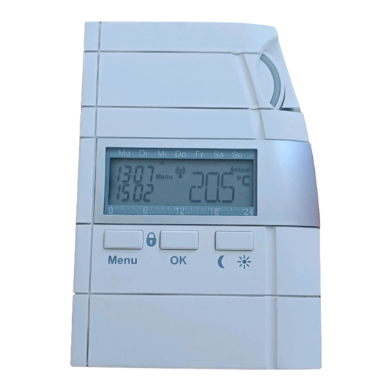
Funk-Wandthermostat
HM-CC-TC
Seite 4 - 30
Installation and
Operating Manual
GB
Radio-controlled
room thermostat
HM-CC-TC
Page 32 - 58

Werbung

Inhaltsverzeichnis
loading

Inhaltszusammenfassung für HomeMatic HM-CC-TC

  • Seite 1 Montage- und Bedienungsanleitung Funk-Wandthermostat HM-CC-TC Seite 4 - 30 Installation and Operating Manual Radio-controlled room thermostat HM-CC-TC Page 32 - 58...
  • Seite 2: Inhaltsverzeichnis

    Function........34 General system information on HomeMatic ...36 General information on radio operation .
  • Seite 3 Button lock ........46 Lowered mode with open windows ....46 Configuration and special functions .
  • Seite 4: Information Concerning These Instructions

    Do not open the device. It does not contain any parts to be main- tained by the user. Function The radio-controlled room thermostat (HM-CC-TC) is a single room controller. It measures the room temperature and compares the measured temperature with the set temperature defined by the time program or manually.
  • Seite 5 HomeMatic center. Controlling continues to be performed self- sufficiently by the room thermostat in the respective room. Teaching one or more shutter contacts or window rotary handle...
  • Seite 6: General System Information On Homematic

    General system information on HomeMatic This device is a part of the HomeMatic home control system and works with the bidirectional BidCoS® wireless protocol. All devices are delivered in a standard configuration. The func- tionality of the device can also be configured with a program- ming device and software.
  • Seite 7: Start Up

    Mark the bore holes using the wall holder for mounting the room thermostats on the wall. Position the wall holder with the semi- circle formed side to the top and the side with the small hemi- spherical formed indentation in the top part to the front. Mark a position in the middle of the elongated holes for the screws.
  • Seite 8: Behavior After Inserting The Battery

    6.1.2 Behavior after inserting the battery A short test of the LC display is performed after inserting the bat- tery and then the version number is displayed. Now enter the date and the time. This is done using the setting dial.
  • Seite 9: Changing Batteries

    The date and time are now set in the heating controller and the standard display appears again. If the heating controller is taught on a center, the controller will request the date and time from the center when the battery is changed next and if this is successful, the standard display appears again immediately.
  • Seite 10: Installation

    Installation 6.2.1 Scope of delivery 6.2.2 Mounting the wall holder Mark the bore holes using the wall holder for mounting the room thermostats on the wall. Position the wall holder with the semi- circle formed side to the top and the side with the small hemi- spherical formed indentation in the top part to the front.
  • Seite 11: Operation

    The heating controller has three modes in stand-alone opera- tion (operation without a HomeMatic center), automatic mode, manual mode and vacation/party mode. If the heating controller is linked to a HomeMatic center, central operation is also pos- sible. You can switch between the individual modes of operation with the menu button.
  • Seite 12: Operating Modes

    The respective device can be found easily through the "Special functions" menu "VST" or "WST". If only the battery symbol appears, the messages applies only to the room thermostats. Operating modes 7.2.1 Automatic mode The room temperature follows the defined weekday program in automatic mode (display "Auto").
  • Seite 13: Center-Controlled Operation

    If a door-window contact or a window rotary handle sensor is integrated into the system, the door- or window-position is taken into account during Vacation/Party mode as well, i.e. if a moni- tored door or window is open, the window-open temperature is selected for the control.
  • Seite 14: Factory Settings

    Factory settings When delivered, all of the required systems settings are defined with default values: taught) You can change all of the settings indicated and adapt them to your individual requirements. Resetting to the factory settings can be done at any time via Menu "Special functions": "RES". Setting the comfort and lowered temperatures Use the "Day/Night"...
  • Seite 15: Heating Pause

    Use the setting dial to select the desired comfort temperature and confirm your entry with the "OK" button. The display will now change for entering the lowered tempera- ture. Use the setting dial to select the desired lowered temperature and confirm your entry with the "OK" button. After setting the comfort and the lowered temperatures, the default display appears again.
  • Seite 16: Freeze Protection Mode

    Freeze protection mode Select this operating mode if the room is not to be heated at all. To close the valve, switch manual mode ("Manu") with the "Menu" button and turn the setting dial to the left until "OFF" appears on the display. Button lock In order to protect the device from accidental, incorrect adjust- ments, a lock function has been integrated for the buttons and...
  • Seite 17 Example: Window-open Sensor temperature HM-Sec-SC (1) Window 1 HM-Sec-SC (2) Window 2 HM-Sec-RHS Window 3 If window 3 is closed however (1 and 2 remain open), it switches and 3 are closed. If all windows are indicated as closed, the room control- ler is set back to the original temperature.
  • Seite 18: Configuration And Special Functions

    Valve position, battery status and reception station dis- plays Window position, battery status and reception station displays HomeMatic device configuration Decalcification procedure time definition Temperature unit definition (Celsius or Fahrenheit) Definition of whether actual or set value should be dis-...
  • Seite 19: Settings For Automatic Mode "Prg

    Settings for automatic mode "PRG" The time for automatically switching between the various tem- perature phases can be changed separately for each weekday, which enables the adapation to personal lifestyles. When setting the individual phases, the starting time for the respective temperature phase is always shown in the top line of the left-hand margin and indicates the previous temperature phase automatically with the end time.
  • Seite 20 Use the setting dial to define the end time for the first tempera- ture phase and confirm the entry with the "OK" button. The set temperature for the selected time range appears on the display. Use the setting dial to set the desired temperature. As an alterna- tive, you can select the comfort temperature or the lowered tem- perature as temperature with the "Moon/Sun"...
  • Seite 21: Setting The Date And Time "Dat

    Shut down the time program by setting 00:00 hrs. as the end time. 00:00 is automatically set as the end time, if 24 temperature phases have been created.Program completion is indicated on the display with "OK". Setting the date and time "DAT" Call up special function "DAT".
  • Seite 22: Teaching And Unteaching Of Devices "Kon

    Press the "OK" button to call up the information on the sensors. The window symbol and the window position ("OPE" or "CLO") are shown on the display. If the battery is low, the battery symbol will also be shown. If the radio connection between the sensor and the controller is interrupted, the antenna symbols will also flash.
  • Seite 23: Automatic Decalcification Procedure Settings "Dec

    sors are indicated by the window symbol in addition to their device number on the display. Confirm the unteach- ing with the "OK" button. After successfully unteaching, "OK" appears on the display for approx. 3 seconds. You can also activate teaching mode by pressing the "OK" but- ton with an extended button press (>...
  • Seite 24: Configuring The Display Of Set-/Actual Values "A/S

    Configuring the display set/actual values "A/S" You can display whether the actual or set temperature should be displayed under this menu point. Call up special function "A/S" and confirm with the "OK" button. Now, you can use the setting dial to choose between "Actual" (actual temperature) and "Set"...
  • Seite 25: Setting The Offset Values For The Individual Actuator "Off

    8.11 Setting the offset values for the individual actuator "OFF" If multiple actuators on various heaters are controlled by the same controller, the heating of the individual heaters may be uneven. This may be because of a severe non-uniform valve flow between the valves and/or poorly dimensioned heaters.
  • Seite 26: Setting The Position For Errors On The Actuator "Epo

    8.13 Setting the position for errors on the actuator "EPO" If the batteries of the valve drive are low or if the communication to the heating controller is erroneous, the valve drive moves to the defined error position and remains in this position until the error is rectified.
  • Seite 27: Error Messages

    Error messages If the radio communication with a valve drive or a learned sensor is disrupted, the antenna symbol flashes on the display. The information on the device types is also provided by means of letters "S" and "V". You can determine the affected device with more precision with special function "VST"...
  • Seite 28: Technical Specifications

    Technical specifications Radio frequency: 868.3 MHz Typ. outdoor range: 100 m Power supply: 2 x LR6 (Mignon) Protection type: IP20 Housing: Housing color: Pure white, silver faceplate Display: LCD 44 x 15 mm (backlit) Dimensions: 76 x 110 x 25 mm (W x H x D) Weight: 100 g (without batteries) Battery lifespan:...
  • Seite 30 eQ-3 AG Maiburger Straße 29 D-26789 Leer www.eQ-3.com...
  • Seite 31: Adapter Für Danfoss Heizkörperventile

    Montageanleitung Adapter für Danfoss Heizkörperventile _______________________________________ 1. Ausgabe Deutsch 03/2008 Dokumentation © 2008 eQ-3 Ltd., Hong Kong Alle Rechte vorbehalten. Ohne schriftliche Zustimmung des Herausgebers darf diese Anleitung auch nicht auszugsweise in irgendeiner Form reproduziert werden oder un- ter Verwendung elektronischer, mechanischer oder chemischer Verfahren vervielfältigt oder verarbeitet werden.
  • Seite 32 Gefahrenhinweis Achtung: Wenn der Thermostatkopf demontiert wird, öffnet sich das Ventil am Heizkörper. Unter Umständen können sich der Heizkörper und dessen Anschlüsse dann stark erwärmen. Ggf. sollte die Heizungsanlage während der Montage des Adapters außer Betrieb genommen, oder der Heizkörper an der Rücklaufverschraubung abgesperrt werden.
  • Seite 33 Welcher Adapterring zu welchem Ventil gehört, ist aus den nebenstehenden Bildern ersichtlich. Die Adapterringe RA und RAV sind nach dem Aufrasten mit der beiliegenden Mutter und Schraube zu befestigen. Bei Ventilen vom Typ RAV ist außerdem die Stößelverlängerung auf den Ventil- stößel zu stecken.
  • Seite 34 eQ-3 AG Maiburger Str. 29 D-26789 Leer www.eQ-3.com...
  • Seite 35: Adapter Für Heizkörperventile Mit M28 X 1,5 Mm Anschlussgewinde

    Montageanleitung Adapter für Heizkörperventile mit M28 x 1,5 mm Anschlussgewinde _______________________________________ 2. Ausgabe Deutsch 01/2008 Dokumentation © 2007 eQ-3 Ltd., Hong Kong Alle Rechte vorbehalten. Ohne schriftliche Zustimmung des Herausgebers darf diese Anleitung auch nicht auszugsweise in irgendeiner Form reproduziert werden oder un- ter Verwendung elektronischer, mechanischer oder chemischer Verfahren vervielfältigt oder verarbeitet werden.
  • Seite 36 Gefahrenhinweis Achtung: Wenn der Thermostatkopf demontiert wird, öffnet sich das Ventil am Heizkörper. Unter Umständen können sich der Heizkörper und dessen Anschlüsse dann stark erwärmen. Ggf. sollte die Heizungsanlage während der Montage des Adapters außer Betrieb genommen, oder der Heizkörper an der Rücklaufverschraubung abgesperrt werden.
  • Seite 37 Montage des Adapters Stecken Sie den Verlängerungsstift von der Innenseite in den Adapteraufsatz (B). Dies ist nur in einer Position möglich, da eine Seite des Verlängerungsstiftes als Verdrehschutz abgeflacht ist. Drehen Sie den Thermostatkopf auf den Maximalwert (C) (links herum / gegen den Uhrzeigersinn).
  • Seite 38 eQ-3 AG Maiburger Str. 29 D-26789 Leer www.eQ-3.com...
  • Seite 39 Montageanleitung Adapter für Heizkörperventile mit M28 x 1,5 mm Anschlussgewinde _______________________________________ 2. Ausgabe Deutsch 01/2008 Dokumentation © 2007 eQ-3 Ltd., Hong Kong Alle Rechte vorbehalten. Ohne schriftliche Zustimmung des Herausgebers darf diese Anleitung auch nicht auszugsweise in irgendeiner Form reproduziert werden oder un- ter Verwendung elektronischer, mechanischer oder chemischer Verfahren vervielfältigt oder verarbeitet werden.
  • Seite 40 Gefahrenhinweis Achtung: Wenn der Thermostatkopf demontiert wird, öffnet sich das Ventil am Heizkörper. Unter Umständen können sich der Heizkörper und dessen Anschlüsse dann stark erwärmen. Ggf. sollte die Heizungsanlage während der Montage des Adapters außer Betrieb genommen, oder der Heizkörper an der Rücklaufverschraubung abgesperrt werden.
  • Seite 41 Montage des Adapters Stecken Sie den Verlängerungsstift von der Innenseite in den Adapteraufsatz (B). Dies ist nur in einer Position möglich, da eine Seite des Verlängerungsstiftes als Verdrehschutz abgeflacht ist. Drehen Sie den Thermostatkopf auf den Maximalwert (C) (links herum / gegen den Uhrzeigersinn).
  • Seite 42 eQ-3 AG Maiburger Str. 29 D-26789 Leer www.eQ-3.com...
  • Seite 43: Adapter Für Oventrop Heizkörperventile Mit M30 X 1,0 Mm Gewinde

    Montageanleitung Adapter für Oventrop Heizkörper- ventile mit M30 x 1,0 mm Gewinde _______________________________________ 2. Ausgabe Deutsch 01/2008 Dokumentation © 2007 eQ-3 Ltd., Hong Kong Alle Rechte vorbehalten. Ohne schriftliche Zustimmung des Herausgebers darf diese Anleitung auch nicht auszugsweise in irgendeiner Form reproduziert werden oder un- ter Verwendung elektronischer, mechanischer oder chemischer Verfahren vervielfältigt oder verarbeitet werden.
  • Seite 44 Gefahrenhinweis Achtung: Wenn der Thermostatkopf demontiert wird, öffnet sich das Ventil am Heizkörper. Un- ter Umständen können sich der Heizkörper und dessen Anschlüsse dann stark erwärmen. Ggf. sollte die Heizungsanlage während der Montage des Adapters außer Betrieb genommen, oder der Heizkörper an der Rücklaufverschraubung abge- sperrt werden.
  • Seite 46 eQ-3 AG Maiburger Str. 29 D-26789 Leer www.eQ-3.com...
  • Seite 47 Montageanleitung Adapter für Oventrop Heizkörper- ventile mit M30 x 1,0 mm Gewinde _______________________________________ 2. Ausgabe Deutsch 01/2008 Dokumentation © 2007 eQ-3 Ltd., Hong Kong Alle Rechte vorbehalten. Ohne schriftliche Zustimmung des Herausgebers darf diese Anleitung auch nicht auszugsweise in irgendeiner Form reproduziert werden oder un- ter Verwendung elektronischer, mechanischer oder chemischer Verfahren vervielfältigt oder verarbeitet werden.
  • Seite 48 Gefahrenhinweis Achtung: Wenn der Thermostatkopf demontiert wird, öffnet sich das Ventil am Heizkörper. Un- ter Umständen können sich der Heizkörper und dessen Anschlüsse dann stark erwärmen. Ggf. sollte die Heizungsanlage während der Montage des Adapters außer Betrieb genommen, oder der Heizkörper an der Rücklaufverschraubung abge- sperrt werden.
  • Seite 50 eQ-3 AG Maiburger Str. 29 D-26789 Leer www.eQ-3.com...
  • Seite 51: Adapter Für Vaillant Heizkörperventile

    Montageanleitung Adapter für Vaillant Heizkörperventile _______________________________________ 2. Ausgabe Deutsch 01/2008 Dokumentation © 2007 eQ-3 Ltd., Hong Kong Alle Rechte vorbehalten. Ohne schriftliche Zustimmung des Herausgebers darf diese Anleitung auch nicht auszugsweise in irgendeiner Form reproduziert werden oder un- ter Verwendung elektronischer, mechanischer oder chemischer Verfahren vervielfältigt oder verarbeitet werden.
  • Seite 52 Gefahrenhinweis Achtung: Wenn der Thermostatkopf demontiert wird, öffnet sich das Ventil am Heizkörper. Unter Umständen können sich der Heizkörper und dessen Anschlüsse dann stark erwärmen. Ggf. sollte die Heizungsanlage während der Montage des Adapters außer Betrieb genommen, oder der Heizkörper an der Rücklaufverschraubung abgesperrt werden.
  • Seite 53 Setzen Sie jetzt eine der Hälften der Schelle um Adapteraufsatz und Ventil. Hierbei fasst die obere Kante (I) in die Nut am Adapteraufsatz (G) und die untere Kante (J) in die Nut am Ventil (H). Die beiden Rippen (K) sind so auszurichten, dass sie sich an der abgeflachten Kante und am Sechskant anlegen (E und F).
  • Seite 54 eQ-3 AG Maiburger Str. 29 D-26789 Leer www.eQ-3.com...

Inhaltsverzeichnis