Inhaltsverzeichnis
Werbung
Verfügbare Sprachen
Verfügbare Sprachen
Quicklinks
Werbung
Kapitel
Inhaltsverzeichnis

Verwandte Anleitungen für Tektronix P5210


Inhaltszusammenfassung für Tektronix P5210
- Seite 1 Instructions P5210 High-Voltage Differential Probe 070-9841-00...
- Seite 2 Copyright Tektronix, Inc. All rights reserved. Tektronix products are covered by U.S. and foreign patents, issued and pending. Information in this publication supercedes that in all previously published material. Specifications and price change privileges reserved. Printed in the U.S.A. Tektronix, Inc., P.O. Box 1000, Wilsonville, OR 97070–1000 TEKTRONIX, TEK, and TEKPROBE are registered trademarks of Tektronix, Inc.
-
Seite 3: Inhaltsverzeichnis
....... . Nominal Characteristics ....... P5210 Instructions... -
Seite 4: General Safety Summary
Do Not Operate With Suspected Failures. If you suspect there is damage to this product, have it inspected by qualified service personnel. Do Not Immerse in Liquids. Clean the probe using only a damp cloth. Refer to the cleaning instructions on page 16. P5210 Instructions... -
Seite 5: Safety Terms And Symbols
These symbols may appear on the product: DANGER Protective Ground ATTENTION Double High Voltage (Earth) Terminal Refer to Manual Insulated Certifications and Compliances Refer to the specifications section for a listing of certifications and compliances that apply to this product. P5210 Instructions... -
Seite 6: Getting Started
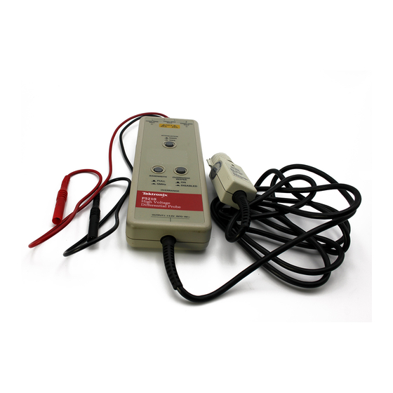
Features and Accessories The P5210 probe (Figure 1) provides a safe means of measuring circuits with floating high voltages. The probe outputs a low-voltage, ground-referenced signal for display on instruments with the... - Seite 7 Getting Started Figure 1: P5210 High-Voltage Differential Probe P5210 Instructions...
- Seite 8 WARNING. To avoid shock or burn hazard, use only the standard accessories or accessories that are rated for the application. Use the P5210 accessories with this product only. Keep your fingers behind the finger guard on the probe body whenever possible to reduce the risk of a shock from the circuit under test.
- Seite 9 If your oscilloscope does not support the TekProbe interface, you can use the optional 1103 probe power supply as an effective interface. Contact your local Tektronix representative for more information. Zero Adjust. Use the zero adjust to set the probe output to the zero reference point prior to making measure- ments.
- Seite 10 The hook tip is rated for the maximum input voltage of the P5210 probe. Install the small hook tip by sliding it over the body of the probe and screwing it onto the threaded probe tip To use the tip, hold the probe body and pull the tip shield back.
- Seite 11 The hook tip is rated for the maximum input voltage of the P5210 probe. Install the large hook tip by sliding it over the body of the probe and screwing it onto the threaded probe tip.
-
Seite 12: Installation
Getting Started Installation Install the P5210 probe as follows: 1. Connect the output of the probe to the TekProbe input of the oscilloscope or other measurement instrument. Make sure the measurement instrument is properly grounded. NOTE. Use the 1103 TekProbe Power supply if the instrument does not have the TekProbe interface. -
Seite 13: Functional Check
Getting Started Functional Check To make a simple functional check of the P5210 probe, select a source that supplies AC line voltage and use the following procedure. This procedure verifies a majority of the circuitry within the probe. (For a complete performance verification, refer to the service manual that accompanies this product.) -
Seite 14: Operating Basics
Operating Basics To help you use the P5210 High-Voltage Differential Probe safely and effectively, this section provides important information about safety limits, operating characteristics, and probing techniques. Operating the Probe Safely Before connecting the inputs of the probe to a circuit, read the safety information in this section and attach the appropriate accessories to the input connectors of the probe. - Seite 15 Operating Basics CAUTION. To avoid damaging the input circuitry of the P5210 probe, do not apply voltage that is more than 2,200 V between either input and earth ground or more than 4,400 V between the inputs. In addition, the peak voltage must be less than 5,600 V (DC + peak AC) between the inputs.
-
Seite 16: Operating Characteristics And Probing Techniques
Operating Limits The P5210 probe has two operating ranges that you select with the ATTENUATION button on the front panel: 1,000 X and 100X. These ranges set the maximum differential voltage that can be measured. -
Seite 17: Twisting The Input Leads
For a graph of frequency versus input impedance, refer to Figure 5 on page 22. As the graph shows, the probe has virtually no loading effect on sources with relatively low impedance and low frequency. P5210 Instructions... -
Seite 18: Cleaning
Remove dirt with a soft cloth dampened in a mild detergent and water solution or isopropyl alcohol. CAUTION. To avoid damaging the probe, use only a mild detergent and water solution or isopropyl alcohol, do not use any other solvents or abrasive cleaners. Do not immerse the probe. P5210 Instructions... -
Seite 19: Specifications
Specifications The specifications in Tables 2 through 6 apply to a P5210 probe installed on a Tektronix TDS 460A oscilloscope. When the probe is used with another oscilloscope, the oscilloscope must have an input impedance of 1 M and a bandwidth greater than 200 MHz. - Seite 20 Nonoperating: <85% RH at or below +60 C The rating for DC voltage is the same as the rating for RMS voltage. The input voltage must not exceed this peak rating or the RMS rating. Tektronix Design Standard 062-2847-00 P5210 Instructions...
- Seite 21 Equipment is usually cord-connected CAT I Secondary (signal level) or battery operated circuits of electronic equipment Pollution Degree 2 Do not operate in environments where conductive pollutants may be present. P5210 Instructions...
-
Seite 22: Typical Characteristics
8 M , 7 pF between each input and ground See Figure 5 Propagation Delay 20 nS Overdrive Recovery < 50 ns to 10% of final value after 10X overdrive (100X range only) DC Offset Adjust 100X: 1.0 V (referenced to input) 1,000X: 10 V P5210 Instructions... - Seite 23 Specifications 40 dB 50 dB 60 dB 70 dB 80 dB 90 dB 1 Hz 10 Hz 100 Hz 1 kHz 10 kHz 100 kHz 1 MHz Frequency Figure 4: Typical Common-Mode Rejection Ratio (100X Attenuation) P5210 Instructions...
- Seite 24 Unit Weight (probe only) 315 g (11 oz) Shipping Weight (with accessories) 1.42 kg (3 lb, 2 oz) 10 M 100 k 10 k 10 k 100 k 10 M 50 M Frequency (Hz) Figure 5: Input Impedance vs. Frequency P5210 Instructions...
-
Seite 25: Nominal Characteristics
Single-ended. Source Impedance of 50 drives 1 M oscilloscope input. Load impedance must be greater than 50 k for stated accuracy Gain Switchable: 1/100 (100X) and 1/1,000 (1000X) Overrange Beeper Overrange sounds whenever ON, and over range LED is lit. P5210 Instructions... - Seite 26 Tektronix, shipping charges prepaid, and with a copy of customer proof of purchase. Tektronix shall pay for the return of the product to Customer if the shipment is to a location within the country in which the Tektronix service center is located.
- Seite 29 Instructions Sonde différentielle haute tension P5210 070-9841-00...
- Seite 30 étrangères, publiées et en attente de publication. Les informations contenues dans le présent manuel remplacent et annulent toute documentation publiée antérieurement. Tektronix se réserve le droit de modifier les spécifications et indications de prix contenues dans le présent manuel. Imprimé aux Etats-Unis.
- Seite 31 ......Caractéristiques nominales ......Instructions pour la sonde P5210...
-
Seite 32: Consignes Générales De Sécurité
Maintenir la surface de la sonde propre et sèche. Pour éviter l’électrocu- tion ou les résultats erronés, maintenez la surface de la sonde propre et sèche. Instructions pour la sonde P5210... - Seite 33 Les termes définis ci-après peuvent figurer sur le produit : DANGER indique un risque immédiat de dommages matériels. AVERTISSEMENT indique un risque éventuel de blessures corporelles. ATTENTION indique un risque de dommages matériels, y compris pour la sonde. Instructions pour la sonde P5210...
- Seite 34 DANGER Borne de mise à la ATTENTION Double Haute terre Se reporter au isolation tension manuel Certifications et conformité Dans la section «Spécifications», vous trouverez une liste des certifications et conformités s’appliquant à ce produit. Instructions pour la sonde P5210...
-
Seite 35: Mise En Route
Fonctions et accessoires La sonde P5210 (figure 1) permet la mesure sans danger de circuits caractérisés par une haute tension flottante. La sonde génère en sortie un signal de faible tension, référencé à la masse, destiné à être affiché... - Seite 36 Mise en route Figure 1 : P5210 Sonde différentielle haute tension Instructions pour la sonde P5210...
- Seite 37 AVERTISSEMENT. Pour éviter tout risque de choc ou de brûlure, utilisez uniquement les accessoires dont les caractéristiques nominales conviennent à l’application. Les accessoires P5210 doivent être utilisés uniquement avec ce modèle de sonde. Dans la mesure du possible, maintenez les doigts derrière le protège-doigts situé...
- Seite 38 Tektronix. Réglage du zéro. Utilisez le réglage du zéro pour ajuster la sortie de la sonde au point de référence zéro avant de procéder aux mesures. Utilisez l’outil de réglage fourni. Instructions pour la sonde P5210...
- Seite 39 à de petits conducteurs, par exemple les fils de composants électriques. Cet embout est étudié pour la tension d’entrée maximum de la sonde P5210. Pour mettre en place l’embout à petit crochet, faites-le glisser sur le corps de la sonde et vissez-le sur l’embout fileté...
- Seite 40 à proximité de la tête de la sonde et la bande correspondante près du boîtier de compensation. La liste complète des accessoires remplaçables et des références de pièces à commander est à consulter dans le manuel de maintenance fourni avec ce produit. Instructions pour la sonde P5210...
-
Seite 41: Installation
Mise en route Installation Installez la sonde P5210 comme indiqué ci-après : 1. Connectez la sortie de la sonde sur l’entrée TekProbe de l’oscilloscope ou de l’appareil de mesure utilisé. Assurez-vous que l’appareil de mesure est relié à la terre. -
Seite 42: Vérification Fonctionnelle
1. Utilisez la procédure d’installation décrite à partir de la page 11 pour raccorder la sortie de la sonde P5210 à un appareil de mesure. 2. Reportez-vous au tableau 1 de la page 12. Branchez les entrées, réglez la plage et effectuez les vérifications indiquées sur les... -
Seite 43: Principes De Fonctionnement
Principes de fonctionnement Pour vous aider à utiliser la P5210 Sonde différentielle haute tension de façon efficace et sans danger, cette section contient des informations importantes relatives aux limites de sécurité, aux caractéristiques de fonctionnement et aux techniques d’utilisation de la sonde. -
Seite 44: Limites Supérieures De L'entrée
ATTENTION. Pour éviter d’endommager les circuits d’entrée de la sonde P5210, n’appliquez jamais de tension supérieure à 2 200V entre l’entrée et la terre ni de tension supérieure à 4 400 V entre les entrées. - Seite 45 RF (en grisé) fonction de la fréquence 4 000V 1 000V 500V Tension (efficace) 100V CC ou 0 100k 500k Fréquence (Hz) Figure 2 : Limites de sécurité (tension entre une entrée et la terre Instructions pour la sonde P5210...
-
Seite 46: Caractéristiques De Fonctionnement Et Techniques
Caractéristiques de fonctionnement et techniques d’utilisation de la sonde La présente section décrit les caractéristiques de fonctionnement de la P5210 Sonde différentielle haute tension ainsi que les techniques à utiliser pour tirer le meilleur parti des performances de la sonde. Limites de fonctionnement La sonde P5210 possède deux plages de fonctionnement sélection-... -
Seite 47: Réjection En Mode Commun
Réjection en mode commun Le taux de réjection en mode commun est la capacité définie de la sonde P5210 de rejeter des signaux communs aux deux entrées. Plus précisément, ce taux (CMRR) est le ratio du gain différentiel sur le gain en mode commun. -
Seite 48: Charge De La Sonde
ATTENTION. Pour éviter d’endommager la sonde, utilisez uniquement une solution de détergent et d’eau ou d’alcool isopropylique. N’utilisez ni solvant, ni tampon abrasif. La sonde ne doit jamais être immergée. Instructions pour la sonde P5210... -
Seite 49: Spécifications
La sonde doit avoir un temps de chauffe minimum de 20 minutes et être installée dans un environnement n’excédant pas les valeurs limite indiquées dans le tableau 2. Les spécifications de la sonde P5210 se répartissent en trois catégories : caractéristiques garanties, caractéristiques typiques et caractéristiques nominales. - Seite 50 La valeur nominale de la tension Vcc est identique à celle de la tension efficace. La tension d’entrée ne doit pas excéder cette valeur nominale, ni la valeur nominale efficace. Norme de conception Tektronix 062-2847-00 Instructions pour la sonde P5210...
- Seite 51 équivalents. Ces équipements sont généralement connectés au moyen d’un cordon. CAT I Equipements électroniques de niveau secondaire (niveau des signaux) ou alimentés par batterie. Degré de pollution 2 Ne pas utiliser dans des environnements contenant des polluants conducteurs. Instructions pour la sonde P5210...
-
Seite 52: Caractéristiques Typiques
Reprise de surmodulation < 50 ns jusqu’à 10% de la valeur finale après une surmodulation de 10X (plage 100X uniquement) Réglage décalage continu 100X : 1,0 V (référencé à l’entrée) 1 000X : 10 V Instructions pour la sonde P5210... - Seite 53 60 dB 70 dB 80 dB 90 dB 1 Hz 10 Hz 100 Hz 1 kHz 10 kHz 100 kHz 1 MHz Fréquence Figure 4 : Taux de réjection en mode commun typique (atténuation 100X) Instructions pour la sonde P5210...
- Seite 54 Poids emballé pour le transport 1,42 kg (avec accessoires) 10 M 100 k 10 k 10 k 100 k 10 M 50 M Fréquence (Hz) Figure 5 : Impédance d’entrée en fonction de la fréquence Instructions pour la sonde P5210...
-
Seite 55: Caractéristiques Nominales
à 50 kΩ pour la précision indiquée. Gain Sélectionnable : 1/100 (100X) et 1/1 000 (1 000X) Avertissement sonore du dépassement de Avertissement sonore du dépassement de plage plage lorsque cette fonction est activée et le voyant correspondant allumé. Instructions pour la sonde P5210... - Seite 56 GARANTIE Tektronix garantit le présent produit pendant une période d’un (1) an, à compter de la date d’achat auprès d’un distributeur Tektronix agréé, contre tout défaut de matériaux ou de main-d’oeuvre. Si un défaut vient à se manifester pendant cette période de garantie, Tektronix s’engage à...
- Seite 57 Anleitung P5210 Hochspannungs-Differentialtastkopf 070-9841-00...
- Seite 58 Copyright Tektronix, Inc. Alle Rechte vorbehalten. Tektronix-Produkte sind durch erteilte und angemeldete US- und Auslands- patente geschützt. Die Informationen der vorliegenden Veröffentlichung ersetzen alle früheren Angaben. Änderungen von Preisen und Spezifikationen vorbehalten. Printed in USA. Tektronix, Inc., P.O. Box 1000, Wilsonville, OR 97070–1000 USA TEKTRONIX, TEK und TEKPROBE sind eingetragene Warenzeichen von Tektronix, Inc.
- Seite 59 ......... P5210 Anleitung...
-
Seite 60: Zusammenfassende Sicherheitshinweise
Nicht in nasser oder feuchter Umgebung betreiben. Zum Schutz gegen Elektroschocks darf dieses Produkt nicht in nasser oder feuchter Umgebung betrieben werden. Nicht in explosionsgefährdeter Umgebung betreiben. Zum Schutz gegen Verletzungen oder Brandgefahr darf dieses Produkt nicht in explosionsgefährdeter Umgebung betrieben werden. P5210 Anleitung... -
Seite 61: Symbole Und Bezeichnungen Zur Sicherheit
In diesem Handbuch können die folgenden Bezeichnungen vorkommen: WARNUNG. weist auf Bedingungen oder Verfahrensweisen hin, die zu Verletzungen, auch mit Todesfolge, führen können. VORSICHT. weist auf Bedingungen oder Verfahrensweisen hin, die zu Schäden an diesem Produkt und zu sonstigen Sachschäden führen können. P5210 Anleitung... -
Seite 62: Zulassungen Und Übereinstimmungen
Das Produkt kann die folgenden Symbole tragen: GEFAHR Erdungsklemme ACHTUNG Doppelt Hoch (Masse) Siehe die Angaben Isoliert spannung im Handbuch Zulassungen und Übereinstimmungen Siehe eine Aufstellung der für dieses Produkt bestehenden Zertifizie- rungen und eingehaltenen Normen im Abschnitt „Spezifikationen.“ P5210 Anleitung... -
Seite 63: Zu Beginn
Oszilloskopen oder sonstigen Meß- geräten, wenn zusätzlich ein Netzteil 1103 TekProbe von Tektronix verwendet wird). Der Tastkopf P5210 erlaubt eine deutliche und genaue Messung von schnellen Spannungsspitzen bei ausgezeichneter Unterdrückung von Gleichtaktsignalen. Beide Eingänge besitzen eine hohe Impedanz mit geringer Kapazität. - Seite 64 Zu Beginn Abbildung 1: P5210 Hochspannungs-Differentialtastkopf P5210 Anleitung...
- Seite 65 Standardzubehör oder sonst für die betreffende Anwendung ausgelegtes Zubehör zu verwenden. Für dieses Produkt nur das zum P5210 gehörende Zubehör verwenden. Die Finger nach Möglichkeit immer hinter dem Fingerschutz auf der Prüfspitze halten, um jede Stromschlaggefahr aus der geprüften Schaltung auszuschließen.
- Seite 66 Tastkopf. Für Oszilloskope, die die Schnittstelle TekProbe nicht unterstützen, kann als Schnittstelle das als Option erhältliche Tastkopfnetzteil 1103 verwendet werden. Weitere Angaben hierzu sind vom örtlichen Tektronix- Vertragshändler zu erhalten. Nullpunktsabgleich. Mit dem Nullpunktsabgleich ist das Ausgangssignal des Tastkopfs vor Beginn der Messun- gen auf den Bezugsnullwert einzustellen.
- Seite 67 Die kleine Hakenspitze ist für Prüfungen an dünnen Adern vorgesehen, zum Beispiel an Bauelementeanschlüssen. Die Hakenspitze ist für die maximale Eingangsspannung des Tastkopfs P5210 ausgelegt. Die kleine Hakenspitze zur Installation auf das Ge- häuse der Prüfspitze aufschieben und auf dem Gewindebolzen festschrauben Zum Gebrauch das Gehäuse der Prüfspitze festhalten...
- Seite 68 Bauteilen gedacht, zum Beispiel an Schraubklemmen oder an Sammelschienen, wie sie für Stromversorgungseinrichtungen typisch sind. Die Hakenspitze ist für die maximale Eingangsspannung des Tastkopfs P5210 ausgelegt. Die große Hakenspitze zur Installation auf das Gehäuse der Prüfspitze aufschieben und auf dem Gewindebolzen festschrauben.
-
Seite 69: Installation
Zu Beginn Installation Der Tastkopf P5210 ist wie folgt zu installieren: 1. Den Ausgang des Tastkopfs mit dem Eingang TekProbe des Oszilloskops oder sonstigen Meßgeräts verbinden. Darauf achten, daß das Meßgerät gut geerdet ist. HINWEIS. Bei Geräten, die nicht die Schnittstelle TekProbe besitzen, ist das Netzteil 1103 TekProbe zu verwenden. -
Seite 70: Funktionskontrolle
Leistungsdaten siehe das Wartungshandbuch, das zu diesem Produkt mitgeliefert wird.) 1. Den Ausgang des Tastkopfs P5210 gemäß der Beschreibung der Installation, Seite 11, an ein Meßgerät anschließen. 2. Siehe die Tabelle 1 auf Seite 12. Gemäß den Angaben in den Zeilen der Tabelle 1 jeweils die Eingänge anschließen, Bereiche... -
Seite 71: Betriebsgrundlagen
Betriebsgrundlagen Der hier folgende Abschnitt enthält wichtige Angaben zu Sicher- heitsgrenzwerten, Betriebskenndaten und Arbeitstechniken, die dazu beitragen sollen, den P5210 Hochspannungs-Differentialtastkopf gefahrlos und effektiv zu nutzen. Sicherer Betrieb des Tastkopfs Die Sicherheitsangaben dieses Abschnitts beachten und das ent- sprechende Zubehör an den Eingangsanschlüssen des Tastkopfs befestigen, bevor die Prüfspitzen mit einer Schaltung verbunden... -
Seite 72: Maximale Eingangsspannungen
Effektivwerte (EFF).) Es sind auch die Grenzwerte der Spannungen zwischen den Differenzeingängen sowie von diesen gegen Masse einzuhalten. VORSICHT. Zum Schutz der Eingangsschaltungen des Tastkopfs P5210 dürfen keine Spannungen angelegt werden, die höher als 2.200V gegen Masse oder höher als 4.400 V zwischen den Eingängen sind. - Seite 73 Gefahr von Absenkung der Höchstspannungen der HF-Verbrennungen Spannung bei höheren Kategorie II (2.200 V) (schraffiert) Frequenzen 4000V 1000V 500V Spannung (effektiv) 100V DC / 0 100k 500k Frequenz (Hz) Abbildung 2: Sicherheitsgrenzwerte (Spannung an jedem der Eingänge gegen Masse P5210 Anleitung...
-
Seite 74: Betriebskenndaten Und Arbeitstechniken
Leistungsfähigkeit des Tastkopfs maximal nutzen läßt. Einsatzgrenzen Der Tastkopf P5210 verfügt über zwei Einsatzbereiche, die mit der Taste ATTENUATION in der Frontplatte einzustellen sind: 1000 X und 100X. Diese Bereiche geben die Differenzspannungen vor, die maximal gemessen werden können. -
Seite 75: Gleichtaktunterdrückung
Gleichtaktunterdrückung Das Verhältnis der Gleichtaktunterdrückung (Common-mode rejection ratio, CMRR) gibt die spezifische Fähigkeit des Tastkopfs P5210 an, Signale zu unterdrücken, die gleichzeitig an beiden Eingängen anliegen. Das CMRR bezeichnet, noch genauer, das Verhältnis des differentiellen Verstärkungsfaktors zum Gleichtakt- Verstärkungsfaktor. Je größer dieses Verhältnis ist, desto besser unterdrückt der Tastkopf Gleichtaktsignale. -
Seite 76: Belastung Durch Den Tastkopf
Verschmutzungen sind mit einem weichen Tuch abzuwischen, das mit einer schwachen wässrigen Reinigungslösung oder mit Isopropylalkohol befeuchtet wurde. VORSICHT. Zum Schutz gegen Beschädigungen des Tastkopfs nur eine schwache wässrige Reinigungslösung oder Isopropylalkohol verwenden, keinesfalls sonstige Lösemittel oder gar Scheuermittel. Den Tastkopf nicht untertauchen. P5210 Anleitung... -
Seite 77: Spezifikationen
Der Tastkopf muß sich mindestens 20 Minuten lang auf Betriebstem- peratur erwärmt haben und unter Bedingungen betrieben werden, die die in Tabelle 2 beschriebenen Grenzwerte einhalten. Die Spezifikationen für den Tastkopf P5210 gliedern sich in drei Kategorien: garantierte Kenndaten, typische Kenndaten und Nenndaten. - Seite 78 Betriebsbereich: <85% rF bis max. +35 C Lagerbereich: <85% rF bis max. +60 C Gleichspannungen (DC) sind bis zur Höhe des entsprechenden Effektiv- werts (EFF) zulässig. Die Eingangsspannung darf diesen Spitzenwert oder den Effektivwert nicht übersteigen. Konstruktionsstandard Tektronix 062-2847-00 P5210 Anleitung...
- Seite 79 Stufe sind Haushaltsgeräte, Handwerkzeuge und ähnliche Produkte. Die Einrichtungen sind meist über ein Netzkabel angeschlossen CAT I Mit Kleinspannungen (Signalebene) oder aus Batterien betriebene Schaltungen von elektronischen Geräten Schadstoffe Stufe 2 Nicht unter Umgebungsbedingungen betreiben, bei denen leitfähige Stäube vorliegen können. P5210 Anleitung...
-
Seite 80: Typische Kenndaten
Masse (Siehe Abbildung 5) Signallaufzeit 20 ns Erholung nach Übersteuerung < 50 ns bis auf 10% des Endwerts nach Übersteuerung 10X (nur im Bereich 100X) Einstellung des DC-Offsets 100X: + 1,0 V (bezogen auf den Eingang) 1,000X: + 10 V P5210 Anleitung... - Seite 81 Spezifikationen 40 dB 50 dB 60 dB 70 dB 80 dB 90 dB 1 Hz 10 Hz 100 Hz 1 kHz 10 kHz 100 kHz 1 MHz Frequenz Abbildung 4: Typisches Verhältnis der Gleichtaktunterdrückung (im Bereich 100X) P5210 Anleitung...
- Seite 82 45,7 cm Abmessungen, Ausgangskabel 1,8 m Stückgewicht (nur Tastkopf) 315 g Versandgewicht (mit Zubehör) 1,42 kg 10 M 100 k 10 k 10 k 100 k 10 M 50 M Frequenz (Hz) Abbildung 5: Eingangsimpedanz über der Frequenz P5210 Anleitung...
-
Seite 83: Nenndaten
1 M . Der angegebene Amplitudengang wird nur bei Lastimpedanzen von über 50 k erreicht. Verstärkungsfaktor Umschaltbar: 1/100 (100X) und 1/1000 (1000X) Tonzeichen für Bereichsüberschreitung Das Tonzeichen für Bereichsüberschreitung ertönt nach Freigabe (Taste ON), wenn die LED zur Anzeige der Bereichsüberschrei- tung aufleuchtet. P5210 Anleitung... - Seite 84 Tektronix angegebene Service Center zu senden, wo- bei ein Nachweis über den getätigten Kauf beizufügen ist. Tektronix trägt die Kosten für die Rücksendung des Produkts an den Kunden, wenn der Bestimmungsort in dem Land liegt, in dem sich das Tektronix Service Center befindet.